EP1775103A2 - Systèmes et procédés pour la fabrication des formes libres solides avec des bacs de poudre mobiles en translation - Google Patents
Systèmes et procédés pour la fabrication des formes libres solides avec des bacs de poudre mobiles en translation Download PDFInfo
- Publication number
- EP1775103A2 EP1775103A2 EP06019288A EP06019288A EP1775103A2 EP 1775103 A2 EP1775103 A2 EP 1775103A2 EP 06019288 A EP06019288 A EP 06019288A EP 06019288 A EP06019288 A EP 06019288A EP 1775103 A2 EP1775103 A2 EP 1775103A2
- Authority
- EP
- European Patent Office
- Prior art keywords
- bin
- build
- powder
- print head
- powder supply
- Prior art date
- Legal status (The legal status is an assumption and is not a legal conclusion. Google has not performed a legal analysis and makes no representation as to the accuracy of the status listed.)
- Withdrawn
Links
Images



Classifications
-
- B—PERFORMING OPERATIONS; TRANSPORTING
- B29—WORKING OF PLASTICS; WORKING OF SUBSTANCES IN A PLASTIC STATE IN GENERAL
- B29C—SHAPING OR JOINING OF PLASTICS; SHAPING OF MATERIAL IN A PLASTIC STATE, NOT OTHERWISE PROVIDED FOR; AFTER-TREATMENT OF THE SHAPED PRODUCTS, e.g. REPAIRING
- B29C64/00—Additive manufacturing, i.e. manufacturing of three-dimensional [3D] objects by additive deposition, additive agglomeration or additive layering, e.g. by 3D printing, stereolithography or selective laser sintering
- B29C64/10—Processes of additive manufacturing
- B29C64/165—Processes of additive manufacturing using a combination of solid and fluid materials, e.g. a powder selectively bound by a liquid binder, catalyst, inhibitor or energy absorber
-
- B—PERFORMING OPERATIONS; TRANSPORTING
- B33—ADDITIVE MANUFACTURING TECHNOLOGY
- B33Y—ADDITIVE MANUFACTURING, i.e. MANUFACTURING OF THREE-DIMENSIONAL [3D] OBJECTS BY ADDITIVE DEPOSITION, ADDITIVE AGGLOMERATION OR ADDITIVE LAYERING, e.g. BY 3D PRINTING, STEREOLITHOGRAPHY OR SELECTIVE LASER SINTERING
- B33Y30/00—Apparatus for additive manufacturing; Details thereof or accessories therefor
-
- B—PERFORMING OPERATIONS; TRANSPORTING
- B33—ADDITIVE MANUFACTURING TECHNOLOGY
- B33Y—ADDITIVE MANUFACTURING, i.e. MANUFACTURING OF THREE-DIMENSIONAL [3D] OBJECTS BY ADDITIVE DEPOSITION, ADDITIVE AGGLOMERATION OR ADDITIVE LAYERING, e.g. BY 3D PRINTING, STEREOLITHOGRAPHY OR SELECTIVE LASER SINTERING
- B33Y50/00—Data acquisition or data processing for additive manufacturing
- B33Y50/02—Data acquisition or data processing for additive manufacturing for controlling or regulating additive manufacturing processes
Definitions
- Conventional powder supply and build bins in solid freeform fabrication (SFF) systems include vertical walls attached to the working surface of the SFF machine and a permanent bottom plate that is height-controlled throughout the build process.
- the bottom plate of the powder-source bin increments upward during the build process to provide additional powder that can be spread above a build plate in the build bin.
- the build plate is simultaneously incremented downward to accept a new layer of build powder. Regardless of the size of the desired prototype, or build, a volume of powder to fill the entire build bin to the height of the parts being built is required. This can sometimes limit the ability of a user to produce parts with limited powder on-hand.
- SFF systems have powder bins that are stationary in the x- and y-axes (when viewing the system from above).
- the printing mechanism moves in both the x- and y-axes in order to deposit a binder and/or ink in the desired location on the build plate.
- SFF systems In order to translate the printing mechanism, SFF systems have large servo and translation mechanisms, which can by heavy and take up more space than desired.
- SFF systems have utilized printing mechanisms that are specially manufactured for such systems, rather than the types of printing mechanisms that are manufactured in high volume for convention inkjet printers.
- the disclosed solid freeform fabrication (SFF) systems have incorporated therein a convenient supply powder and build bin packaging.
- the supply powder bin and/or build bin can include a removable top, four side walls, a piston-like bottom that supports the powder and allows a printer piston to feed powder to the spreader during the printing and object fabrication process, and features that easily locate/attach/register the bin with the SFF system.
- the disclosed bins can be either disposable or reusable and are configured to be interchangeable within the SFF system. The disclosed bins simplify the set-up process, as well as reduce the powder spillage and the required clean up associated with three-dimensional (3D) printing and selective laser sintering (SLS) processes.
- 3D three-dimensional
- SLS selective laser sintering
- FIG. 1 illustrates one solid freeform fabrication system that uses 3D printing technology.
- the disclosed powder bins, apparatuses, and methods can also be applied to SLS systems.
- a powdery material e.g., a plaster- or starch-based powder
- a measured quantity of powder is first provided from a removable supply chamber or bin in the solid freeform fabrication system 100.
- a powder spreading mechanism such as a roller, preferably incorporated into a movable stage 103, then distributes and compresses the powder at the top of a fabrication chamber or removable build bin 102 to a desired thickness.
- a print head (not shown) deposits an adhesive or binder onto the powder in the build bin 102 in a two dimensional pattern. This two dimensional pattern becomes a thin cross section of the desired product.
- the print head may also eject colored binder, toner, and/or color activator into the layer of powder to provide a desired color or color pattern for this particular cross section of the desired product.
- a print head is described with respect to FIG. 1 as an example, other binding apparatuses can be used, for example, a laser that sinters the powder.
- the build bin 102 (in which the object sits) is repositioned downward along the z-axis so that the next layer of the object can be formed on top of the previously formed layer.
- the build bin 102 can have dimensions such as 8"x10"x10" or 6"x6"x6" to accommodate fabricators and 3D objects of various sizes.
- a user interface or control panel 105 can be provided to allow the user to control the fabrication process.
- the build bin 102 can be removed from the SFF system 100 so that the fabricated object can be removed from the build bin 102 outside of the SFF system 100.
- the extra powder that is not bonded by the adhesive is then brushed or vacuumed away leaving the base or "green" object.
- the SFF system 100 also includes a controller (not shown) which is programmed to, among other things, control the positioning and repositioning of the print head 103 during the 3D object fabrication process.
- the controller can take the form of a discrete module positioned proximate to the print head; alternatively, the operations performed by the controller can be distributed among a plurality of controllers, processors or the like, and/or the controller can be remotely located relative to the print head.
- Such a printing process offers the advantages of speedy fabrication and low materials cost. It is considered one of the fastest solid freeform fabrication methods, and can be performed using a variety of colors.
- the print head in the SFF system 100 can include inkjet technology for ejecting a binder or adhesive on a powder layer to form the layers of the desired object.
- inkjet technology the print head ejects drops of binder in a selective pattern to create the image being printed, or in the case of solid freeform fabrication, to color the object being fabricated.
- binder is used broadly to mean any substance ejected by a print head to form an object being fabricated. Consequently, the term “binder” includes, but is not limited to, binders, adhesives, etc.
- the binder can be, for example, clear (to create non-colored parts) or colored (to create colored objects or parts of objects).
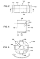
- FIG. 2 illustrates a partial top view of the SFF system 100 of FIG. 1, showing an exemplary supply bin 110 and a build bin 102 adjacent the supply bin 110.
- the roller 112 traverses the supply bin 110, and moves a very thin layer of powder from the top surface of the supply bin 110 onto a platform of the build bin 102. Thereafter, the print head 103 deposits the binder onto the powder layer on the platform of the build bin 102, thereby forming one layer of the desired object.
- a shallow catch bin 104 Shown in the embodiment of FIG. 2, on the opposite side of the build bin 102 from the supply bin 110 is a shallow catch bin 104.
- the shallow catch bin 104 can catch small amounts of excess powder that is a natural part of the spreading process. This can allow for easier segregation of different powder types.
- the catch bin 104 can be of a different size and in a different location than that shown in FIG. 2, based on how powder is provided to the catch bin 104, and where handles are located on the catch bins for removing them.
- the excess powder can be captured in a larger default catch bin (not shown) disposed on the side of the build bin 102 opposite the powder supply bin 110.
- the supply bin 110, the build bin 102, and/or the catch bin(s) 104 are designed to be easily removable from the system 100.
- the supply bin 110 and/or the build bin 102 can thus be reused for another fabrication or disposed of.
- FIG. 3 illustrates a partial cross section of an embodiment of the disclosed SFF system 100, taken along section line A-A in FIG. 2.
- FIG. 3 shows the exemplary build bin 102 (a) during fabrication of an object 101, and (b) after fabrication of the object 101, while the object 101 is seated in a bed of powder 128 in the build bin 102.
- the embodiment of the build bin 102 depicted in FIG. 3 includes a removable lid 114, rigid boundaries or side walls 116 (e.g., four side walls for a square or rectangular bin), and a bottom moveable platform 118 that can be operated in the z-direction by a linear motion actuator 119 already in place in the solid freeform fabrication system 100.
- the build bin 102 can also have a quick-release interface 121 that interacts with a linear motion actuator 119 such that the actuator 119 can engage the bottom moveable platform 118.
- the quick-release interface 121 can be, for example, a latch, a magnet, or other device(s) that would allow the actuator 119 to easily engage and then release the platform 118.
- the build bin 102 may not include the quick-release interface 121.
- the actuator 119 is depicted in FIG. 3 as a piston cylinder, it could instead be, for example, linear motors, lead screws, servo motors, hydraulic pistons, air-driven pistons, etc.
- the build bin housing 126 can have, for example, grooves that can accommodate matching protrusions on the build bin 102 (not shown), or simple mechanical latches.
- the build bin 102 (or supply bin 110) can have one or more mechanical interfaces between the bin and the SFF system 100 that locate the bin in the desired location (x-, y-, and z-planes).
- the interfaces can be, for example, one or more flanges, a slidable mechanism (in y- or z-direction), or one or more dowels that protrude from a side of the bin housing.
- the bin(s) drop into the system in the z-direction, and have interfaces that hold and locate it approximately flush with the working surface of the system 100.
- the bins have a pair of upper flanges 122 that extend beyond the side walls of the bin in the y-direction, and engage at least one upper working surface 124 in the system 100.
- the upper flanges 122 engage an upper surface 124 of the bin housing 126 and aid in placement of the build bin 102 and/or maintaining the build bin 102 in place during operation of the system 100.
- one embodiment of the build bin 102 can have mechanical latches or magnets to ensure that only the powder is lifted by the actuator 119, and not the entire bin 102 itself. Positive downward force can be applied by cam action or springs in the latches.
- the build bin 102 can include vertical registration components such vertical pins with hardened points on the tips, located in the system 100, that contact either the bottom surface 118 or the flanges 122 or lip around the bin 102. Use of registration components minimizes the possibility of powder interfering with the registration interface.
- the bin 102 can include one or more seating sensors (not shown) to detect when the bin 102 is properly seated in the system 100. Seating sensor(s) can be, for example, an electrical continuity check, a Hall effect sensor, a through-beam or reflected light sensor, and/or a high precision switch.
- the seating sensor can also include mechanical or electrical lockout features to ensure use of materials that are compatible with the SFF system.
- the linear motion actuator 119 pulls downward on the bottom moveable platform 118, which fits exactly inside the side walls 116 of the build powder bin 102.
- the build bin 102 includes a pair of lower flanges 120 that extend beneath and parallel to the bottom moveable platform 118, on which the platform 118 rests when the build bin 102 is full of powder and the fabricated part(s), as shown in FIG. 3 (b).
- the lid 114 is removed, thereby exposing the next layer of powder 128 for fabrication.
- the actuator 119 acts on the platform 118 to pull the platform 118 downward in the z-direction.
- a thin layer of powder 128 is deposited, the excess of which can be rolled forward in the y-direction toward a catch bin (not shown) by the roller 112, exposing one thin layer of powder 128 for each layer of the device or object fabrication.
- the removable lid 114 can be, for example, a lid that peels back, or even completely off, slides on or off, or that snaps onto and off of a lip (not shown) of an upper surface of the build bin 102.
- the lid can also be designed, as in a snap-fit lid, to be re-installed after fabrication of an object so that the build bin 102, when full of powder and the fabricated object, can be removed from the system 100 with minimal risk of spilling the powder and/or creating airborne powder migration.
- the lid can be opened and/or removed either manually or by components in the SFF system 100.
- the embodiment of the build bin 102 depicted in FIG. 3 includes a removable lid 114, in some embodiments the build bin 102 may not include the lid 114.
- the material of the build bin 102 can be any material that is sufficiently rigid to support a bin full of powder or slurry.
- the material can be a metal or metal alloy, cellulosic material, or hard, stiff plastic (e.g. , thermosets and thermoplastics, including for example, acetals, acrylics, terpolymers, alkyds, melamines, phenolic resins, polyarylates, polycarbonates, high density polyethylene, polyphenylene sulfide, polystyrene, polyvinyl chloride, styrene acrylonitrile, polyphenylsulfone, sulfones, unsaturated polyesters, polypropylene, polytetrafluoroethylene, polyethersulfone, polyetherketone, liquid crystalline polymers, or urea-formaldehyde molding compounds, etc .).
- thermosets and thermoplastics including for example, acetals, acrylics, terpolymers, alky
- the material of the build bin 102 can also include fillers for the polymers, the fillers being designed to be compatible with each polymer.
- the fillers can impart various properties to the polymeric material, such as increased strength.
- the build bin 102 can be designed to be either disposable or reusable, depending on the material selected for the build bin 102.
- the build bin 102 includes low friction surfaces on side walls 116, whereby powder contained in the build bin 102 slides easily along the bin walls throughout the fabrication process.
- FIG. 4 illustrates a cross sectional view of an embodiment of the build bin 105 taken along section line A-A in FIG. 2, the build bin 105 being a bag-like material.
- FIG. 4 shows the exemplary build bin 105 (a) during fabrication of the object 101, and (b) after fabrication of the object 101, while the object 101 is seated in a bed of powder 128 in the build bin 105.
- the build bin 105 includes a removable lid 114, a bag compartment 132, and a pair of upper flanges 122 that extend from an upper surface of the bin 105.
- the bag compartment 132 depicted in FIG. 4 includes a crinkle zone 133 that enables the bag to fold easily as a platform 140 and the actuator 119 operate on the bag compartment 132 in the z-direction.
- the space/clearance between the bag compartment 132 and side walls in a build bin housing 144 is large enough to accommodate collapsed folds of the bag compartment 132.
- the bag compartment 132 depicted in FIG. 4 includes a crinkle zone 133, other embodiments may not include the crinkle zone 133.
- the platform 140 and actuator 119 can be already in place in the system 100, and the build bin 105 is inserted to rest on top of the platform 140.
- the actuator 119 in one embodiment can have struts 142 to stabilize the actuator 119 during movement.
- the struts 142 can be, for example, a stiff metal, metal alloy, or a hard plastic material. In other embodiments, the actuator 119 may not have struts 142.
- the build bin 105 can have a pair of upper flanges 122 that extend beyond the side walls.
- the upper flanges 122 engage an upper surface 124 of the bin housing 126 and aid in placement of the build bin 105.
- the upper flanges 122 are of a stiffer material than the bag compartment 132 in order to aid in proper placement of the bag compartment 132.
- the upper flanges can be made of, for example, a cellulose-based material (e.g., cardboard), a metal, or a hard plastic.
- the linear motion actuator 119 pulls downward on the platform 140, which fits exactly inside the side walls of the build bin housing 144 in the system 100.
- the lid 114 is removed, thereby depositing the powder.
- the actuator 119 acts on the platform 140 to pull the platform 140 downward, in the z-direction.
- the bag compartment 132 unfolds and is pulled downward by gravity.
- a thin layer of powder 128 is exposed, the excess of which can be rolled forward in the y-direction toward a catch bin (not shown) by the roller 112 (see FIG. 2), exposing one thin layer of powder 128 for each layer of the device fabrication.
- the removable lid 114 can be, for example, a lid that peels back or even completely off, or that snaps onto and off of a lip (not shown) of an upper surface of the build bin 105.
- the material of the bag compartment 132 can be any material that is sufficiently rigid to support a bin full of powder or slurry, yet sufficiently pliable to unfold upon expansion caused by the lowering of the actuator 119 and platform 140.
- the bag compartment is chosen to provide a barrier to environmental conditions such as, for example, air, humidity, moisture, grease, and/or light, etc.
- the material of the bag compartment 132 can be any flexible polymeric material.
- the build bin 105 can be designed to be either disposable or reusable, depending on the material selected for the build bin 105. By using a bag compartment 132 for the build bin 105, the tolerance between the platform 140 and the side walls of the bin housing 144 can be reduced, as well as eliminating the need for o-rings that are typically used to create a tight seal.
- the supply bin 110 and the build bin are configured to be interchangeable.
- the supply and build bins can both be removable, and be of the same size and shape to allow each one to fit into a housing for the other one.
- the build bin 102 can include a memory mechanism 146 that can communicate information to the controller about the supply bin, such as, for example, powder volume, powder type, bin manufacturer (e.g., to help determine if the supply bin is a genuine supply bin), allowable binder types for the powder, recommended spread-roller rotation speed, supply bin z-step size, expiration date of the powder, drop volume needed for a given layer thickness, setting time, etc.
- the memory mechanism 146 can be, for example, an integrated circuit (IC) chip, a tag or label with a bar code, and/or a mechanical device that conveys information about the powder level and/or the bin.
- IC integrated circuit
- An example of a mechanical device used as the memory mechanism 146 includes "break tabs," where certain tabs indicate a particular bin size and/or powder type.
- the SFF system 100 can be configured to determine which tabs are present upon insertion via sensors, switches, or other means.
- information about powder volume can be conveyed where the memory mechanism 146 includes a "gas gauge” type of device that tracks and conveys information about the remaining volume of powder after some usage.
- the solid freeform fabrication system 100 can include a sensor that is capable of reading the memory mechanism 146.
- the system 100 can use information from the build bin in tandem with the information from the inkjet supply's memory chip to ensure, for example, that the correct binder liquid and powder are mixed.
- the system 100 can also use the data encoded in or on the memory mechanism 146 to determine certain operating parameters, such as for example, print speed, drop volume per voxel, color maps, dry time needed after build completion, shrink or expansion size, adjustment factors, powder settling coefficients (e.g., to determine whether powder supports need to be included, and if so, how much support), minimum allowable layer thickness, etc.
- Communication with the IC can be via contact pads or wireless via radio frequency signals.
- the bar codes are read only, whereas the IC can be written to.
- the memory mechanism 146 can be placed anywhere on the build bin, so long as a sensor in or on the SFF system 100 can read it.
- the build bin 102 can include a handle 148.
- the handle 148 can be in any configuration (e.g., square or semicircular) and can be removable, collapsible, telescoping, and/or magnetic.
- the handle can be a notch or set of notches, inset into the build bin 102 or 105.
- the build bin is designed so that it can be removed from the system 100 by grasping and pulling on the handle 148, or inserting a removable handle into the features provided.
- Fig. 6 illustrates a top view of an embodiment of a continuous printing platform 200 that can be used in the system 100 of Fig. 1.
- Multiple removable bins 250 are disposed in the substantially circular printing platform 200.
- the bins 250 are interchangeable powder supply bins or build bins.
- Disposed over the bins 250 is a print bar/powder spreader 260.
- the print head can be disposed on the same print bar/powder spreader 260 as the powder spreader, as shown in Fig. 6, or can be disposed on a separate mechanism (not shown).
- the printing platform includes an extra powder chute 270. Other embodiments may not include the powder chute 270.
- the chute 270 in one embodiment is disposed between two of the removable bins 250.
- the printing platform 200 rotates in a clockwise direction in one embodiment. In another embodiment, the printing platform rotates in a counter-clockwise direction. In this manner, the printbar/powder spreader 260 spreads the powder from a first bin 250 onto a build platform of a second bin 250. The printbar/ powder spreader 260 then ejects binder onto the powder on the layer of powder platform, thus fabricating at least one layer of an object.
- the configuration of the printing platform 200 depicted in Fig. 6 allows multiple build bins to be printed at once, and also allows a continuous process.
- the printing platform 200 depicted in Fig. 6 increases the utilization of the print head during the printing process and increases utilization of the SFF system 100 by not necessitating that every part within the multiple bins 250 be completed at one time.
- the printing platform 200 is fixed and the printbar/powder spreader 260 rotates over the bins.
- the bins include features that allow attachment to other pieces of the system 100 for further processing.
- the bins can include features for attachment to other equipment such as, for example, a dryer, a de-powdering station, a powder refill station, a powder packaging station (for either reusable powder or for packing fresh containers after shipping), etc.
- SFF systems that include translating powder bins.
- the powder supply bin and/or the build bin can move along x- and/or y-axes relative to the print head.
- the target surfaces of the powder supply bin 110 and the build bin 102 of the SFF system 100 are located in close, working proximity to (e.g., at a predetermined initial distance from) the print head 103.
- the target surface of the build bin 102 can have a flat region sufficiently large to accommodate the layers of powder from the supply bin 110 that are deposited thereon by the roller 112.
- the print head 103 and one or both of the supply bin 110 and the build bin 102 are equipped with mechanical drive mechanisms.
- the mechanical drive mechanisms can translate the bin(s) relative to the movable dispensing head in three dimensions along x- an y-axes in a predetermined sequence and pattern, and/or displace the print head 103 a predetermined incremental distance relative to the bin(s). This can be accomplished, for instance, by allowing the bin(s) and the print head 103 to be driven by one, two, or three separate linear motion devices, which are powered by, for example, one, two, or three separate servo motors. Linear motion devices and x-, y-, z-gantry tables are commercially available.
- the powder bin platforms move in the z-axis direction.
- the entire bin(s) can move in the z-axis, for example, to provide additional clearance for roller translation or powder to pen spacing if needed for a particular step, such as UV curing.
- the pens of the print head can move in the z-axis.
- the pens can translate in the z-direction to allow for servicing a part or parts of the system 100.
- z-axis movements can also be effected to displace a nozzle of the print head 103 relative to the build bin 102 and, hence, relative to each layer deposited prior to the start of the formation of each successive layer. This will make it possible to form multiple layers of predetermined thicknesses, which build up on each other sequentially as the material composition solidifies after being discharged from an orifice in the nozzle.
- X- and y-axis movements are effected to fabricate a device of a desired size and shape.
- servo motors many other types of driving mechanism can be used, including for example, linear motors, stepper motors, synchronous motors, D.C. motors, and fluid motors. It will be understood that movement in the x-y plane need not be limited to movement in orthogonal directions, but may include movement in radial, tangential, arcuate, and other directions in the x-y plane.
- By allowing one or more bins to move relative to the print head smaller driving and translation mechanisms can by used, which in turn can reduce the overall size, weight, and cost of a SFF system.
- print heads employed in conventional inkjet printers that are manufactured in high volumes can be used in embodiments of the disclosed SFF in which one or both of the bins can translate relative to the print heads.
- both the powder supply bin 110 and the build bin 102 are attached to a single stage and translate relative to the print heads 103 in the y-axis.
- the print head 103 translates in the x-axis by, for example, a belt drive mechanism.
- the roller 112 is can spin, with its longitudinal axis remaining fixed in place.
- the roller axis can be moved relative to, and/or independent the translation of, the powder bins.
- moving the roller at least partway and the bins partway can save on the overall space used for bin translation.
- the powder supply bin 110 and the build bin 102 are on separate stages.
- the supply bin 110 is stationary, with the build bin 102 translating in the x- and/or y-axis.
- the roller 112 also, translates in the y-axis.
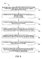
- FIG. 9 is a flow diagram describing a representative method 300 for forming a three-dimensional object, using the solid freeform fabrication system 100.
- block 310 removable, disposable, and/or reusable powder supply and build bins are inserted into a solid freeform fabrication system.
- block 320 an interconnect is formed between the powder supply bin and a piston cylinder in the solid freeform fabrication system.
- gravity alone is sufficient to provide an interconnection between the bin(s) and the piston and the powder supply bin does not include an interconnect and the step depicted in block 320 is not performed.
- an interconnect is formed between the build bin and a piston in the SFF system 100.
- an interconnect is also formed between the build bin or both the supply bin and the build bin to a stage that translates in x- and/or y-axis relative to a printing mechanism in the SFF system.
- gravity alone is sufficient to provide an interconnection between the bin(s) and the piston and the build bin and/or stage does not include an interconnect and the step depicted in block 330 is not performed.
- information can be communicated from the powder supply bin to a controller for the solid freeform fabrication system. Powder is then dispensed from the powder bin onto a build platform, as shown in block 360. In some embodiments of the method 300, information may not be communicated from the powder supply bin to the controller, and the step depicted in block 360 is not performed.
- Block 370 shows how an object is built in a build bin, by ejecting a binder from, for example, an inkjet print head, onto the layer of powder on the build platform, thereby forming layers of the object.
- a binder from, for example, an inkjet print head
- the steps of the disclosed methods can be performed out of order from the sequence(s) discussed herein.
- the steps depicted in blocks 320 and 330 can be performed in reverse order and/or simultaneously.
Landscapes
- Chemical & Material Sciences (AREA)
- Engineering & Computer Science (AREA)
- Materials Engineering (AREA)
- Manufacturing & Machinery (AREA)
- Physics & Mathematics (AREA)
- Mechanical Engineering (AREA)
- Optics & Photonics (AREA)
Applications Claiming Priority (1)
| Application Number | Priority Date | Filing Date | Title |
|---|---|---|---|
| US11/251,159 US7296990B2 (en) | 2005-10-14 | 2005-10-14 | Systems and methods of solid freeform fabrication with translating powder bins |
Publications (1)
| Publication Number | Publication Date |
|---|---|
| EP1775103A2 true EP1775103A2 (fr) | 2007-04-18 |
Family
ID=37684796
Family Applications (1)
| Application Number | Title | Priority Date | Filing Date |
|---|---|---|---|
| EP06019288A Withdrawn EP1775103A2 (fr) | 2005-10-14 | 2006-09-14 | Systèmes et procédés pour la fabrication des formes libres solides avec des bacs de poudre mobiles en translation |
Country Status (2)
| Country | Link |
|---|---|
| US (1) | US7296990B2 (fr) |
| EP (1) | EP1775103A2 (fr) |
Cited By (5)
| Publication number | Priority date | Publication date | Assignee | Title |
|---|---|---|---|---|
| WO2015081926A1 (fr) * | 2013-12-02 | 2015-06-11 | Voxeljet Ag | Caisse mobile pourvue d'une paroi latérale mobile |
| US9174392B2 (en) | 2009-06-22 | 2015-11-03 | Voxeljet Ag | Method and device for switching a particulate material flow in the construction of models in layers |
| WO2017034951A1 (fr) | 2015-08-21 | 2017-03-02 | Aprecia Pharmaceuticals Company | Système d'impression tridimensionnelle et ensemble d'équipement |
| EP3165304A1 (fr) * | 2015-11-04 | 2017-05-10 | Ricoh Company, Ltd. | Appareil de fabrication d'objet tridimensionnel |
| WO2019231441A1 (fr) * | 2018-05-30 | 2019-12-05 | Hewlett-Packard Development Company, L.P. | Bac de construction de fabrication additive |
Families Citing this family (80)
| Publication number | Priority date | Publication date | Assignee | Title |
|---|---|---|---|---|
| GB0317387D0 (en) * | 2003-07-25 | 2003-08-27 | Univ Loughborough | Method and apparatus for combining particulate material |
| US7722735B2 (en) * | 2006-04-06 | 2010-05-25 | C3 Materials Corp. | Microstructure applique and method for making same |
| WO2008151063A2 (fr) * | 2007-05-31 | 2008-12-11 | Milton Meisner | Procédé et matériau stéréolithique polyvalent haute définition |
| US10226919B2 (en) | 2007-07-18 | 2019-03-12 | Voxeljet Ag | Articles and structures prepared by three-dimensional printing method |
| DE102007050953A1 (de) | 2007-10-23 | 2009-04-30 | Voxeljet Technology Gmbh | Vorrichtung zum schichtweisen Aufbau von Modellen |
| EP2508325A3 (fr) * | 2008-04-10 | 2013-05-22 | Objet Ltd. | Système et procédé pour l' impression de modèles en trois dimensions |
| CN102164734B (zh) * | 2008-07-25 | 2014-06-11 | 康奈尔大学 | 用于数字化制造的装置和方法 |
| JP2011156678A (ja) * | 2010-01-29 | 2011-08-18 | Sony Corp | 3次元造形装置、3次元造形物の製造方法及び3次元造形物 |
| DE102010006939A1 (de) | 2010-02-04 | 2011-08-04 | Voxeljet Technology GmbH, 86167 | Vorrichtung zum Herstellen dreidimensionaler Modelle |
| DE102010013732A1 (de) | 2010-03-31 | 2011-10-06 | Voxeljet Technology Gmbh | Vorrichtung zum Herstellen dreidimensionaler Modelle |
| DE102010014969A1 (de) | 2010-04-14 | 2011-10-20 | Voxeljet Technology Gmbh | Vorrichtung zum Herstellen dreidimensionaler Modelle |
| DE102010015451A1 (de) | 2010-04-17 | 2011-10-20 | Voxeljet Technology Gmbh | Verfahren und Vorrichtung zum Herstellen dreidimensionaler Objekte |
| DE102010020416A1 (de) * | 2010-05-12 | 2011-11-17 | Eos Gmbh Electro Optical Systems | Bauraumveränderungseinrichtung sowie eine Vorrichtung zum Herstellen eines dreidimensionalen Objekts mit einer Bauraumveränderungseinrichtung |
| DE102010056346A1 (de) | 2010-12-29 | 2012-07-05 | Technische Universität München | Verfahren zum schichtweisen Aufbau von Modellen |
| DE102011007957A1 (de) | 2011-01-05 | 2012-07-05 | Voxeljet Technology Gmbh | Vorrichtung und Verfahren zum Aufbauen eines Schichtenkörpers mit wenigstens einem das Baufeld begrenzenden und hinsichtlich seiner Lage einstellbaren Körper |
| DE102011111498A1 (de) | 2011-08-31 | 2013-02-28 | Voxeljet Technology Gmbh | Vorrichtung zum schichtweisen Aufbau von Modellen |
| DE102012004213A1 (de) | 2012-03-06 | 2013-09-12 | Voxeljet Technology Gmbh | Verfahren und Vorrichtung zum Herstellen dreidimensionaler Modelle |
| DE102012010272A1 (de) | 2012-05-25 | 2013-11-28 | Voxeljet Technology Gmbh | Verfahren zum Herstellen dreidimensionaler Modelle mit speziellen Bauplattformen und Antriebssystemen |
| DE102012012363A1 (de) | 2012-06-22 | 2013-12-24 | Voxeljet Technology Gmbh | Vorrichtung zum Aufbauen eines Schichtenkörpers mit entlang des Austragbehälters bewegbarem Vorrats- oder Befüllbehälter |
| US8888480B2 (en) * | 2012-09-05 | 2014-11-18 | Aprecia Pharmaceuticals Company | Three-dimensional printing system and equipment assembly |
| DE102012020000A1 (de) | 2012-10-12 | 2014-04-17 | Voxeljet Ag | 3D-Mehrstufenverfahren |
| DE102013004940A1 (de) | 2012-10-15 | 2014-04-17 | Voxeljet Ag | Verfahren und Vorrichtung zum Herstellen von dreidimensionalen Modellen mit temperiertem Druckkopf |
| DE102012022859A1 (de) | 2012-11-25 | 2014-05-28 | Voxeljet Ag | Aufbau eines 3D-Druckgerätes zur Herstellung von Bauteilen |
| US9630249B2 (en) | 2013-01-17 | 2017-04-25 | Ehsan Toyserkani | Systems and methods for additive manufacturing of heterogeneous porous structures and structures made therefrom |
| DE102013003303A1 (de) | 2013-02-28 | 2014-08-28 | FluidSolids AG | Verfahren zum Herstellen eines Formteils mit einer wasserlöslichen Gussform sowie Materialsystem zu deren Herstellung |
| US9931785B2 (en) * | 2013-03-15 | 2018-04-03 | 3D Systems, Inc. | Chute for laser sintering systems |
| DE102013018182A1 (de) | 2013-10-30 | 2015-04-30 | Voxeljet Ag | Verfahren und Vorrichtung zum Herstellen von dreidimensionalen Modellen mit Bindersystem |
| DE102013020491A1 (de) | 2013-12-11 | 2015-06-11 | Voxeljet Ag | 3D-Infiltrationsverfahren |
| EP2886307A1 (fr) | 2013-12-20 | 2015-06-24 | Voxeljet AG | Dispositif, papier spécial et procédé de fabrication de pièces moulées |
| DE102014004692A1 (de) | 2014-03-31 | 2015-10-15 | Voxeljet Ag | Verfahren und Vorrichtung für den 3D-Druck mit klimatisierter Verfahrensführung |
| DE102014007584A1 (de) | 2014-05-26 | 2015-11-26 | Voxeljet Ag | 3D-Umkehrdruckverfahren und Vorrichtung |
| US9944079B2 (en) | 2014-07-17 | 2018-04-17 | Hewlett-Packard Development Company, L.P. | Print bar structure |
| WO2016019937A1 (fr) | 2014-08-02 | 2016-02-11 | Voxeljet Ag | Procédé et moule de fonte s'utilisant en particulier dans un procédé de reprise |
| DE102015006533A1 (de) | 2014-12-22 | 2016-06-23 | Voxeljet Ag | Verfahren und Vorrichtung zum Herstellen von 3D-Formteilen mit Schichtaufbautechnik |
| DE102015003372A1 (de) | 2015-03-17 | 2016-09-22 | Voxeljet Ag | Verfahren und Vorrichtung zum Herstellen von 3D-Formteilen mit Doppelrecoater |
| US10315408B2 (en) * | 2015-04-28 | 2019-06-11 | General Electric Company | Additive manufacturing apparatus and method |
| DE102015006363A1 (de) | 2015-05-20 | 2016-12-15 | Voxeljet Ag | Phenolharzverfahren |
| DE102015011503A1 (de) | 2015-09-09 | 2017-03-09 | Voxeljet Ag | Verfahren zum Auftragen von Fluiden |
| DE102015011790A1 (de) * | 2015-09-16 | 2017-03-16 | Voxeljet Ag | Vorrichtung und Verfahren zum Herstellen dreidimensionaler Formteile |
| US20170239885A1 (en) * | 2015-11-13 | 2017-08-24 | Paxis Llc | Additive Manufacturing Apparatus, System, and Method |
| DE102015015353A1 (de) | 2015-12-01 | 2017-06-01 | Voxeljet Ag | Verfahren und Vorrichtung zur Herstellung von dreidimensionalen Bauteilen mittels Überschussmengensensor |
| WO2017105513A1 (fr) * | 2015-12-18 | 2017-06-22 | Hewlett-Packard Development Company, L.P. | Cassette amovible pour imprimantes 3d |
| DE102015016464B4 (de) | 2015-12-21 | 2024-04-25 | Voxeljet Ag | Verfahren und Vorrichtung zum Herstellen von 3D-Formteilen |
| DE102016002777A1 (de) | 2016-03-09 | 2017-09-14 | Voxeljet Ag | Verfahren und Vorrichtung zum Herstellen von 3D-Formteilen mit Baufeldwerkzeugen |
| WO2017180118A1 (fr) * | 2016-04-13 | 2017-10-19 | Hewlett-Packard Development Company, L.P. | Impression en trois dimensions (3d) |
| BR112018072273B1 (pt) | 2016-07-21 | 2022-05-03 | Hewlett-Packard Development Company, L.P | Impressora tridimensional e método para controlar a operação de uma impressora tridimensional |
| EP3433437A4 (fr) * | 2016-07-22 | 2019-12-11 | Hewlett-Packard Development Company, L.P. | Régulation du chauffage dans la fabrication additive |
| CN109070476A (zh) | 2016-07-29 | 2018-12-21 | 惠普发展公司,有限责任合伙企业 | 三维打印系统 |
| DE102016013610A1 (de) | 2016-11-15 | 2018-05-17 | Voxeljet Ag | Intregierte Druckkopfwartungsstation für das pulverbettbasierte 3D-Drucken |
| WO2018111239A1 (fr) | 2016-12-13 | 2018-06-21 | Hewlett-Packard Development Company, L.P. | Impression tridimensionnelle |
| US10821514B2 (en) | 2017-05-31 | 2020-11-03 | General Electric Company | Apparatus and method for continuous additive manufacturing |
| DE102017006860A1 (de) | 2017-07-21 | 2019-01-24 | Voxeljet Ag | Verfahren und Vorrichtung zum Herstellen von 3D-Formteilen mit Spektrumswandler |
| MX2020010507A (es) | 2018-04-06 | 2021-03-09 | Paxis Llc | Metodo, sistema y aparato para la manufactura de aditivos. |
| US11338520B2 (en) | 2018-07-26 | 2022-05-24 | Hewlett-Packard Development Company, L.P. | Layering of a three-dimensional object |
| DE102018006473A1 (de) | 2018-08-16 | 2020-02-20 | Voxeljet Ag | Verfahren und Vorrichtung zum Herstellen von 3D-Formteilen durch Schichtaufbautechnik mittels Verschlussvorrichtung |
| DE102019000796A1 (de) | 2019-02-05 | 2020-08-06 | Voxeljet Ag | Wechselbare Prozesseinheit |
| EP3883753A4 (fr) | 2019-04-29 | 2022-09-28 | Hewlett-Packard Development Company, L.P. | Unité de refroidissement dotée d'un mécanisme de verrouillage automatique |
| US12097709B2 (en) | 2019-05-23 | 2024-09-24 | General Electric Company | Cleaning fluids for use in additive manufacturing apparatuses and methods for monitoring status and performance of the same |
| WO2020237144A1 (fr) | 2019-05-23 | 2020-11-26 | General Electric Company | Ensembles de nouveau revêtement de fabrication additive comprenant des capteurs et procédés d'utilisation desdits ensembles de nouveau revêtement |
| EP3972813B1 (fr) | 2019-05-23 | 2026-02-25 | General Electric Company | Appareil de fabrication additive |
| WO2020237118A2 (fr) | 2019-05-23 | 2020-11-26 | General Electric Company | Réseaux de balais destinés à être utilisés dans des appareils de fabrication additive |
| CN118848013A (zh) | 2019-05-23 | 2024-10-29 | 通用电气公司 | 增材制造设备及方法 |
| US12358227B2 (en) | 2019-05-23 | 2025-07-15 | General Electric Company | Fluid management and circulation systems for use in additive manufacturing apparatuses |
| US12257778B2 (en) | 2019-05-23 | 2025-03-25 | General Electric Company | Additive manufacturing recoat assemblies including a vacuum and methods for using the same |
| EP3972756A2 (fr) | 2019-05-23 | 2022-03-30 | General Electric Company | Systèmes de nettoyage pour appareils de fabrication additive et leurs procédés d'utilisation |
| CN114144297B (zh) | 2019-05-23 | 2025-12-19 | 通用电气公司 | 打印组件及其使用方法 |
| US12172370B2 (en) | 2019-05-23 | 2024-12-24 | General Electric Company | Recoat assemblies for additive manufacturing systems and methods for using the same |
| DE102019004176A1 (de) | 2019-06-14 | 2020-12-17 | Voxeljet Ag | Verfahren und Vorrichtung zum Herstellen von 3D-Formteilen mittels Schichtaufbautechnik und Beschichter mit Unterdruckverschluss |
| DE102019007073A1 (de) | 2019-10-11 | 2021-04-15 | Voxeljet Ag | Verfahren und Vorrichtung zum Herstellen von 3D-Formteilen mittels Hochleistungsstrahler |
| DE102019007595A1 (de) | 2019-11-01 | 2021-05-06 | Voxeljet Ag | 3d-druckverfahren und damit hergestelltes formteil unter verwendung von ligninsulfat |
| DE102019007863A1 (de) | 2019-11-13 | 2021-05-20 | Voxeljet Ag | Partikelmaterialvorwärmvorrichtung und Verwendung in 3D-Verfahren |
| WO2021194480A1 (fr) * | 2020-03-24 | 2021-09-30 | Hewlett-Packard Development Company, L.P. | Compartiments non alimentés pour impression 3d avec verrouillages passifs |
| EP4196311A4 (fr) | 2020-08-14 | 2024-08-07 | Paxis LLC | Appareil, système et procédé de fabrication additive |
| US11633799B2 (en) * | 2020-10-01 | 2023-04-25 | Hamilton Sundstrand Corporation | Control assembly fabrication via brazing |
| JP7525738B2 (ja) | 2020-10-20 | 2024-07-30 | ゼネラル・エレクトリック・カンパニイ | オブジェクト形成方法および付加製造システム |
| CN116348274A (zh) | 2020-10-20 | 2023-06-27 | 通用电气公司 | 打印组件及其使用方法 |
| EP4232267A1 (fr) | 2020-10-21 | 2023-08-30 | General Electric Company | Système d'alimentation d'un matériau et son procédé d'utilisation |
| WO2022093942A1 (fr) | 2020-10-29 | 2022-05-05 | General Electric Company | Appareils de fabrication additive avec boîtes de construction amovibles et systèmes de gestion de boîtes de construction |
| WO2022093691A1 (fr) | 2020-10-29 | 2022-05-05 | General Electric Company | Ensemble tête d'impression et procédés d'utilisation de celle-ci |
| EP4237228B1 (fr) | 2020-10-29 | 2026-03-25 | General Electric Company | Appareils de fabrication additive et procédés d'utilisation de ceux-ci |
Family Cites Families (10)
| Publication number | Priority date | Publication date | Assignee | Title |
|---|---|---|---|---|
| US5126529A (en) * | 1990-12-03 | 1992-06-30 | Weiss Lee E | Method and apparatus for fabrication of three-dimensional articles by thermal spray deposition |
| US5398193B1 (en) * | 1993-08-20 | 1997-09-16 | Alfredo O Deangelis | Method of three-dimensional rapid prototyping through controlled layerwise deposition/extraction and apparatus therefor |
| US5936861A (en) * | 1997-08-15 | 1999-08-10 | Nanotek Instruments, Inc. | Apparatus and process for producing fiber reinforced composite objects |
| US6280784B1 (en) * | 2000-02-10 | 2001-08-28 | Nanotek Instruments, Inc | Method for rapidly making a 3-D food object |
| US6280785B1 (en) * | 2000-03-28 | 2001-08-28 | Nanotek Instruments, Inc. | Rapid prototyping and fabrication method for 3-D food objects |
| US6471800B2 (en) * | 2000-11-29 | 2002-10-29 | Nanotek Instruments, Inc. | Layer-additive method and apparatus for freeform fabrication of 3-D objects |
| US6706234B2 (en) * | 2001-08-08 | 2004-03-16 | Nanotek Instruments, Inc. | Direct write method for polarized materials |
| US6934600B2 (en) * | 2002-03-14 | 2005-08-23 | Auburn University | Nanotube fiber reinforced composite materials and method of producing fiber reinforced composites |
| TWI253379B (en) * | 2004-04-08 | 2006-04-21 | Wei-Hsiang Lai | Method and apparatus for rapid prototyping using computer-printer aided to object realization |
| KR100606457B1 (ko) * | 2004-11-11 | 2006-11-23 | 한국기계연구원 | 3차원 프린팅 조형시스템 |
-
2005
- 2005-10-14 US US11/251,159 patent/US7296990B2/en active Active
-
2006
- 2006-09-14 EP EP06019288A patent/EP1775103A2/fr not_active Withdrawn
Cited By (17)
| Publication number | Priority date | Publication date | Assignee | Title |
|---|---|---|---|---|
| US9931762B2 (en) | 2009-06-22 | 2018-04-03 | Voxeljet Ag | Method and device for switching a particulate material flow in the construction of models in layers |
| US9174392B2 (en) | 2009-06-22 | 2015-11-03 | Voxeljet Ag | Method and device for switching a particulate material flow in the construction of models in layers |
| KR102300993B1 (ko) | 2013-12-02 | 2021-09-10 | 복셀젯 아게 | 가동식 측벽을 갖춘 교체 가능한 컨테이너 |
| WO2015081926A1 (fr) * | 2013-12-02 | 2015-06-11 | Voxeljet Ag | Caisse mobile pourvue d'une paroi latérale mobile |
| US11850796B2 (en) | 2013-12-02 | 2023-12-26 | Voxeljet Ag | Interchangeable container with moveable side walls |
| CN114953442A (zh) * | 2013-12-02 | 2022-08-30 | 沃克斯艾捷特股份有限公司 | 具有可移动侧壁的工作箱 |
| CN105813824A (zh) * | 2013-12-02 | 2016-07-27 | 沃克斯艾捷特股份有限公司 | 具有可移动侧壁的工作箱 |
| US11292188B2 (en) | 2013-12-02 | 2022-04-05 | Voxeljet Ag | Interchangeable container with moveable side walls |
| US10220568B2 (en) | 2013-12-02 | 2019-03-05 | Voxeljet Ag | Interchangeable container with moveable side walls |
| KR20160097198A (ko) * | 2013-12-02 | 2016-08-17 | 복셀젯 아게 | 가동식 측벽을 갖춘 교체 가능한 컨테이너 |
| EP3337624A4 (fr) * | 2015-08-21 | 2019-10-30 | Aprecia Pharmaceuticals LLC | Système d'impression tridimensionnelle et ensemble d'équipement |
| KR20180044280A (ko) * | 2015-08-21 | 2018-05-02 | 아프레시아 파마슈티칼즈 엘엘씨 | 3차원 인쇄 시스템 및 장비 어셈블리 |
| US11383440B2 (en) | 2015-08-21 | 2022-07-12 | Aprecia Pharmaceuticals LLC | Three-dimensional printing system and equipment assembly |
| WO2017034951A1 (fr) | 2015-08-21 | 2017-03-02 | Aprecia Pharmaceuticals Company | Système d'impression tridimensionnelle et ensemble d'équipement |
| US10265769B2 (en) | 2015-11-04 | 2019-04-23 | Ricoh Company, Ltd. | Apparatus for fabricating three-dimensional object |
| EP3165304A1 (fr) * | 2015-11-04 | 2017-05-10 | Ricoh Company, Ltd. | Appareil de fabrication d'objet tridimensionnel |
| WO2019231441A1 (fr) * | 2018-05-30 | 2019-12-05 | Hewlett-Packard Development Company, L.P. | Bac de construction de fabrication additive |
Also Published As
| Publication number | Publication date |
|---|---|
| US7296990B2 (en) | 2007-11-20 |
| US20070087071A1 (en) | 2007-04-19 |
Similar Documents
| Publication | Publication Date | Title |
|---|---|---|
| US7296990B2 (en) | Systems and methods of solid freeform fabrication with translating powder bins | |
| EP1764208A2 (fr) | Système et procédés de fabrication de formes libres solide avec des récipients de poudre interchangeables | |
| JP7500081B2 (ja) | 3次元物体、3次元付加製造システム及び3次元物体の製造方法 | |
| US6401002B1 (en) | Layer manufacturing apparatus and process | |
| EP3140103B1 (fr) | Imprimante tridimensionnelle multi-matériau | |
| EP3388221B1 (fr) | Dispositif d'impression 3d pour matériaux multiples et procédé d'impression 3d pour matériaux multiples | |
| US20180126668A1 (en) | Method and apparatus for making three-dimensional objects using a dynamically adjustable retaining barrier | |
| EP1759791A1 (fr) | Appareil et méthode de fabrication d'un objet tridimensionnel | |
| US6471800B2 (en) | Layer-additive method and apparatus for freeform fabrication of 3-D objects | |
| US6165406A (en) | 3-D color model making apparatus and process | |
| EP1486318B2 (fr) | Procédé et appareil de fabrication de formes libres solides | |
| US5593531A (en) | System, method and process for fabrication of 3-dimensional objects by a static electrostatic imaging and lamination device | |
| RU2417890C2 (ru) | Устройство формирования трехмерного изделия и способ формирования трехмерного изделия | |
| EP2961585B1 (fr) | Procédés et appareils pour des composites imprimés en trois dimensions | |
| JP6699161B2 (ja) | 立体造形装置、立体造形装置の制御方法及びプログラム | |
| US20080233302A1 (en) | Method and Device for Production of a Three-Dimensional Article | |
| KR20170038077A (ko) | 3d 프린터, 3d 프린터 배열, 및 생성적 제조 방법 | |
| EP3298865A1 (fr) | Appareil de fabrication de cartes de circuits imprimés et de composants | |
| US20070026102A1 (en) | Systems and methods of solid freeform fabrication with improved powder supply bins | |
| WO2019005042A1 (fr) | Commande de recharge d'un distributeur en matériau de construction pour fabrication additive | |
| CN113752548A (zh) | 三维、增材制造系统,以及制造三维物体的方法 | |
| EP0712051A2 (fr) | Fabrication d'objets en trois dimensions | |
| KR20020087250A (ko) | 3차원 프린터 장치 | |
| US20060290772A1 (en) | Method of manufacturing rapid prototyping workpiece by using laser transfer printing technology | |
| Pham et al. | Technical Characteristics and Technological Capabilities of Concept Modellers |
Legal Events
| Date | Code | Title | Description |
|---|---|---|---|
| PUAI | Public reference made under article 153(3) epc to a published international application that has entered the european phase |
Free format text: ORIGINAL CODE: 0009012 |
|
| AK | Designated contracting states |
Kind code of ref document: A2 Designated state(s): AT BE BG CH CY CZ DE DK EE ES FI FR GB GR HU IE IS IT LI LT LU LV MC NL PL PT RO SE SI SK TR |
|
| AX | Request for extension of the european patent |
Extension state: AL BA HR MK YU |
|
| STAA | Information on the status of an ep patent application or granted ep patent |
Free format text: STATUS: THE APPLICATION HAS BEEN WITHDRAWN |
|
| 18W | Application withdrawn |
Effective date: 20080403 |