EP1775175A1 - Génerateur de gaz pour un dispositif d'airbag, ensemble de construction avec un tel génerateur et un boîtier d'airbag et un procédé pour la fabrication d'un tel dispositif d'airbag. - Google Patents
Génerateur de gaz pour un dispositif d'airbag, ensemble de construction avec un tel génerateur et un boîtier d'airbag et un procédé pour la fabrication d'un tel dispositif d'airbag. Download PDFInfo
- Publication number
- EP1775175A1 EP1775175A1 EP06021238A EP06021238A EP1775175A1 EP 1775175 A1 EP1775175 A1 EP 1775175A1 EP 06021238 A EP06021238 A EP 06021238A EP 06021238 A EP06021238 A EP 06021238A EP 1775175 A1 EP1775175 A1 EP 1775175A1
- Authority
- EP
- European Patent Office
- Prior art keywords
- gas generator
- cutting edge
- support ribs
- chamber
- component set
- Prior art date
- Legal status (The legal status is an assumption and is not a legal conclusion. Google has not performed a legal analysis and makes no representation as to the accuracy of the status listed.)
- Granted
Links
- 238000004519 manufacturing process Methods 0.000 title claims abstract description 7
- 238000005520 cutting process Methods 0.000 claims abstract description 72
- 238000003780 insertion Methods 0.000 claims abstract description 56
- 230000037431 insertion Effects 0.000 claims abstract description 56
- 238000000034 method Methods 0.000 claims abstract description 8
- 239000002184 metal Substances 0.000 claims description 4
- 238000009434 installation Methods 0.000 claims description 2
- 230000002093 peripheral effect Effects 0.000 description 5
- 230000001154 acute effect Effects 0.000 description 1
- 230000001419 dependent effect Effects 0.000 description 1
- 238000009826 distribution Methods 0.000 description 1
- 238000005553 drilling Methods 0.000 description 1
- 239000000463 material Substances 0.000 description 1
- 230000035515 penetration Effects 0.000 description 1
- 230000003716 rejuvenation Effects 0.000 description 1
Images

Classifications
-
- B—PERFORMING OPERATIONS; TRANSPORTING
- B60—VEHICLES IN GENERAL
- B60R—VEHICLES, VEHICLE FITTINGS, OR VEHICLE PARTS, NOT OTHERWISE PROVIDED FOR
- B60R21/00—Arrangements or fittings on vehicles for protecting or preventing injuries to occupants or pedestrians in case of accidents or other traffic risks
- B60R21/02—Occupant safety arrangements or fittings, e.g. crash pads
- B60R21/16—Inflatable occupant restraints or confinements designed to inflate upon impact or impending impact, e.g. air bags
- B60R21/20—Arrangements for storing inflatable members in their non-use or deflated condition; Arrangement or mounting of air bag modules or components
- B60R21/217—Inflation fluid source retainers, e.g. reaction canisters; Connection of bags, covers, diffusers or inflation fluid sources therewith or together
- B60R21/2171—Inflation fluid source retainers, e.g. reaction canisters; Connection of bags, covers, diffusers or inflation fluid sources therewith or together specially adapted for elongated cylindrical or bottle-like inflators with a symmetry axis perpendicular to the main direction of bag deployment, e.g. extruded reaction canisters
Definitions
- the present invention relates to a gas generator for an airbag device, which can be inserted into a gas generator chamber of an airbag housing, are provided in the support ribs for laterally supporting the gas generator.
- the present invention further relates to a component set with such a gas generator and an airbag housing and a method for producing an airbag device.
- an airbag housing is known, which is constructed in one piece, wherein the gas generator is inserted through a side opening in the gas generator chamber. Further details for introducing and securing the gas generator are not disclosed herein.
- airbag devices are known in which the gas generator is also inserted laterally into the gas generator chamber.
- the gas generator is also inserted laterally into the gas generator chamber.
- support ribs are provided within the inflator chamber. The support ribs and the gas generator are dimensioned such that an interference fit is achieved by the insertion of the gas generator.
- both the gas generator and the support ribs must be made very accurately and with a small tolerance range. If the support ribs, for example, have too high a height, so much pressure is exerted on the support ribs by the introduction of the gas generator that borderline joint stresses occur in the airbag housing, which can lead to failure of the airbag housing.
- Another object of the invention is to provide a component set of a gas generator and an airbag housing, which brings the aforementioned advantages with it.
- the invention is based on the object to provide a method for producing an airbag device, which leads to the advantages mentioned.
- the gas generator according to the invention is designed for an airbag device in a motor vehicle.
- the gas generator may be inserted into a gas generator chamber of an airbag housing, are provided in the support ribs for laterally supporting the gas generator.
- the gas generator has at least one cutting edge for cutting the support ribs during insertion.
- the gas generator according to the invention has the advantage that the support ribs can be made within the gas generator chamber within a wide tolerance range, as they are automatically cut during the insertion process by the cutting edge to the ideal size, so that a press fit with the desired pressure between the support ribs and the Gas generator is generated, which ensures a firm and secure hold of the gas generator within the gas generator chamber. In this way, it is further ensured that the joint stresses occurring in the airbag housing are always lower than a joint stress limit, the achievement of which would lead to a failure of the airbag housing.
- the height of the support ribs can be reduced by the cutting edge. Below the height of the support rib
- the length of the support rib in the radial direction of the gas generator chamber to understand.
- the cutting edge in the direction of insertion of the gas generator, wherein the insertion direction of the gas generator describes the direction in which the gas generator is moved during insertion into the gas generator chamber. Due to this preferred orientation, the cutting edge can be particularly easily penetrate or cut into the support ribs in order to shorten them, whereby the assembly of the gas generator is simplified.
- the cutting edge is arranged on the circumference of the gas generator. In this way, the cutting edge can be made very short, since the circumference of the gas generator is already arranged in the vicinity of the support ribs.
- the cutting edge is formed as a circumferential cutting edge.
- the gas generator can be introduced in any rotational position, always ensuring that the cutting edge reaches each of the support ribs and cut accordingly.
- the gas generator has an abutment section for abutment with the cut surface of the support ribs. Under the cut surface here is to be understood by the cutting of the support ribs resulting new area.
- the abutment portion is arranged in the radial direction at the same height as or by a predetermined distance further out than the cutting edge. At the same height thus a weak interference fit is achieved, while at a high predetermined distance between the cutting edge and contact section a stronger press fit is achieved.
- the contact section is arranged behind the cutting edge. This means that during insertion, the cutting edge of the support rib is initially facing, in order to cut them, and the contact portion only then comes to rest on the resulting cut surface.
- the cutting edge is arranged on the gas generator head.
- the gas generator head is in this case to understand that end of the gas generator, which is opposite to the inlet end of the gas generator. Since the gas generator head is usually retrofitted to the gas generator, this allows a particularly simple production of the cutting edge together with the gas generator head.
- the cutting edge is therefore formed integrally with the gas generator head.
- the gas generator head may for example be formed by a sheet metal part whose edge, which may also be crimped, forms the cutting edge.
- this has a larger diameter than an inlet-side section of the gas generator.
- the larger gas generator head can serve as a stop which abuts against the airbag housing when the desired insertion depth is reached. It also comes with a narrower insertion end allows easier insertion of the gas generator in the gas generator chamber.
- the cutting edge encloses an angle of 90 °.
- the cutting edge preferably includes an angle which is smaller than 90 °.
- the component set according to the invention comprises a gas generator of the type described above and an airbag housing, which has a gas generator chamber into which the gas generator can be inserted, wherein support ribs are provided for laterally supporting the gas generator in the gas generator chamber.
- the support ribs in the gas generator chamber and the cutting edge of the gas generator are designed such that the cutting edge of the gas generator cuts the support ribs during insertion.
- the inwardly facing edges of the support ribs may include a circle having a smaller radius than a circle described by a circumferential cutting edge.
- the support ribs extend in the insertion direction. This includes, for example, an arrangement in which the support ribs partially extend in the insertion direction.
- the cross section of the support ribs in a particularly preferred embodiment of the component set according to the invention in the direction of the center of the gas generator chamber rejuvenated.
- the side of the support rib which projects into the gas generator chamber is narrower than the side which is arranged on the gas generator chamber wall.
- the support rib could have a triangular cross-section.
- the gas generator chamber has an insertion opening, an opening-side section and a section facing away from the insertion opening, wherein the diameter of the opening-side section is greater than the diameter of the section facing away from the insertion opening.
- a shoulder is provided between the opening-side section and the section facing away from the insertion opening.
- this approach can serve as a stop for the gas generator head, so that insertion is stopped when the maximum insertion depth is reached.
- the support ribs are provided in the opening-side section. While the positioning and attachment at the inlet end of the gas generator can usually be ensured simply by means of frontal screws, this is more difficult in the opening side section, so that the secure attachment and accurate positioning of the gas generator in the region of the opening side section is ensured by this embodiment. Furthermore, increased joint stresses, especially in the region of the insertion opening, often lead to a failure of the airbag housing, which however is reliably prevented by the arrangement of the support ribs to be cut in this area.
- the cutting edge is made of metal, while the support ribs are made of plastic.
- the support ribs should in this case be formed integrally with the airbag housing.
- locking means are further provided on the airbag housing in a further advantageous embodiment of the component set according to the invention, which engage with the gas generator when it has reached the installation position.
- the locking means can cooperate, for example, with corresponding counter-locking means on the gas generator head.
- the method according to the invention for producing an airbag device comprises the method steps of providing an airbag housing with a gas generator chamber in which support ribs for laterally supporting a gas generator are provided, providing a gas generator with at least one cutting edge and inserting the gas generator into the gas generator chamber, wherein the support ribs in the gas generator chamber and the cutting edge of the gas generator are designed such that the cutting edge of the gas generator cuts the support ribs during insertion.
- a component set of the type described above is used as a gas generator and airbag housing.
- Fig. 1 shows a schematic representation of the gas generator 2 according to the invention for an airbag device.
- the gas generator 2 can be inserted into a gas generator chamber of an airbag housing described in more detail later.
- the gas generator 2 has an insertion-side section 4, which points in the subsequent insertion direction, and a gas generator head 6 arranged on the other side.
- the gas generator 2 is substantially cylindrical, wherein the gas generator head 6 has a larger diameter than the insertion-side section 4, so that a circumferential, in the insertion direction pointing, projecting lug 8 is formed.
- the various embodiments of the gas generator head 6 will be described in detail later with reference to FIGS. 4 to 7.
- the component set according to the invention is composed of the gas generator 2 of FIG. 1 and an airbag housing 10, which is shown in Figs. 2 and 3. On the representation of an airbag and the chamber for receiving the folded airbag was omitted in Figs. 2 and 3, it is only the part of the airbag housing 10 is shown in which a gas generator chamber 12 is formed.
- the gas generator chamber 12 is substantially cylindrical and has an end-side insertion opening 14.
- An opening-side section 16 adjoins the insertion opening 14.
- the opening-side section 16 is followed by a section 18 facing away from the insertion opening 14, wherein the diameter of the opening-side section 16 is greater than the diameter of the section 18 facing away from the insertion opening, so that a peripheral, projecting projection 20 is formed between the two sections.
- the section 16 facing away from the end face of the section 18 is closed by a wall 22, but in the wall 22, a bore 24 is provided, through which a screw (not shown) for fixing the insertion-side portion 4 of the gas generator 2 can be introduced.
- a plurality of support ribs 26 are arranged, which extend in the longitudinal direction of the gas generator chamber 12 and thus in the insertion direction.
- the support ribs 26, which serve the lateral support of the gas generator 2 to be introduced, have a cross-section, which is tapered towards the center of the gas generator chamber 12. In the present example, this is achieved in that the support ribs have a triangular cross section, with a tip of the cross section facing towards the center of the gas generator chamber 12, as shown in Fig. 3.
- lateral positioning ribs 28 are also provided, which also extend in the longitudinal direction of the gas generator chamber 12.
- the Positionierrippen 28 serve the central positioning of the gas generator 2 to be introduced and are beveled at its the insertion opening 14 facing the end, to ensure easy insertion of the gas generator 2.
- Further locking means in the form of latching hooks 30 are provided, which are arranged around the insertion opening 14 and engage with the gas generator 4, when this has been introduced into its installed position. On the representation of the locking hooks was omitted in Fig. 3 for reasons of clarity.
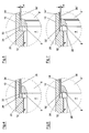
- FIG. 4 shows a first embodiment of the gas generator head 6 and its mode of operation during insertion into the gas generator chamber 12.
- the gas generator head 6 has a cutting edge 32 which is formed in the region of the insertion 8 pointing in the insertion direction.
- the cutting edge 32 thus points in the insertion direction and also extends along the circumference of the gas generator head 6. This is a circumferential cutting edge 32, so that it is irrelevant in which rotational position of the gas generator 2 is introduced.
- the cutting edge 32 is formed integrally with the metallic gas generator head 6. In the example of FIG. 4, the cutting edge encloses an angle of 90 °.
- On the circumference of the gas generator head 6, a circumferential abutment portion 34 is further provided, wherein the abutment portion 34 is arranged in the radial direction at the same height as the cutting edge 32 and behind the cutting edge 32.
- the cutting edge 32 When inserting the gas generator 2 into the gas generator chamber 12, the cutting edge 32 now encounters the support ribs 26 on the face side, so that the cutting edge 32 cuts into the support ribs 26, which are preferably made of plastic and are integrally formed with the airbag housing 10, during insertion. In this way, the height of the support ribs 26 is reduced and a predetermined interference fit between the resulting cut surface 36 on the one hand and the abutment portion 34 on the other hand achieved.
- the peripheral projection 8 abuts the gas generator 8 on the peripheral projection 20 of the airbag housing 10
- the maximum insertion depth is reached, and the portion 4 of the gas generator 2 facing away from the insertion opening 14 can be moved by means of a screw extending through the bore 24. be attached frontally.
- the grasp Snap hook 30 the gas generator head 6 as soon as the maximum insertion depth is reached.
- Fig. 5 shows a second embodiment of the gas generator head 6, wherein the second embodiment of the first embodiment of FIG. 4 is similar, so that only the differences will be discussed below and the above description applies otherwise.
- the same reference numbers are used for the same or similar parts.
- the peripheral abutment portion 34' on the gas generator 2 in the radial direction is arranged further outwardly than the cutting edge 32.
- the second embodiment also cuts the support ribs 26 by the cutting edge 32, the support rib 26 is then pushed outwardly by the further outwardly disposed abutment portion 34 'to achieve a greater interference fit.
- Fig. 6 shows a third embodiment of the gas generator head 6 ", the third embodiment being similar to the first embodiment of Fig. 4, so that only the differences will be discussed below and the above description applies otherwise same reference numerals used.
- the cutting edge 32 'in the third embodiment includes an angle which is smaller than 90 °, whereby a particularly simple cutting of the support ribs 26 is made possible.
- the more acute angle is achieved here by a corresponding curvature within the circumferential projection 8 on the gas generator 2.
- Fig. 7 shows a fourth embodiment of the gas generator head 6 ''', the fourth embodiment of the third embodiment of FIG. 6 is similar, so that only the differences will be discussed below and the above description otherwise applies accordingly.
- the same reference numbers are used for the same or similar parts.
- the peripheral abutment portion 34' ' is arranged on the gas generator 2 in the radial direction further outward than the cutting edge 32'.
- the support ribs 26 are cut by the cutting edge 32 ', and moreover, the support rib 26 is then pressurized by the further outwardly disposed abutment portion 34' to achieve a greater interference fit.
- the embodiments of the gas generator head described with reference to FIGS. 4 to 7 can be realized, for example, simply with the aid of a sheet-metal shaped part whose edge or even flanged edge serves as the cutting edge and / or contact section.
Landscapes
- Engineering & Computer Science (AREA)
- Mechanical Engineering (AREA)
- Air Bags (AREA)
Applications Claiming Priority (1)
| Application Number | Priority Date | Filing Date | Title |
|---|---|---|---|
| DE102005049154A DE102005049154A1 (de) | 2005-10-14 | 2005-10-14 | Gasgenerator für eine Airbageinrichtung, Bauteilsatz mit einem solchen Gasgenerator und einem Airbaggehäuse und Verfahren zur Herstellung einer Airbageinrichtung |
Publications (2)
| Publication Number | Publication Date |
|---|---|
| EP1775175A1 true EP1775175A1 (fr) | 2007-04-18 |
| EP1775175B1 EP1775175B1 (fr) | 2008-06-25 |
Family
ID=37635662
Family Applications (1)
| Application Number | Title | Priority Date | Filing Date |
|---|---|---|---|
| EP06021238A Not-in-force EP1775175B1 (fr) | 2005-10-14 | 2006-10-10 | Génerateur de gaz pour un dispositif d'airbag, ensemble de construction avec un tel génerateur et un boîtier d'airbag et un procédé pour la fabrication d'un tel dispositif d'airbag. |
Country Status (3)
| Country | Link |
|---|---|
| EP (1) | EP1775175B1 (fr) |
| AT (1) | ATE399113T1 (fr) |
| DE (2) | DE102005049154A1 (fr) |
Citations (4)
| Publication number | Priority date | Publication date | Assignee | Title |
|---|---|---|---|---|
| US5620200A (en) * | 1995-10-31 | 1997-04-15 | Morton International, Inc. | Airbag module reaction canister endwall with airbag inflator mount |
| US5700028A (en) * | 1996-03-19 | 1997-12-23 | General Motors Corporation | Air bag module with energy absorbing mounting bracket |
| US6126191A (en) * | 1998-03-16 | 2000-10-03 | General Motors Corporation | Air bag module assembly |
| DE20112313U1 (de) * | 2001-07-26 | 2001-11-29 | TRW Occupant Restraint Systems GmbH & Co. KG, 73553 Alfdorf | Baugruppe aus zylindrischem Gasgenerator, Gehäuse und Halteteil |
Family Cites Families (2)
| Publication number | Priority date | Publication date | Assignee | Title |
|---|---|---|---|---|
| JP3178069B2 (ja) * | 1992-03-30 | 2001-06-18 | タカタ株式会社 | 助手席用エアバッグ装置のインフレータ取付構造 |
| DE29701337U1 (de) * | 1997-01-14 | 1997-03-20 | Petri Ag, 63743 Aschaffenburg | Anordnung zur Befestigung eines Gasgenerators, insbesondere eines Rohrgasgenerators in einem Gehäuse, insbesondere in einem Diffusor eines Airbagmoduls |
-
2005
- 2005-10-14 DE DE102005049154A patent/DE102005049154A1/de not_active Withdrawn
-
2006
- 2006-10-10 DE DE502006000978T patent/DE502006000978D1/de active Active
- 2006-10-10 AT AT06021238T patent/ATE399113T1/de not_active IP Right Cessation
- 2006-10-10 EP EP06021238A patent/EP1775175B1/fr not_active Not-in-force
Patent Citations (4)
| Publication number | Priority date | Publication date | Assignee | Title |
|---|---|---|---|---|
| US5620200A (en) * | 1995-10-31 | 1997-04-15 | Morton International, Inc. | Airbag module reaction canister endwall with airbag inflator mount |
| US5700028A (en) * | 1996-03-19 | 1997-12-23 | General Motors Corporation | Air bag module with energy absorbing mounting bracket |
| US6126191A (en) * | 1998-03-16 | 2000-10-03 | General Motors Corporation | Air bag module assembly |
| DE20112313U1 (de) * | 2001-07-26 | 2001-11-29 | TRW Occupant Restraint Systems GmbH & Co. KG, 73553 Alfdorf | Baugruppe aus zylindrischem Gasgenerator, Gehäuse und Halteteil |
Also Published As
| Publication number | Publication date |
|---|---|
| EP1775175B1 (fr) | 2008-06-25 |
| DE102005049154A1 (de) | 2007-05-31 |
| DE502006000978D1 (de) | 2008-08-07 |
| ATE399113T1 (de) | 2008-07-15 |
Similar Documents
| Publication | Publication Date | Title |
|---|---|---|
| DE102010002847A1 (de) | Blindniet mit einem Nietkörper aus Kunststoff | |
| DE102017108586B3 (de) | Scharnier für ein Schaltschrankgehäuse sowie ein entsprechendes Schaltschrankgehäuse und Montageverfahren | |
| EP3710711A1 (fr) | Dispositif de fixation et utilisation d'un dispositif de fixation | |
| EP3485175B1 (fr) | Insert et procédé servant à connecter un raccordement électrique à une paroi | |
| EP1598563B1 (fr) | Système de connexion | |
| EP2636911A1 (fr) | Agencement de fixation | |
| EP3110587B1 (fr) | Système de fixation destiné à une panne | |
| DE102008025428A1 (de) | Elektrische Anschlusseinrichtung und Verfahren zur Herstellung einer solchen | |
| DE19826897A1 (de) | Schloß für Laufschaufeln eines Turbinenläufers | |
| DE10215608B4 (de) | Rohrverbinder | |
| EP1775175B1 (fr) | Génerateur de gaz pour un dispositif d'airbag, ensemble de construction avec un tel génerateur et un boîtier d'airbag et un procédé pour la fabrication d'un tel dispositif d'airbag. | |
| EP1866549B1 (fr) | Manchon et element muni d'un tel manchon | |
| DE10257818A1 (de) | Stutzen für eine Behälterwand | |
| EP2779323A1 (fr) | Dispositif de fixation pour raccords de câbles | |
| DE102016203142A1 (de) | Befestigungsstecker, Anbauteilbaugruppe, Anbauteilanordnung | |
| DE102012211778A1 (de) | Beschlaganordnung | |
| DE102013020801B4 (de) | Verfahren zum Fügen wenigstens zweier Bauteile mittels einer Fließformniethülse | |
| DE102013205948B4 (de) | Sicherungssystem und Verfahren zur Sicherung eines Befestigungsbereichs wenigstens einer Rotorschaufel oder eines Rotorschaufelsegments in einem Montagebereich eines Rotorgrundkörpers | |
| DE102013004044A1 (de) | Vorrichtung und Verfahren zur Befestigung eines Baukörpers in einer von einer Auflagefläche begrenzten Öffnung | |
| EP2148099A1 (fr) | Élément d'ancrage | |
| DE10328692A1 (de) | Verbindungselement zur festen jedoch lösbaren Verbindung eines Montageteils mit einem zweiten Bauteil | |
| EP3988803B1 (fr) | Unité fonctionnelle pourvue d'élément de connexion et d'élément de fixation | |
| EP4056863B1 (fr) | Élément fonctionnel | |
| DE10322728B3 (de) | Befestigungseinrichtung | |
| DE102024110315A1 (de) | Straffvorrichtung für eine Sicherheitsgurtkomponente und Verfahren zur Herstellung einer Straffvorrichtung |
Legal Events
| Date | Code | Title | Description |
|---|---|---|---|
| PUAI | Public reference made under article 153(3) epc to a published international application that has entered the european phase |
Free format text: ORIGINAL CODE: 0009012 |
|
| AK | Designated contracting states |
Kind code of ref document: A1 Designated state(s): AT BE BG CH CY CZ DE DK EE ES FI FR GB GR HU IE IS IT LI LT LU LV MC NL PL PT RO SE SI SK TR |
|
| AX | Request for extension of the european patent |
Extension state: AL BA HR MK YU |
|
| 17P | Request for examination filed |
Effective date: 20071018 |
|
| 17Q | First examination report despatched |
Effective date: 20071115 |
|
| AKX | Designation fees paid |
Designated state(s): AT BE BG CH CY CZ DE DK EE ES FI FR GB GR HU IE IS IT LI LT LU LV MC NL PL PT RO SE SI SK TR |
|
| GRAP | Despatch of communication of intention to grant a patent |
Free format text: ORIGINAL CODE: EPIDOSNIGR1 |
|
| GRAS | Grant fee paid |
Free format text: ORIGINAL CODE: EPIDOSNIGR3 |
|
| GRAA | (expected) grant |
Free format text: ORIGINAL CODE: 0009210 |
|
| AK | Designated contracting states |
Kind code of ref document: B1 Designated state(s): AT BE BG CH CY CZ DE DK EE ES FI FR GB GR HU IE IS IT LI LT LU LV MC NL PL PT RO SE SI SK TR |
|
| REG | Reference to a national code |
Ref country code: GB Ref legal event code: FG4D Free format text: NOT ENGLISH |
|
| REG | Reference to a national code |
Ref country code: CH Ref legal event code: EP |
|
| REF | Corresponds to: |
Ref document number: 502006000978 Country of ref document: DE Date of ref document: 20080807 Kind code of ref document: P |
|
| REG | Reference to a national code |
Ref country code: IE Ref legal event code: FG4D Free format text: LANGUAGE OF EP DOCUMENT: GERMAN |
|
| PG25 | Lapsed in a contracting state [announced via postgrant information from national office to epo] |
Ref country code: SI Free format text: LAPSE BECAUSE OF FAILURE TO SUBMIT A TRANSLATION OF THE DESCRIPTION OR TO PAY THE FEE WITHIN THE PRESCRIBED TIME-LIMIT Effective date: 20080625 Ref country code: FI Free format text: LAPSE BECAUSE OF FAILURE TO SUBMIT A TRANSLATION OF THE DESCRIPTION OR TO PAY THE FEE WITHIN THE PRESCRIBED TIME-LIMIT Effective date: 20080625 |
|
| PG25 | Lapsed in a contracting state [announced via postgrant information from national office to epo] |
Ref country code: PL Free format text: LAPSE BECAUSE OF FAILURE TO SUBMIT A TRANSLATION OF THE DESCRIPTION OR TO PAY THE FEE WITHIN THE PRESCRIBED TIME-LIMIT Effective date: 20080625 Ref country code: LV Free format text: LAPSE BECAUSE OF FAILURE TO SUBMIT A TRANSLATION OF THE DESCRIPTION OR TO PAY THE FEE WITHIN THE PRESCRIBED TIME-LIMIT Effective date: 20080625 Ref country code: NL Free format text: LAPSE BECAUSE OF FAILURE TO SUBMIT A TRANSLATION OF THE DESCRIPTION OR TO PAY THE FEE WITHIN THE PRESCRIBED TIME-LIMIT Effective date: 20080625 |
|
| NLV1 | Nl: lapsed or annulled due to failure to fulfill the requirements of art. 29p and 29m of the patents act | ||
| PG25 | Lapsed in a contracting state [announced via postgrant information from national office to epo] |
Ref country code: LT Free format text: LAPSE BECAUSE OF FAILURE TO SUBMIT A TRANSLATION OF THE DESCRIPTION OR TO PAY THE FEE WITHIN THE PRESCRIBED TIME-LIMIT Effective date: 20080625 Ref country code: CZ Free format text: LAPSE BECAUSE OF FAILURE TO SUBMIT A TRANSLATION OF THE DESCRIPTION OR TO PAY THE FEE WITHIN THE PRESCRIBED TIME-LIMIT Effective date: 20080625 Ref country code: SE Free format text: LAPSE BECAUSE OF FAILURE TO SUBMIT A TRANSLATION OF THE DESCRIPTION OR TO PAY THE FEE WITHIN THE PRESCRIBED TIME-LIMIT Effective date: 20080925 Ref country code: IS Free format text: LAPSE BECAUSE OF FAILURE TO SUBMIT A TRANSLATION OF THE DESCRIPTION OR TO PAY THE FEE WITHIN THE PRESCRIBED TIME-LIMIT Effective date: 20081025 |
|
| PG25 | Lapsed in a contracting state [announced via postgrant information from national office to epo] |
Ref country code: PT Free format text: LAPSE BECAUSE OF FAILURE TO SUBMIT A TRANSLATION OF THE DESCRIPTION OR TO PAY THE FEE WITHIN THE PRESCRIBED TIME-LIMIT Effective date: 20081125 Ref country code: RO Free format text: LAPSE BECAUSE OF FAILURE TO SUBMIT A TRANSLATION OF THE DESCRIPTION OR TO PAY THE FEE WITHIN THE PRESCRIBED TIME-LIMIT Effective date: 20080625 Ref country code: SK Free format text: LAPSE BECAUSE OF FAILURE TO SUBMIT A TRANSLATION OF THE DESCRIPTION OR TO PAY THE FEE WITHIN THE PRESCRIBED TIME-LIMIT Effective date: 20080625 Ref country code: ES Free format text: LAPSE BECAUSE OF FAILURE TO SUBMIT A TRANSLATION OF THE DESCRIPTION OR TO PAY THE FEE WITHIN THE PRESCRIBED TIME-LIMIT Effective date: 20081006 |
|
| REG | Reference to a national code |
Ref country code: IE Ref legal event code: FD4D |
|
| REG | Reference to a national code |
Ref country code: GB Ref legal event code: 732E Free format text: REGISTERED BETWEEN 20090305 AND 20090311 |
|
| BERE | Be: lapsed |
Owner name: GM GLOBAL TECHNOLOGY OPERATIONS, INC. Effective date: 20081031 |
|
| PG25 | Lapsed in a contracting state [announced via postgrant information from national office to epo] |
Ref country code: IE Free format text: LAPSE BECAUSE OF FAILURE TO SUBMIT A TRANSLATION OF THE DESCRIPTION OR TO PAY THE FEE WITHIN THE PRESCRIBED TIME-LIMIT Effective date: 20080625 Ref country code: EE Free format text: LAPSE BECAUSE OF FAILURE TO SUBMIT A TRANSLATION OF THE DESCRIPTION OR TO PAY THE FEE WITHIN THE PRESCRIBED TIME-LIMIT Effective date: 20080625 Ref country code: DK Free format text: LAPSE BECAUSE OF FAILURE TO SUBMIT A TRANSLATION OF THE DESCRIPTION OR TO PAY THE FEE WITHIN THE PRESCRIBED TIME-LIMIT Effective date: 20080625 Ref country code: BG Free format text: LAPSE BECAUSE OF FAILURE TO SUBMIT A TRANSLATION OF THE DESCRIPTION OR TO PAY THE FEE WITHIN THE PRESCRIBED TIME-LIMIT Effective date: 20080925 |
|
| PLBE | No opposition filed within time limit |
Free format text: ORIGINAL CODE: 0009261 |
|
| STAA | Information on the status of an ep patent application or granted ep patent |
Free format text: STATUS: NO OPPOSITION FILED WITHIN TIME LIMIT |
|
| PG25 | Lapsed in a contracting state [announced via postgrant information from national office to epo] |
Ref country code: MC Free format text: LAPSE BECAUSE OF NON-PAYMENT OF DUE FEES Effective date: 20081031 |
|
| 26N | No opposition filed |
Effective date: 20090326 |
|
| PG25 | Lapsed in a contracting state [announced via postgrant information from national office to epo] |
Ref country code: IT Free format text: LAPSE BECAUSE OF FAILURE TO SUBMIT A TRANSLATION OF THE DESCRIPTION OR TO PAY THE FEE WITHIN THE PRESCRIBED TIME-LIMIT Effective date: 20080625 |
|
| PG25 | Lapsed in a contracting state [announced via postgrant information from national office to epo] |
Ref country code: BE Free format text: LAPSE BECAUSE OF NON-PAYMENT OF DUE FEES Effective date: 20081031 |
|
| REG | Reference to a national code |
Ref country code: GB Ref legal event code: 732E Free format text: REGISTERED BETWEEN 20091029 AND 20091104 |
|
| REG | Reference to a national code |
Ref country code: GB Ref legal event code: 732E Free format text: REGISTERED BETWEEN 20091105 AND 20091111 |
|
| PG25 | Lapsed in a contracting state [announced via postgrant information from national office to epo] |
Ref country code: AT Free format text: LAPSE BECAUSE OF NON-PAYMENT OF DUE FEES Effective date: 20081010 |
|
| PG25 | Lapsed in a contracting state [announced via postgrant information from national office to epo] |
Ref country code: LU Free format text: LAPSE BECAUSE OF NON-PAYMENT OF DUE FEES Effective date: 20081010 Ref country code: HU Free format text: LAPSE BECAUSE OF FAILURE TO SUBMIT A TRANSLATION OF THE DESCRIPTION OR TO PAY THE FEE WITHIN THE PRESCRIBED TIME-LIMIT Effective date: 20081226 Ref country code: CY Free format text: LAPSE BECAUSE OF FAILURE TO SUBMIT A TRANSLATION OF THE DESCRIPTION OR TO PAY THE FEE WITHIN THE PRESCRIBED TIME-LIMIT Effective date: 20080625 |
|
| PG25 | Lapsed in a contracting state [announced via postgrant information from national office to epo] |
Ref country code: TR Free format text: LAPSE BECAUSE OF FAILURE TO SUBMIT A TRANSLATION OF THE DESCRIPTION OR TO PAY THE FEE WITHIN THE PRESCRIBED TIME-LIMIT Effective date: 20080625 |
|
| PG25 | Lapsed in a contracting state [announced via postgrant information from national office to epo] |
Ref country code: GR Free format text: LAPSE BECAUSE OF FAILURE TO SUBMIT A TRANSLATION OF THE DESCRIPTION OR TO PAY THE FEE WITHIN THE PRESCRIBED TIME-LIMIT Effective date: 20080926 |
|
| REG | Reference to a national code |
Ref country code: DE Ref legal event code: R081 Ref document number: 502006000978 Country of ref document: DE Owner name: GM GLOBAL TECHNOLOGY OPERATIONS LLC (N. D. GES, US Free format text: FORMER OWNER: GM GLOBAL TECHNOLOGY OPERATIONS, INC., DETROIT, MICH., US Effective date: 20110323 |
|
| REG | Reference to a national code |
Ref country code: CH Ref legal event code: PL |
|
| PG25 | Lapsed in a contracting state [announced via postgrant information from national office to epo] |
Ref country code: CH Free format text: LAPSE BECAUSE OF NON-PAYMENT OF DUE FEES Effective date: 20101031 Ref country code: LI Free format text: LAPSE BECAUSE OF NON-PAYMENT OF DUE FEES Effective date: 20101031 |
|
| PGFP | Annual fee paid to national office [announced via postgrant information from national office to epo] |
Ref country code: FR Payment date: 20121018 Year of fee payment: 7 Ref country code: DE Payment date: 20121003 Year of fee payment: 7 |
|
| PGFP | Annual fee paid to national office [announced via postgrant information from national office to epo] |
Ref country code: GB Payment date: 20121010 Year of fee payment: 7 |
|
| GBPC | Gb: european patent ceased through non-payment of renewal fee |
Effective date: 20131010 |
|
| PG25 | Lapsed in a contracting state [announced via postgrant information from national office to epo] |
Ref country code: GB Free format text: LAPSE BECAUSE OF NON-PAYMENT OF DUE FEES Effective date: 20131010 |
|
| REG | Reference to a national code |
Ref country code: FR Ref legal event code: ST Effective date: 20140630 |
|
| REG | Reference to a national code |
Ref country code: DE Ref legal event code: R119 Ref document number: 502006000978 Country of ref document: DE Effective date: 20140501 |
|
| PG25 | Lapsed in a contracting state [announced via postgrant information from national office to epo] |
Ref country code: FR Free format text: LAPSE BECAUSE OF NON-PAYMENT OF DUE FEES Effective date: 20131031 Ref country code: DE Free format text: LAPSE BECAUSE OF NON-PAYMENT OF DUE FEES Effective date: 20140501 |