EP1775183A2 - Pretensionneur de ceinture de sécurité - Google Patents
Pretensionneur de ceinture de sécurité Download PDFInfo
- Publication number
- EP1775183A2 EP1775183A2 EP06121029A EP06121029A EP1775183A2 EP 1775183 A2 EP1775183 A2 EP 1775183A2 EP 06121029 A EP06121029 A EP 06121029A EP 06121029 A EP06121029 A EP 06121029A EP 1775183 A2 EP1775183 A2 EP 1775183A2
- Authority
- EP
- European Patent Office
- Prior art keywords
- belt tensioner
- sleeve
- region
- shaft
- shaft unit
- Prior art date
- Legal status (The legal status is an assumption and is not a legal conclusion. Google has not performed a legal analysis and makes no representation as to the accuracy of the status listed.)
- Withdrawn
Links
Images



Classifications
-
- B—PERFORMING OPERATIONS; TRANSPORTING
- B60—VEHICLES IN GENERAL
- B60R—VEHICLES, VEHICLE FITTINGS, OR VEHICLE PARTS, NOT OTHERWISE PROVIDED FOR
- B60R22/00—Safety belts or body harnesses in vehicles
- B60R22/34—Belt retractors, e.g. reels
- B60R22/46—Reels with means to tension the belt in an emergency by forced winding up
- B60R22/4628—Reels with means to tension the belt in an emergency by forced winding up characterised by fluid actuators, e.g. pyrotechnic gas generators
-
- B—PERFORMING OPERATIONS; TRANSPORTING
- B60—VEHICLES IN GENERAL
- B60R—VEHICLES, VEHICLE FITTINGS, OR VEHICLE PARTS, NOT OTHERWISE PROVIDED FOR
- B60R22/00—Safety belts or body harnesses in vehicles
- B60R22/34—Belt retractors, e.g. reels
- B60R22/46—Reels with means to tension the belt in an emergency by forced winding up
- B60R22/4628—Reels with means to tension the belt in an emergency by forced winding up characterised by fluid actuators, e.g. pyrotechnic gas generators
- B60R2022/4642—Reels with means to tension the belt in an emergency by forced winding up characterised by fluid actuators, e.g. pyrotechnic gas generators the gas directly propelling a flexible driving means, e.g. a plurality of successive masses, in a tubular chamber
- B60R2022/4647—Reels with means to tension the belt in an emergency by forced winding up characterised by fluid actuators, e.g. pyrotechnic gas generators the gas directly propelling a flexible driving means, e.g. a plurality of successive masses, in a tubular chamber the driving means being a belt, a chain or the like
-
- B—PERFORMING OPERATIONS; TRANSPORTING
- B60—VEHICLES IN GENERAL
- B60R—VEHICLES, VEHICLE FITTINGS, OR VEHICLE PARTS, NOT OTHERWISE PROVIDED FOR
- B60R22/00—Safety belts or body harnesses in vehicles
- B60R22/34—Belt retractors, e.g. reels
- B60R22/46—Reels with means to tension the belt in an emergency by forced winding up
- B60R2022/468—Reels with means to tension the belt in an emergency by forced winding up characterised by clutching means between actuator and belt reel
Definitions
- the invention relates to a belt tensioner for a motor vehicle according to the preamble of claim 1.
- Such belt tensioners serve to tighten safety belts of motor vehicles in the event of a dangerous situation, for example a collision with another motor vehicle.
- Known belt tensioners have a belt reel rotatably mounted about an axis of rotation, which serves to wind the seat belt, and connected to the belt reel shaft unit which is connectable to the belt reel, that a rotational movement of the shaft unit is transferable to the belt reel.
- the belt reel can therefore be driven, that is, rotated.
- a longitudinally extending, flexible element is provided which on the one hand has a first region which is wound around the shaft unit and on the other hand has a second region which protrudes from the shaft unit and which is connected to the first region.
- the elongate member cooperates with the shaft unit to rotate in a first direction to tighten the seat belt when the first portion of the elongate member is unwound from the shaft unit by a tensile force applied to the second portion.
- This traction is provided in case of danger by a movement generating device, which may be, for example, a pyrotechnic movement generating device such as a gas generator.
- the invention is based on the problem, a belt tensioner of the type mentioned in such a way that a cost-effective and Malawiader belt tensioner is created.
- the first region of the longitudinally extending element is fixed with a partial section via a force-releasable connection on a not rotatable together with the shaft unit part, that the first region of the longitudinally extending element by acting on the second region tensile force (transverse to the first direction) is pressed against the shaft unit, and that after a release of the connection, the first portion of the elongate member along the first direction of the shaft unit is unwound, wherein the shaft unit is rotated to tighten the seat belt along the first direction.
- the shaft unit has at least one shaft element which is non-rotatably connected to the belt reel.
- the shaft unit may be in the form of a one-piece shaft member that is rotated together with the belt reel connected to the shaft member when the elongated member which has contracted around the shaft member as a result of the tensile force acting on the second portion of the elongate member Releasing the connection due to the tensile force is unwound from the shaft member.
- Under a one-piece shaft element is in this case understood a shaft member whose components rotate together with the belt reel.
- the shaft unit may comprise a shaft member in the form of a shaft core aligned with the rotation axis, which is rotatably connected to the belt reel and a rotatably mounted on the shaft core sleeve which is rotatably connected to the shaft core, when the longitudinally extending element due to the traction transverse to the first direction presses against the sleeve, wherein after a release of the compound, the elongate member is wrapped around the sleeve so tightly that the sleeve is rotated together with the shaft core along the first direction when the longitudinally extending member of the sleeve of the shaft unit is handled.
- the elongate member Before engaging the tensile force on the second portion of the elongate member, the elongate member is wrapped around the shaft unit with play, that is, in a one-piece shaft member shaft unit, the elongated member is initially wound around the shaft member such that rotation of the shaft member Shaft element is not affected.
- the longitudinally extending member is wrapped around the sleeve prior to engaging the tensile force on the second portion of the elongate member such that it does not obstruct rotational movement of the shaft core about its axis of rotation.
- connection is designed such that it is released by the tensile force, if this exceeds a predeterminable threshold. It is hereby conceivable to solve the connection non-destructively by means of the tensile force or to sever the connection by means of the tensile force in such a way that it is thereby destroyed.
- the connection preferably has at least one predetermined breaking point along which it can be severed.
- the first portion of the elongated member is urged against the shaft unit transversely to the first direction by the tensile force acting on the second portion, i.e. along a direction perpendicular to the axis of rotation.
- the shaft unit comprises at least the one shaft core and the shaft core the first direction encompassing sleeve is formed, which is rotatably mounted on the shaft core.
- the belt reel is rotatably mounted over the shaft core, that is, the shaft core is rotatably connected to the belt reel and rotatably mounted about an axis of rotation, wherein preferably the shaft core is aligned with the axis of rotation.
- the sleeve is arranged transversely to the first direction between the shaft core and the longitudinally extending element. That is, the first portion of the elongated member is wound around the sleeve surrounding the shaft core.
- the sleeve of the shaft unit is in this case designed such that it is non-rotatably connectable to the shaft core of the sleeve, when the tensile force generated by the movement generating device in case of danger, the first portion of the longitudinally extending element transverse to the first direction against the sleeve of the shaft unit.
- the sleeve acts as an intermediate element, over which the first region of the longitudinally extending element is pressed against the shaft core.
- the shaft unit is formed as the one-piece shaft member rotatably connected to the belt roll, which is preferably aligned with the axis of rotation, preferably the longitudinally extending member is wound directly around the shaft member and rotatably connected to the one-piece shaft member, ie , engages tightly around the shaft member when the tensile force generated by the motion generating device in the event of danger engages the first portion of the elongate member.
- the sleeve along the first direction is not self-contained (annular) formed, but slotted, ie, the sleeve has a slot along the axis of rotation, which causes the sleeve (for producing a rotationally fixed connection between the sleeve and shaft core) is transversely deformed easier to deform in the first direction.
- connection is formed by at least one connecting element which is fastened to the sleeve of the shaft unit and connects it to the part of the belt tensioner which is not rotatable with the shaft unit, wherein preferably the connecting element is made in one piece with the sleeve of the shaft unit is formed.
- the at least one connecting element is fastened to a portion of the elongated element which is wound around the shaft unit, that is to say at the first region of the longitudinally extending element.
- at least one connecting element integrally formed on the first region.
- connection has a further connecting element which preferably aligns with the at least one connecting element.
- the second region of the elongated member projecting from the shaft assembly along the first direction is formed as a loop, which may be of any shape. This can be created by placing the elongate member in a loop prior to being wound on the sleeve of the shaft unit (or alternatively the shaft unit in the form of the one-piece shaft member) so that first and second free end portions of the longitudinally extended one Element abut each other and are connected to each other via a central portion of the longitudinally extending element, which forms the second region of the longitudinally extending element.
- the first region is preferably connected in one piece with the first region.
- the first portion of the elongated member is wrapped around the shaft unit such that both the first and second end portions completely orbit at least twice about the shaft unit.
- the one of the The first and second end portions are preferably in the range of 720 ° to 900 °.
- the two end portions are here transversely to the first direction above the other.
- the first region of the longitudinally extending element can be fixed to the sleeve.
- the sleeve has at least one recess facing away from the shaft core, which may extend groove-like along the axis of rotation, wherein preferably the first portion of the longitudinally extending element for fixing the longitudinally extending element on the sleeve with at least one free end in the at least one recess Sleeve engages.
- a free end of the first and the second end portion of the longitudinally extending element to be suitable for engaging in the recess of the sleeve to be angled.
- the longitudinally extending element is flat, strip-shaped. Furthermore, the longitudinally extending element is preferably made of a metal, that is to say that the longitudinally extending element is thus preferably a flat metal strip.
- the second region of the longitudinally extending element surrounds a pressurizable volume such that pressurizing the volume by means of the motion generating device generates the tensile force unwinding the first region from the shaft assembly.
- the movement generating device may be formed as a gas generator, which releases a gas in case of danger, the gas pressure provides the required for unwinding the first portion of the elongated member traction.
- the tensile force provided by the motion generating device may be composed of a plurality of individual tensile forces introduced via the second region into the first region, i.e., the portion of the elongate member wound on the shaft assembly.
- the belt tensioner according to the invention has a first and second housing wall oriented transversely to the axis of rotation, wherein the first and the second housing wall along the axis of rotation opposite each other and extend substantially parallel to each other.
- the two housing walls serve together with the second region of the longitudinally extending element for enclosing the pressurizable volume of the belt tensioner.
- the part of the belt tensioner which is not rotatable together with the shaft unit and to which the connection is connected, is preferably formed by the first and / or second housing wall.
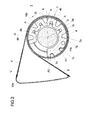
- FIG. 1 shows, in conjunction with FIG. 2, a schematic, sectional view of a belt tensioner 1 with a belt reel (not shown in FIG. 1) for winding up a safety belt of a motor vehicle (not shown in FIG. 1), which is connected to a shaft unit 2; which is composed of a cast on the belt reel shaft 3 and a pushed onto the shaft core 3 sleeve 4.
- the shaft core 3 together with the belt reel attached thereto is rotatably mounted about a rotation axis D, wherein the belt reel and the shaft core 3 are formed cylindrically symmetrical to the rotation axis D.
- a radial bearing 5 is provided, which in a at a free end 3 c of Shaft core 3 trained aligned with the rotation axis D recess 5a engages and a thrust bearing 6, the pot-like surrounding the free end 3c of the shaft core 3 and engages in an annular groove of the shaft core 3, the shaft core 3 at its free end 3c transverse to the axis of rotation D. circulates.
- the sleeve 4 encompassing the shaft core 3 is designed to be open along the first direction R, ie, the sleeve 4 does not completely encircle the shaft core 3 along the first direction R and furthermore has an inner diameter such that the shaft core 3 in the sleeve 4 surrounds the rotation axis D can rotate. That is, the inner diameter of the sleeve 4 is larger than the outer diameter of the shaft core 3.
- the sleeve 4 is resiliently formed transversely to the first direction R, ie, the sleeve 4 can be deformed by a force acting on the sleeve 4 transversely to the first direction R force in that a rotationally fixed connection is made between an inner side 4a of the sleeve 4 facing the shaft core 3 and an outer side 3a of the shaft core 3 extending along the axis of rotation D.
- the sleeve 4 also has the outer side 3a of the shaft core 3 facing groove-shaped inner recesses 4b, so that the surface with which the inside 4a of the sleeve 4 can rest against the outside 3a of the shaft core 3, is effectively reduced. As a result, a contact pressure which the sleeve 4 exerts on the shaft core 3 can be increased.
- a strip-shaped formed longitudinally extending element 7 along a sleeve 4 and the shaft core 3 annular circumferential direction R is wound, in such a way that it rotates the sleeve 4 at least once, preferably more than once completely along the first direction R.
- the longitudinally extending element 7 is arranged together with sleeve 4 along the axis of rotation D between a first and a second housing wall 8, 9 of the belt tensioner 1, wherein the first housing wall 8 and the second housing wall 9 each have a recess 8a, 9a, which along the Are opposite axis of rotation D and the storage of the shaft core 3 serve.
- the thrust bearing 6 is fitted, which surrounds the free end 3c of the shaft core 3 like a pot.
- the recess 9a of the second housing wall 9, which is arranged along the axis of rotation D between the sleeve 4 and the belt retractor, not shown is, on the outer side 3a of the shaft core 3 facing inner side 9a, which rotates the shaft core 3 along the first direction R and forms a sliding surface for the shaft core 3.
- the longitudinally extending element 7 has according to Figure 2 a first end portion 7a and a second end portion 7b, which together form a first portion 10b of the longitudinally extending element 7, wherein the first and the second end portion 7a, 7b of the longitudinally extending element 7 via a second area 10a of the longitudinally extending element 7 are interconnected.
- This second region 10a forms a loop of any shape that protrudes from the sleeve 4 and surrounds a pressurizable volume V, which by the second portion 10a of the elongated member 7 on the one hand and the two perpendicular to the rotation axis D extending housing walls 8, 9 on the other is enclosed.
- the first end portion 7a and the second end portion 7b of the elongated member 7, which together form the first portion 10b of the elongated member 7, are wound around the sleeve 4 so as to be substantially congruent to each other across the first direction R. , Wherein the first end portion 7a rests with a partial section on an outer side 4c of the sleeve 4 facing away from the shaft core 3.
- the partial section of the first section 7a of the longitudinally extending element 7 resting on the outer side 4c of the sleeve 4 has an angled free end 7c which engages in a recess A1 of a plurality of recesses A for fixing the first section 7a of the longitudinally extending element 7, which are groove-shaped along the axis of rotation D on the longitudinally extending member 7 facing outside 4c of the sleeve 4 are formed. So that the second end portion 7b of the longitudinally extending element 7 can engage with a free end 7d in a further recess A2 adjacent to the recess A1, the second end portion 7b projects beyond the first end portion 7a along the first direction R.
- the angled free end 7d of the second end portion 7b engage in the further recess A2, whereby the second end portions 7b of the longitudinally extending element 7 is fixed to the sleeve 4.
- Decisive with respect to the engagement of the two free ends 7c, 7d in the recesses A is that the two free ends 7c, 7d can be brought out of engagement with the recesses A only by a movement oriented transversely to the first direction.
- the recesses A as passage openings which extend transversely to the first direction R through the sleeve 4.
- the free ends 7c, 7d of the first and second end portions 7a, 7b can be passed through in each case such a recess A and are fixed with appropriate shaping on the inside 4a of the sleeve 4.
- the volume V is pressurized.
- a movement generating device in the form of a gas generator can release a gas which is introduced into the volume V and exerts a tensile force on the second region 10a of the longitudinally extending element 7 surrounding the volume.
- the second region 10a of the longitudinally extending element 7, ie, that part of a wall of the volume V, which is located along the axis of rotation D between the first and the second housing wall 8, 9 of the belt tensioner 1, is arranged such that the pressure applied by the pressure resulting tensile force is composed of a first tensile component F and a second tensile component E, wherein the two tensile components E, F include an angle and tangentially introduced along the first direction R in the wound around the sleeve 4 first portion 10 b of the elongated member 7.
- the provided by the movement generating device tensile force or the two tensile components E, F unwinding of the first portion 10a of the sleeve 4 result, in such a way that thereby the shaft core 3 and thus the belt reel to tighten the seat belt in the first Turn direction R, before the unwinding of the first portion 10b of the elongated member 7 of the sleeve 4, a sufficiently large radial force the first portion 10b of the elongated member 7 transverse to the first direction R press against the sleeve 4, which then so transversely to the first direction R is pressed against the shaft core 3, that a rotationally fixed connection between the first portion 10 b and the sleeve 4 on the one hand and the sleeve 4 and the shaft core 3 on the other hand is created.
- the sleeve 4 is connected via a first and a second connecting element 11a, 11b with the two housing walls 8, 9 of the belt tensioner 1, so that the sleeve 4 due to the in the first region 10b Initially introduced tensile force components E, F along the first direction R can not rotate initially.
- the two connecting elements 11a, 11b are each designed as shear pins which project along the axis of rotation D from sides of the sleeve 4 facing away from each other along the axis of rotation D and in each case engage in corresponding recesses of the first or second housing wall 8, 9 and thus prevent the sleeve 4 can rotate about the axis of rotation D along the first direction R.
- additional, additional connecting elements may be provided. This may be particularly advantageous in the production of the belt tensioner 1, since by means of such additional connecting elements between the sleeve 4 and a not rotatable with the sleeve 4 part of the belt tensioner 1, the sleeve 4 can be additionally fixed during manufacture, whereby the assembly of the belt tensioner 1 is facilitated.
- FIG. 2 a shows, in connection with FIGS. 2 b-d, a schematic sectional view of a belt tensioner 1 of the type shown in FIG. 1 or FIG. 2 after the movement-generating device has pressurized the volume V.
- the two tensile force components E, F produced thereby which are introduced tangentially into the first region 10b of the longitudinally extending element 7 wound around the sleeve 4, cause the connection between the sleeve 4 and the two housing walls formed by the two connecting elements 11a, 11b 8, 9 (the first connecting element 11a is in the figure 2a as well as the two housing walls 8, 9 not shown) a torque, the sleeve 4 about an axis parallel to the axis of rotation D extending axis, which is aligned with the two connecting elements 11a, 11b , rotates, in the same direction with the first direction R.
- the sleeve 4 is deformed so that it is supported on a portion of the outer side 3a of the shaft core 3, ie, the two shear pins 11a, 11b take together with the shaft core 3 the Counter forces to the two tensile components E, F on.
- the movement generating device is designed in such a way that the two tension components E, F exceed a threshold in terms of magnitude, that is is chosen that the connection between the sleeve 4 and the two housing walls 8, 9 of the belt tensioner 1 is released, ie, the two connecting elements 11 a, 11 b are transversely to the axis of rotation D tangentially by the tensile force components E, F and radially by the of Tensile force components E, F sheared radial force sheared off from the sleeve 4.
- This shearing process is continuous and ends with the complete shearing off of the two connecting elements 11a, 11b, which usually have a diameter of about 1 to 2 mm. This shearing process is shown schematically in FIG. 2c.
- a rotationally fixed connection between the sleeve 4 and the shaft core 3 is formed according to FIG. 2d.
- the amount of radial forces that the elongated member 7 exerts on the sleeve 4 due to the tensile forces E, F depends on how often the first portion 10b of the elongate member 7 is wound around the shaft core 3 and how great is the friction between them is the superposed portions of the elongated member 7.
- the radial forces acting transversely to the first direction R ensure that the first region 10b of the longitudinally extending element 7 presses the sleeve 4 against the shaft core 3 such that the unwinding of the first region 10b of the longitudinally extending element 7 is effected by the two tensile components E, F causes the shaft core 3 rotates in the first direction R and thus the seat belt is wound to tighten on the non-rotatably connected to the shaft core 3 belt reel.
- the two shear pins 11a, 11b are connected to one of the two end portions 7a, 7b of the first portion 10b. Furthermore, a definition of the first region 10b on the sleeve 4 is not absolutely necessary.
- the radial force provided by the tensile force components E, F (due to the connection between the sleeve 4 and the first portion 10b of the elongated member 7 and the housing walls 8, 9) is sufficient to cause the shaft core 3 to unwind during unwinding stretched longitudinally Element 7 of the shaft core 3 rotates in the first direction R as soon as the connection is released, ie, the two connecting elements 11 a, 11 b are sheared off.
Landscapes
- Engineering & Computer Science (AREA)
- Mechanical Engineering (AREA)
- Automotive Seat Belt Assembly (AREA)
Applications Claiming Priority (1)
| Application Number | Priority Date | Filing Date | Title |
|---|---|---|---|
| DE200510050300 DE102005050300B3 (de) | 2005-10-17 | 2005-10-17 | Gurtstraffer für ein Kraftfahrzeug |
Publications (2)
| Publication Number | Publication Date |
|---|---|
| EP1775183A2 true EP1775183A2 (fr) | 2007-04-18 |
| EP1775183A3 EP1775183A3 (fr) | 2007-06-06 |
Family
ID=37387954
Family Applications (1)
| Application Number | Title | Priority Date | Filing Date |
|---|---|---|---|
| EP06121029A Withdrawn EP1775183A3 (fr) | 2005-10-17 | 2006-09-21 | Pretensionneur de ceinture de sécurité |
Country Status (2)
| Country | Link |
|---|---|
| EP (1) | EP1775183A3 (fr) |
| DE (1) | DE102005050300B3 (fr) |
Family Cites Families (6)
| Publication number | Priority date | Publication date | Assignee | Title |
|---|---|---|---|---|
| EP0703125B1 (fr) * | 1994-09-13 | 1999-05-26 | TAKATA (EUROPE) VEHICLE SAFETY TECHNOLOGY GmbH | Tendeur pour dispositif de ceinture de sécurité dans les véhicules |
| DE19503150A1 (de) * | 1995-02-01 | 1996-08-08 | Takata Europ Gmbh | Einen Gurtstraffer aufweisende Sicherheitsgurtanordnung in Kraftfahrzeugen |
| DE19643402A1 (de) * | 1996-10-21 | 1998-04-30 | Michael Dipl Ing Mittnacht | Gurtstraffer für Gurtautomaten bei Kraftfahrzeugen |
| US5899399A (en) * | 1997-06-12 | 1999-05-04 | Trw Vehicle Safety Systems Inc. | Seat belt pretensioner |
| DE19961109B4 (de) * | 1999-12-17 | 2009-06-10 | Takata-Petri Ag | Sicherheitsgurtvorrichtung für Kraftfahrzeuge |
| DE10120019A1 (de) * | 2001-04-24 | 2002-10-31 | Takata Petri Gmbh Ulm | Antriebsbandfixierung |
-
2005
- 2005-10-17 DE DE200510050300 patent/DE102005050300B3/de not_active Expired - Fee Related
-
2006
- 2006-09-21 EP EP06121029A patent/EP1775183A3/fr not_active Withdrawn
Non-Patent Citations (1)
| Title |
|---|
| None |
Also Published As
| Publication number | Publication date |
|---|---|
| EP1775183A3 (fr) | 2007-06-06 |
| DE102005050300B3 (de) | 2006-11-30 |
Similar Documents
| Publication | Publication Date | Title |
|---|---|---|
| DE69712554T2 (de) | Sicherheitsgurtaufroller mit Energiekontrolle | |
| DE19826305C2 (de) | Sitzgurtvorspannvorrichtung | |
| DE602004000506T2 (de) | Sicherheitsgurt-Aufroller | |
| DE10108489A1 (de) | Sitzgurteinzieheinrichtung | |
| WO2013060439A1 (fr) | Tendeur de ceinture pour un système de ceinture de sécurité | |
| DE112017002901T5 (de) | Gurtaufwickelvorrichtung | |
| DE10119753A1 (de) | Gurtstraffer | |
| DE10024344A1 (de) | Kupplungsmechanismus | |
| DE60115579T2 (de) | Weich-Start-Betätigungskolben | |
| DE10010379B4 (de) | Sicherheitsgurtsystem | |
| DE4426479C2 (de) | Sicherheitsgurt-Rückhaltesystem | |
| WO2010060559A1 (fr) | Enrouleur de ceinture pourvu d'un dispositif limiteur d'effort | |
| DE69914842T2 (de) | Kupplungsvorrichtung zur Drehmomentübertragung | |
| DE19514090C2 (de) | Anschnallgurt-Wickelvorrichtung | |
| DE4135111A1 (de) | Energiewandler fuer einen sicherheitsgurt | |
| DE69106973T2 (de) | Sicherheitsgurtstrammer. | |
| DE102011117053A1 (de) | Gurtstraffer für ein Sicherheitsgurtsystem | |
| WO2013060440A1 (fr) | Tendeur à ferrure terminale pour un système de ceinture de sécurité | |
| EP0588262A1 (fr) | Procédé et dispositif pour tendre des ceintures de sécurité | |
| EP1775183A2 (fr) | Pretensionneur de ceinture de sécurité | |
| DE102010025714A1 (de) | Schnellverschluss für ein fahrzeugfestes Ende eines Sicherheitsgurtes in einem Kraftfahrzeug | |
| EP0778182A2 (fr) | Système de retenue dans un véhicule | |
| DE3328874C2 (fr) | ||
| DE102004057095B3 (de) | Gurtstraffer | |
| EP2285628A1 (fr) | Tendeur de ceinture muni d une bande métallique pour la transmission des forces |
Legal Events
| Date | Code | Title | Description |
|---|---|---|---|
| PUAI | Public reference made under article 153(3) epc to a published international application that has entered the european phase |
Free format text: ORIGINAL CODE: 0009012 |
|
| AK | Designated contracting states |
Kind code of ref document: A2 Designated state(s): AT BE BG CH CY CZ DE DK EE ES FI FR GB GR HU IE IS IT LI LT LU LV MC NL PL PT RO SE SI SK TR |
|
| AX | Request for extension of the european patent |
Extension state: AL BA HR MK YU |
|
| PUAL | Search report despatched |
Free format text: ORIGINAL CODE: 0009013 |
|
| AK | Designated contracting states |
Kind code of ref document: A3 Designated state(s): AT BE BG CH CY CZ DE DK EE ES FI FR GB GR HU IE IS IT LI LT LU LV MC NL PL PT RO SE SI SK TR |
|
| AX | Request for extension of the european patent |
Extension state: AL BA HR MK YU |
|
| 17P | Request for examination filed |
Effective date: 20071206 |
|
| AKX | Designation fees paid |
Designated state(s): DE FR GB SE |
|
| 17Q | First examination report despatched |
Effective date: 20090305 |
|
| STAA | Information on the status of an ep patent application or granted ep patent |
Free format text: STATUS: THE APPLICATION IS DEEMED TO BE WITHDRAWN |
|
| 18D | Application deemed to be withdrawn |
Effective date: 20090716 |