EP1775196A2 - Pivot de roue orientable pour un véhicule industriel, en particulier chariots élévateurs, tracteurs, remorques ou similaire - Google Patents
Pivot de roue orientable pour un véhicule industriel, en particulier chariots élévateurs, tracteurs, remorques ou similaire Download PDFInfo
- Publication number
- EP1775196A2 EP1775196A2 EP06118501A EP06118501A EP1775196A2 EP 1775196 A2 EP1775196 A2 EP 1775196A2 EP 06118501 A EP06118501 A EP 06118501A EP 06118501 A EP06118501 A EP 06118501A EP 1775196 A2 EP1775196 A2 EP 1775196A2
- Authority
- EP
- European Patent Office
- Prior art keywords
- assembly according
- supporting element
- motor shaft
- steering assembly
- tractors
- Prior art date
- Legal status (The legal status is an assumption and is not a legal conclusion. Google has not performed a legal analysis and makes no representation as to the accuracy of the status listed.)
- Withdrawn
Links
- 230000008878 coupling Effects 0.000 claims abstract description 10
- 238000010168 coupling process Methods 0.000 claims abstract description 10
- 238000005859 coupling reaction Methods 0.000 claims abstract description 10
- 230000033001 locomotion Effects 0.000 claims abstract description 8
- 230000005540 biological transmission Effects 0.000 claims abstract description 7
- 230000009467 reduction Effects 0.000 claims description 5
- 238000001514 detection method Methods 0.000 claims 3
- 230000000712 assembly Effects 0.000 description 6
- 238000000429 assembly Methods 0.000 description 6
- 239000012530 fluid Substances 0.000 description 2
- 230000000670 limiting effect Effects 0.000 description 2
- 238000004519 manufacturing process Methods 0.000 description 2
- 230000009471 action Effects 0.000 description 1
- 238000004500 asepsis Methods 0.000 description 1
- 230000003749 cleanliness Effects 0.000 description 1
- 238000003754 machining Methods 0.000 description 1
- 230000007257 malfunction Effects 0.000 description 1
- 239000000463 material Substances 0.000 description 1
- 230000004048 modification Effects 0.000 description 1
- 238000012986 modification Methods 0.000 description 1
- 238000004513 sizing Methods 0.000 description 1
- 239000000126 substance Substances 0.000 description 1
Images


Classifications
-
- B—PERFORMING OPERATIONS; TRANSPORTING
- B62—LAND VEHICLES FOR TRAVELLING OTHERWISE THAN ON RAILS
- B62D—MOTOR VEHICLES; TRAILERS
- B62D5/00—Power-assisted or power-driven steering
- B62D5/04—Power-assisted or power-driven steering electrical, e.g. using an electric servo-motor connected to, or forming part of, the steering gear
- B62D5/0418—Electric motor acting on road wheel carriers
-
- B—PERFORMING OPERATIONS; TRANSPORTING
- B62—LAND VEHICLES FOR TRAVELLING OTHERWISE THAN ON RAILS
- B62D—MOTOR VEHICLES; TRAILERS
- B62D15/00—Steering not otherwise provided for
- B62D15/02—Steering position indicators ; Steering position determination; Steering aids
- B62D15/021—Determination of steering angle
- B62D15/023—Determination of steering angle by measuring on the king pin
-
- B—PERFORMING OPERATIONS; TRANSPORTING
- B62—LAND VEHICLES FOR TRAVELLING OTHERWISE THAN ON RAILS
- B62D—MOTOR VEHICLES; TRAILERS
- B62D7/00—Steering linkage; Stub axles or their mountings
- B62D7/02—Steering linkage; Stub axles or their mountings for pivoted bogies
- B62D7/04—Steering linkage; Stub axles or their mountings for pivoted bogies with more than one wheel
-
- B—PERFORMING OPERATIONS; TRANSPORTING
- B62—LAND VEHICLES FOR TRAVELLING OTHERWISE THAN ON RAILS
- B62D—MOTOR VEHICLES; TRAILERS
- B62D7/00—Steering linkage; Stub axles or their mountings
- B62D7/06—Steering linkage; Stub axles or their mountings for individually-pivoted wheels, e.g. on king-pins
- B62D7/08—Steering linkage; Stub axles or their mountings for individually-pivoted wheels, e.g. on king-pins the pivotal axes being situated in a single plane transverse to the longitudinal centre line of the vehicle
Definitions
- the present invention relates to a steering assembly for work vehicles, particularly lift trucks, tractors, trailers and/or the like.
- work vehicles such as lift trucks, small tractors and others, provided with three or four wheels, have particular steering assemblies which are actuated hydromechanically and are used to turn, through predefined angles and in predefined times, the hub supporting shafts of one or more steerable wheels.
- These steering assemblies comprise a box-like body, which is generally cylindrical and accommodates a plurality of toothed couplings arranged in succession, which are constituted substantially by coaxial and mutually interacting gears designed to convert the reciprocating rectilinear motion of one or more pistons, produced by the action of a pressurized fluid, into a rotary motion of the hub supporting shaft.
- Steering assemblies are also known which are constituted by a pinion which is keyed to the hub supporting shaft and is coupled to a rack, the axial movements of which are determined by two hydraulic cylinders associated respectively with its opposite ends.
- Another type of steering assembly consists of a hydraulic jack, the piston of which is provided with transverse pins engaged slidingly within helical slots provided on the outer surface of a cylinder; the translational motion of the piston and of the pins rigidly coupled thereto makes the cylinder rotate about its own axis and turn the hub supporting shaft mounted on said cylinder.
- the aim of the present invention is to eliminate the above-mentioned drawbacks of the background art, by providing a steering assembly for work vehicles, particularly lift trucks, tractors, trailers and/or the like, which is constructively particularly simple, practical to provide and compact, and can be modified easily according to the performance to be obtained and can be used even in very clean environments.
- an object of the present invention is to provide a steering assembly which is simple, relatively easy to provide in practice, safe in use and effective in operation.
- the present steering assembly for work vehicles, particularly lift trucks, tractors, trailers and/or the like, which comprises a body for coupling to a work vehicle provided with means for rotation about a substantially vertical axis of at least one wheel hub supporting element, motor means for turning a motor shaft which can be associated with said coupling body and rotary motion transmission means which are interposed substantially between said motor shaft and said supporting element, characterized in that said motor means are of the electrical type.
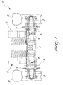
- the reference numeral 1 generally designates a steering assembly for work vehicles, particularly lift trucks, tractors, trailers and/or the like.
- the steering assembly 1 is used to steer a pair of wheels R mounted on opposite sides of a hub 2, which is associated centrally with a substantially vertical supporting element 3.
- the steering assembly 1 comprises a body 4 for coupling to the work vehicle, which is provided with means 5 for turning the supporting element 3 about a vertical axis A.
- Motor means 6 for turning a motor shaft 7 are mounted on the coupling body 4; said motor shaft is associated with the supporting element 3 by way of the interposition of rotary motion transmission means 8.
- the motor means 6 of the steering assembly 1 are of the electrical type and comprise a gearmotor constituted by a main motor 6a and by an output reduction unit 6b, from which the motor shaft 7 protrudes.
- the transmission means 8 comprise at least one reduction assembly provided with at least one portion of a gear 9, which is keyed to the supporting element 3, and at least one toothed pinion 10, which meshes with the gear 9 and can be keyed to the motor shaft 7.
- the reduction assembly is contained in at least one box-like body 11, which is associated with the coupling body 4 and inside which there are two conical roller bearings, which constitute the rotation means 5.
- Means for detecting the breadth of the rotation of the supporting element 3 about the vertical axis A are provided at the upper end of the supporting element 3; said means are of the electronic type and are constituted for example by a potentiometer 12.
- Figures 2, 3 and 4 illustrate, purely by way of example, a possible embodiment of the present invention applied to an axle for supporting two mutually opposite steerable wheels, such as those fitted on work vehicles with four or more wheels.
- the refinement of using motor means of the electrical type in fact allows to simplify considerably the structural architecture of the steering assembly, reduce the overall dimensions, increase the performance in terms of steering precision, and avoid the use of oil or other fluids, which might dirty the surrounding environment in case of leaks.
- the present invention can be adapted easily to steer wheels having different weights and dimensions.
Landscapes
- Engineering & Computer Science (AREA)
- Chemical & Material Sciences (AREA)
- Combustion & Propulsion (AREA)
- Transportation (AREA)
- Mechanical Engineering (AREA)
- Steering-Linkage Mechanisms And Four-Wheel Steering (AREA)
- Steering Control In Accordance With Driving Conditions (AREA)
- Automobile Manufacture Line, Endless Track Vehicle, Trailer (AREA)
- Guiding Agricultural Machines (AREA)
Applications Claiming Priority (1)
| Application Number | Priority Date | Filing Date | Title |
|---|---|---|---|
| ITMO20050258 ITMO20050258A1 (it) | 2005-10-11 | 2005-10-11 | Gruppo di sterzatura per macchine operatrici, particolarmente carrelli elevatori, trattori, rimorchi e o simili |
Publications (2)
| Publication Number | Publication Date |
|---|---|
| EP1775196A2 true EP1775196A2 (fr) | 2007-04-18 |
| EP1775196A3 EP1775196A3 (fr) | 2008-07-23 |
Family
ID=37560748
Family Applications (1)
| Application Number | Title | Priority Date | Filing Date |
|---|---|---|---|
| EP06118501A Withdrawn EP1775196A3 (fr) | 2005-10-11 | 2006-08-07 | Pivot de roue orientable pour un véhicule industriel, en particulier chariots élévateurs, tracteurs, remorques ou similaire |
Country Status (3)
| Country | Link |
|---|---|
| EP (1) | EP1775196A3 (fr) |
| CN (1) | CN1948041B (fr) |
| IT (1) | ITMO20050258A1 (fr) |
Cited By (4)
| Publication number | Priority date | Publication date | Assignee | Title |
|---|---|---|---|---|
| ITMO20100143A1 (it) * | 2010-05-12 | 2011-11-13 | Ivan Borghi | Gruppo di sterzatura per ruote di veicoli |
| ITMO20110094A1 (it) * | 2011-04-29 | 2012-10-30 | Ivan Borghi | Gruppo di sterzatura per ruote di veicoli |
| WO2013054339A3 (fr) * | 2011-07-08 | 2013-07-04 | Tata Motors Limited | Système de direction pour véhicule |
| IT202300021492A1 (it) * | 2023-10-16 | 2025-04-16 | Toyota Mat Handling Manufacturing Italy S P A | Carrello industriale con assale sterzante migliorato |
Families Citing this family (2)
| Publication number | Priority date | Publication date | Assignee | Title |
|---|---|---|---|---|
| DE102010015713A1 (de) * | 2010-04-21 | 2011-10-27 | Schaeffler Technologies Gmbh & Co. Kg | Bewegbares System |
| CN103448796A (zh) * | 2013-08-16 | 2013-12-18 | 杨鹏波 | 叉车转向桥 |
Citations (1)
| Publication number | Priority date | Publication date | Assignee | Title |
|---|---|---|---|---|
| DE10113775A1 (de) * | 2001-03-21 | 2002-09-26 | Linde Ag | Lenkantrieb mit einem Lenkmotor und einem Lenkgetriebe |
Family Cites Families (5)
| Publication number | Priority date | Publication date | Assignee | Title |
|---|---|---|---|---|
| IT1295191B1 (it) * | 1997-09-24 | 1999-05-04 | Marco Bettini | Dispositivo di controllo dell'angolo di sterzatura in autocarri od autoarticolati. |
| US6568696B2 (en) * | 2000-12-08 | 2003-05-27 | Clark Equipment Company | Kingpin angle mounted sensor |
| NL1018301C2 (nl) * | 2001-06-15 | 2002-12-17 | Skf Ab | Sensor in King-pin. |
| SE526090C2 (sv) * | 2002-08-14 | 2005-07-05 | Volvo Lastvagnar Ab | Styranordning, fordon och metod för att styra fordon |
| ITMO20030223A1 (it) * | 2003-07-31 | 2005-02-01 | Gaetani Angelo | Dispositivo di sterzatura. |
-
2005
- 2005-10-11 IT ITMO20050258 patent/ITMO20050258A1/it unknown
-
2006
- 2006-08-07 EP EP06118501A patent/EP1775196A3/fr not_active Withdrawn
- 2006-08-09 CN CN2006101111755A patent/CN1948041B/zh active Active
Patent Citations (1)
| Publication number | Priority date | Publication date | Assignee | Title |
|---|---|---|---|---|
| DE10113775A1 (de) * | 2001-03-21 | 2002-09-26 | Linde Ag | Lenkantrieb mit einem Lenkmotor und einem Lenkgetriebe |
Cited By (9)
| Publication number | Priority date | Publication date | Assignee | Title |
|---|---|---|---|---|
| ITMO20100143A1 (it) * | 2010-05-12 | 2011-11-13 | Ivan Borghi | Gruppo di sterzatura per ruote di veicoli |
| WO2011141794A2 (fr) | 2010-05-12 | 2011-11-17 | Ivan Borghi | Module de braquage pour roues de véhicule |
| WO2011141794A3 (fr) * | 2010-05-12 | 2012-01-05 | Ivan Borghi | Module de braquage pour roues de véhicule |
| ITMO20110094A1 (it) * | 2011-04-29 | 2012-10-30 | Ivan Borghi | Gruppo di sterzatura per ruote di veicoli |
| WO2012146959A1 (fr) | 2011-04-29 | 2012-11-01 | Ivan Borghi | Unité de direction pour des roues de véhicule |
| WO2013054339A3 (fr) * | 2011-07-08 | 2013-07-04 | Tata Motors Limited | Système de direction pour véhicule |
| RU2565631C2 (ru) * | 2011-07-08 | 2015-10-20 | Тата Моторс Лимитед | Система рулевого управления для транспортного средства |
| IT202300021492A1 (it) * | 2023-10-16 | 2025-04-16 | Toyota Mat Handling Manufacturing Italy S P A | Carrello industriale con assale sterzante migliorato |
| EP4541694A1 (fr) * | 2023-10-16 | 2025-04-23 | TOYOTA MATERIAL HANDLING MANUFACTURING ITALY S.p.A | Chariot de manutention avec essieu directeur amélioré |
Also Published As
| Publication number | Publication date |
|---|---|
| CN1948041B (zh) | 2010-09-29 |
| CN1948041A (zh) | 2007-04-18 |
| EP1775196A3 (fr) | 2008-07-23 |
| ITMO20050258A1 (it) | 2007-04-12 |
Similar Documents
| Publication | Publication Date | Title |
|---|---|---|
| EP2494229B1 (fr) | Actionneur hydrostatique | |
| US12157519B2 (en) | Recirculating-ball steering system | |
| JP4469850B2 (ja) | 自動車のためのステアリング伝動装置 | |
| DE102006023577A1 (de) | Radnabenantrieb für Flurförderzeuge | |
| EP1870314A1 (fr) | Unité de direction électrique pour un véhicule de manutention | |
| EP1775196A2 (fr) | Pivot de roue orientable pour un véhicule industriel, en particulier chariots élévateurs, tracteurs, remorques ou similaire | |
| DE102009047730A1 (de) | Lenkbare Antriebsanordnung für ein Flurförderfahrzeug | |
| DE19840625C2 (de) | Lenkventilanordnung eines hydraulischen Lenksystems | |
| CN113811480A (zh) | 车辆转向设备 | |
| DE10328651A1 (de) | Antriebseinheit mit einem Drehschemel, einem Fahrmotor und einem Lenkmotor | |
| DE102007020069A1 (de) | Lenksystem | |
| DE102008064456A1 (de) | Servolenkungsvorrichtung und deren Herstellungsverfahren | |
| WO2008083819A1 (fr) | Direction électromécanique | |
| US4621703A (en) | Hydraulic auxiliary power steering, especially for motor vehicles | |
| US20110139536A1 (en) | Hydrostatic drive for a steering system | |
| CN102947165A (zh) | 旋转支撑的转向轴 | |
| WO2002014653A1 (fr) | Piston pour systeme de direction hydraulique a pignon et cremaillere | |
| JP4400207B2 (ja) | 減速比可変式動力舵取り装置 | |
| DE102007015338B4 (de) | Elektromechanische Lenkung | |
| JP4055001B2 (ja) | 減速比可変式動力舵取り装置 | |
| GB2449340A (en) | Torque sensor in a power assisted vehicle steering column | |
| JP2016097841A (ja) | ステアリング装置 | |
| DE102006027773A1 (de) | Fahrzeugbremsanlagen-Kolbenpumpe | |
| CN1840405A (zh) | 动力转向装置 | |
| DE102005021029A1 (de) | Axialkolbenmaschine in Schrägscheibenbauweise mit Lagerung des Zylinderblocks auf einem Tragzapfen |
Legal Events
| Date | Code | Title | Description |
|---|---|---|---|
| PUAI | Public reference made under article 153(3) epc to a published international application that has entered the european phase |
Free format text: ORIGINAL CODE: 0009012 |
|
| AK | Designated contracting states |
Kind code of ref document: A2 Designated state(s): AT BE BG CH CY CZ DE DK EE ES FI FR GB GR HU IE IS IT LI LT LU LV MC NL PL PT RO SE SI SK TR |
|
| AX | Request for extension of the european patent |
Extension state: AL BA HR MK YU |
|
| PUAL | Search report despatched |
Free format text: ORIGINAL CODE: 0009013 |
|
| AK | Designated contracting states |
Kind code of ref document: A3 Designated state(s): AT BE BG CH CY CZ DE DK EE ES FI FR GB GR HU IE IS IT LI LT LU LV MC NL PL PT RO SE SI SK TR |
|
| AX | Request for extension of the european patent |
Extension state: AL BA HR MK RS |
|
| 17P | Request for examination filed |
Effective date: 20090123 |
|
| AKX | Designation fees paid |
Designated state(s): AT BE BG CH CY CZ DE DK EE ES FI FR GB GR HU IE IS IT LI LT LU LV MC NL PL PT RO SE SI SK TR |
|
| R17P | Request for examination filed (corrected) |
Effective date: 20090123 |
|
| 17Q | First examination report despatched |
Effective date: 20090313 |
|
| STAA | Information on the status of an ep patent application or granted ep patent |
Free format text: STATUS: THE APPLICATION IS DEEMED TO BE WITHDRAWN |
|
| 18D | Application deemed to be withdrawn |
Effective date: 20110412 |