EP1775201A2 - Pièce composite, notamment un panneau de véhicule - Google Patents
Pièce composite, notamment un panneau de véhicule Download PDFInfo
- Publication number
- EP1775201A2 EP1775201A2 EP05023149A EP05023149A EP1775201A2 EP 1775201 A2 EP1775201 A2 EP 1775201A2 EP 05023149 A EP05023149 A EP 05023149A EP 05023149 A EP05023149 A EP 05023149A EP 1775201 A2 EP1775201 A2 EP 1775201A2
- Authority
- EP
- European Patent Office
- Prior art keywords
- composite component
- component according
- plastic
- plastic layer
- plastic body
- Prior art date
- Legal status (The legal status is an assumption and is not a legal conclusion. Google has not performed a legal analysis and makes no representation as to the accuracy of the status listed.)
- Withdrawn
Links
- 239000002131 composite material Substances 0.000 title claims abstract description 33
- 239000004033 plastic Substances 0.000 claims abstract description 99
- 229920003023 plastic Polymers 0.000 claims abstract description 99
- 239000000835 fiber Substances 0.000 claims abstract description 12
- 239000003000 extruded plastic Substances 0.000 claims abstract 2
- 239000003365 glass fiber Substances 0.000 claims description 15
- 239000011521 glass Substances 0.000 claims description 12
- 229910000831 Steel Inorganic materials 0.000 claims description 9
- 239000010959 steel Substances 0.000 claims description 9
- 238000000034 method Methods 0.000 claims description 7
- 229920000049 Carbon (fiber) Polymers 0.000 claims description 3
- 239000004917 carbon fiber Substances 0.000 claims description 3
- 238000007373 indentation Methods 0.000 claims description 3
- 230000002787 reinforcement Effects 0.000 claims description 3
- 238000005187 foaming Methods 0.000 description 13
- 239000006260 foam Substances 0.000 description 8
- 239000000463 material Substances 0.000 description 5
- 229920002430 Fibre-reinforced plastic Polymers 0.000 description 4
- 239000011151 fibre-reinforced plastic Substances 0.000 description 4
- 230000003014 reinforcing effect Effects 0.000 description 4
- 238000004519 manufacturing process Methods 0.000 description 3
- 239000004743 Polypropylene Substances 0.000 description 2
- 230000000694 effects Effects 0.000 description 2
- 230000000149 penetrating effect Effects 0.000 description 2
- -1 polypropylene Polymers 0.000 description 2
- 229920001155 polypropylene Polymers 0.000 description 2
- 230000008054 signal transmission Effects 0.000 description 2
- 125000006850 spacer group Chemical group 0.000 description 2
- 239000004753 textile Substances 0.000 description 2
- 229920005830 Polyurethane Foam Polymers 0.000 description 1
- XAGFODPZIPBFFR-UHFFFAOYSA-N aluminium Chemical compound [Al] XAGFODPZIPBFFR-UHFFFAOYSA-N 0.000 description 1
- 229910052782 aluminium Inorganic materials 0.000 description 1
- 238000005452 bending Methods 0.000 description 1
- 239000011248 coating agent Substances 0.000 description 1
- 238000000576 coating method Methods 0.000 description 1
- 238000001816 cooling Methods 0.000 description 1
- 230000006866 deterioration Effects 0.000 description 1
- 239000010985 leather Substances 0.000 description 1
- 239000007788 liquid Substances 0.000 description 1
- 238000000465 moulding Methods 0.000 description 1
- 239000002985 plastic film Substances 0.000 description 1
- 229920006255 plastic film Polymers 0.000 description 1
- 239000002984 plastic foam Substances 0.000 description 1
- 229920001169 thermoplastic Polymers 0.000 description 1
- 239000004416 thermosoftening plastic Substances 0.000 description 1
- 239000013585 weight reducing agent Substances 0.000 description 1
Images

Classifications
-
- B—PERFORMING OPERATIONS; TRANSPORTING
- B62—LAND VEHICLES FOR TRAVELLING OTHERWISE THAN ON RAILS
- B62D—MOTOR VEHICLES; TRAILERS
- B62D29/00—Superstructures, understructures, or sub-units thereof, characterised by the material thereof
- B62D29/04—Superstructures, understructures, or sub-units thereof, characterised by the material thereof predominantly of synthetic material
- B62D29/043—Superstructures
-
- B—PERFORMING OPERATIONS; TRANSPORTING
- B62—LAND VEHICLES FOR TRAVELLING OTHERWISE THAN ON RAILS
- B62D—MOTOR VEHICLES; TRAILERS
- B62D25/00—Superstructure or monocoque structure sub-units; Parts or details thereof not otherwise provided for
- B62D25/06—Fixed roofs
Definitions
- the invention relates to a composite component, in particular a vehicle panel.
- Vehicle panels are e.g. large-scale interior trim parts and large-scale bodywork components.
- Body attachment parts for a vehicle are those parts which are attached to the vehicle body and at least partially define the outer skin of the vehicle when fully assembled and are visible from the outside.
- Bodywork components can be flaps (doors, lids), bumpers or vehicle roof panels (roof modules or lids for roof opening systems).
- the steel inserts are pre-stressed foam, which requires a very fine vote so that the cooled attachment without straightening has the desired shape and curvature.
- Particularly elaborate is the Production of glass lids for sliding or spoiler roofs, which are backfoamed at the edges.
- the invention provides a composite component, in particular a vehicle panel, before, with a foamed plastic layer and an elongated extruded prefabricated plastic body, wherein the stability of the composite component increasing plastic body reinforced with fibers (carbon fibers or glass fibers) and at least partially in the plastic layer is embedded.
- the advantages achieved by the invention are in particular that the different expansion and shrinkage behavior of the plastic layer and the plastic body is reduced, since the plastic layer and the plastic body have a nearly equal thermal expansion coefficient. As a result, further, no bulging of the vehicle body attachment occurs at high temperatures as in previous steel inlays due to the bimetallic effect, and deterioration of the surface quality is prevented.
- the fiber-reinforced plastic body increases the stability of the vehicle body attachment considerably and compared to a steel insert for a weight reduction of the vehicle body attachment.
- the advantage of the invention is particularly useful in components with a foam-backed outer skin made of glass, because by using a plastic body with a glass fiber content of more than 30 wt .-%, the thermal expansion coefficients of the outer skin and the reinforcing member are aligned.
- the plastic body is completely embedded in the plastic layer.
- the plastic body is thus surrounded on all sides by the plastic layer.
- no elongated steel reinforcement profile is provided for increasing the rigidity in the plastic layer in the region of the plastic body. This task is now taken over by the fiber-reinforced plastic body in combination with the plastic layer.
- the fibers preferably have a length of at least 200 mm, so that a high tensile strength is achieved.
- the fibers run the entire length of the plastic body, i. to opposite ends.
- the fibers are e.g. designed as strands that extend almost parallel to each other. Strands arranged in strands increase the stability in the pulling direction.
- the fibers may also be braided.
- the fibers extend in particular substantially parallel to an outer edge of the composite component, which results in an elongate, tensile and bending-resistant reinforcing member.
- the composite component preferably has an outer skin, wherein the outer skin is backed from the plastic layer.
- the outer skin can be a back-foamed plastic film, in particular a two-layer through-dyed coextrusion film, and / or a plate-shaped, separate roof part, e.g. a glass panel.
- a textile, a leather or a printed film is usually used as the outer skin.
- the plastic layer is preferably produced in the LFI process. Relatively short glass fibers are in this process in the plastic layer injected. Although the plastic layer contains glass fibers, the coefficients of thermal expansion of the plastic layer and the plastic body and possibly the glass panel are even further adjusted to each other, so that the bimetallic effect is negligible.
- the plastic body has extensions which project into the plastic layer.
- the extensions can extend over the entire length of the plastic body or be provided selectively.
- the extensions have undercuts to increase the bond between the plastic layer and the plastic body.
- the extensions may extend to an adjacent part, e.g. extend a glass panel of a lid and then serve as a spacer between the plastic body and the glass panel to ensure that the gap between the two parts remains the same width when foam backing and the foam can evenly distributed in the space.
- the extensions extend, for example, to the outside of the plastic layer and position the plastic body during foaming in the foam mold.
- the existing plastic extensions differ after the molding of the vehicle body attachment of the plastic layer surrounding the extensions low, in contrast to steel inserts and thus affect the appearance of the surface insignificant.
- the outside of the plastic body indentations with undercuts, which also improve the connection between the plastic layer and the plastic body.
- the cavity is closed, for example, by caps, which prevent foaming material from penetrating into the cavity during foaming of the plastic layer.
- the plastic body is an elongated hollow profile.
- this hollow profile runs e.g. a signal transmission line which connects an antenna arranged on the vehicle roof panel with an electronics of the vehicle or the drive of the lid in a vehicle roof panel.
- the vehicle body attachment is in particular a cover for a roof opening system.
- the roof opening system may be a so-called sliding roof, in which the cover is moved under the fixed roof skin when driving back, or a so-called spoiler roof, in which the cover is moved over the roof skin.
- the lid is here u.a. be designed as a glass or solar cover.
- the plastic body preferably extends along a lateral side or longitudinal side of the lid to form a frame replacement.
- the plastic layer is provided only at the edge of the lid, i. the middle of the lid remains without plastic foam.
- FIG 1 shows a composite component in the form of a vehicle body attachment, more specifically a vehicle roof panel.
- the vehicle roof panel may be a roof module 8 or a cover 10 of an openable vehicle roof.
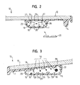
- FIGs 2 and 3 two embodiments of the vehicle roof panel in the form of the lid 10 are explained in more detail.
- the lid 10 is designed to be adjustable and movable. It may be a so-called sliding roof, in which the cover 10 is moved when driving back under the fixed roof, or a so-called spoiler roof, in which the cover 10 is moved over the roof skin.
- An outer skin 12 of the lid 10 is formed by a glass panel or a coextrusion film.
- the coextrusion film consists of plastic or aluminum, is preferably through-dyed and thus replaces an exterior coating.
- the outer skin 12 is that part of the vehicle which is visible from the outside.
- plastic layer 14 produced by foaming, which consists of a PU foam, wherein glass fibers F can be injected by the LFI method in the foam.
- the plastic layer 14 extends bead-like and along the edge of the lid 10 closed as a one-piece frame around the lid 10 or only along the longitudinal edges or transverse edges.
- the surrounding plastic layer 14 is formed in all areas with almost the same thickness to avoid sink marks and to improve the surface quality. There are no ribs or the like outside.
- the plastic body 16 is made of a thermoplastic, in particular of ABS or polypropylene, and reinforced with glass fibers 18. Alternatively, carbon fibers are used.
- the glass fibers 18 extend through the entire plastic body 16 and parallel to the edge of the lid 10 and thus parallel to each other.
- the reinforcing glass fibers 18 are at least 200 mm long and can be combined into different thickness strands or braided (see thicker glass fiber bundles 18 in Fig. 3).
- the glass fiber content is more than 30 wt .-% of the plastic body 16th
- FIG 2 two oval cavities 20 are shown, which pull through the plastic body 16, which is designed as a hollow profile. These cavities 20 reduce the weight of the plastic body 16 and thus the entire lid 10.
- the cavities 20 are closed by end caps 21, which prevent foaming material from penetrating into the cavities 20 during foaming of the plastic layer 14.
- the caps 21 can also engage grooves 26 which are provided on an outer side 22 of the plastic body 16 ( Figure 2).
- the caps 21 go when they are e.g. Detent fingers have, with the grooves 26 a clip connection.
- a signal transmission means 27 (electric cable, traction means and the like) can be performed.
- extensions 28 which are provided either selectively or over the entire length of the plastic body 16 extending.
- the extensions 28 may be trapezoidal or mushroom-shaped in order to produce undercuts 24 which improve the cohesion between the plastic layer 14 and the plastic body 16.
- FIG. 3 otherwise corresponds to the cover 10 shown in FIG. 2, and reference is made to the above explanations.
- the same reference numerals are used for the same components.
- the extensions 28 of the plastic body 16 shown in FIG. 3 extend to the outside of the plastic layer 14 and serve to position the plastic body 16 in a foaming mold.
- the extensions 28 also adjoin the adjacent glass panel and form spacers which keep the distance between the plastic body 16 and the glass panel 14 constant during foaming and curing of the plastic layer 14.
- Recesses 30 in the plastic layer 14 shown in Figure 3 continue in indentations in the plastic body 16 to hold inserts for attachments. These inserts are e.g. Sun visors attached, if it is the vehicle body attachment to a roof module 8.
- the outer skin 12 which is formed by a glass panel or a coextrusion film, is inserted into a foaming tool.
- the made in a separate step of polypropylene and reinforced with glass fibers 18 plastic body 16 is positioned by means of the extensions 28 in the foaming tool.
- Liquid PU material is introduced into the closed mold, wherein optional glass fibers F are injected with (LFI method). The PU material foams, fills out the cavity formed in the foaming tool and adheres to the back of the outer skin.
- plastic bodies are also provided only along the edges to form a reinforcing frame, so that these roof modules, seen in the edge section, look exactly like that shown in the figures Cover.
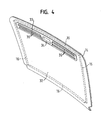
- FIG. 4 shows a vehicle interior trim part in the form of a sliding headliner 32, which can be moved in front of the sunroof cover.
- This comprises an outer skin 12 made of a film or a textile, which is backfoamed all over the back with a fiber-reinforced plastic layer 14 (LFI method).
- LFI method fiber-reinforced plastic layer 14
- the fully reinforced in the plastic layer 14, fiber reinforced plastic body 16 (shown in phantom) form a stiffening frame.
- a fan bar 33 with handle 34 and slots 36 is inserted into the panel.
- a thickened, bead-like portion of the plastic layer 14 extends along the edge. In this thickened portion are also the plastic body 16th
Landscapes
- Engineering & Computer Science (AREA)
- Chemical & Material Sciences (AREA)
- Combustion & Propulsion (AREA)
- Transportation (AREA)
- Mechanical Engineering (AREA)
- Architecture (AREA)
- Structural Engineering (AREA)
- Laminated Bodies (AREA)
- Vehicle Interior And Exterior Ornaments, Soundproofing, And Insulation (AREA)
- Body Structure For Vehicles (AREA)
Priority Applications (2)
| Application Number | Priority Date | Filing Date | Title |
|---|---|---|---|
| EP05023149A EP1775201A3 (fr) | 2005-10-17 | 2005-10-24 | Pièce composite, notamment un panneau de véhicule |
| US11/582,270 US20070087200A1 (en) | 2005-10-17 | 2006-10-17 | Composite vehicle panel |
Applications Claiming Priority (2)
| Application Number | Priority Date | Filing Date | Title |
|---|---|---|---|
| EP05022620 | 2005-10-17 | ||
| EP05023149A EP1775201A3 (fr) | 2005-10-17 | 2005-10-24 | Pièce composite, notamment un panneau de véhicule |
Publications (2)
| Publication Number | Publication Date |
|---|---|
| EP1775201A2 true EP1775201A2 (fr) | 2007-04-18 |
| EP1775201A3 EP1775201A3 (fr) | 2007-05-30 |
Family
ID=35606670
Family Applications (1)
| Application Number | Title | Priority Date | Filing Date |
|---|---|---|---|
| EP05023149A Withdrawn EP1775201A3 (fr) | 2005-10-17 | 2005-10-24 | Pièce composite, notamment un panneau de véhicule |
Country Status (1)
| Country | Link |
|---|---|
| EP (1) | EP1775201A3 (fr) |
Cited By (2)
| Publication number | Priority date | Publication date | Assignee | Title |
|---|---|---|---|---|
| DE102011104374A1 (de) | 2011-06-16 | 2012-12-20 | Daimler Ag | Glasdeckel für ein Kraftfahrzeug-Dach |
| DE102013009107A1 (de) * | 2013-05-29 | 2014-12-04 | Webasto SE | Fahrzeugverstärkungsbauteil an einem Fahrzeugdachbauteil |
Family Cites Families (5)
| Publication number | Priority date | Publication date | Assignee | Title |
|---|---|---|---|---|
| DE19637793C1 (de) * | 1996-09-17 | 1997-11-13 | Webasto Systemkomponenten Gmbh | Deckel für ein Fahrzeugdach |
| US6299246B1 (en) * | 1996-10-08 | 2001-10-09 | Rcc Regional Compact Car Ag | Plastic molded part and construction structure |
| JP2000142461A (ja) * | 1998-11-04 | 2000-05-23 | Japan Automobile Research Inst Inc | ハイブリッド型衝撃吸収用構造部材 |
| DE10308582A1 (de) * | 2003-02-27 | 2004-09-30 | Arvinmeritor Gmbh | Verfahren zum Herstellen eines Fahrzeug-Karosserieteils |
| DE10327839A1 (de) * | 2003-06-20 | 2005-01-05 | Arvinmeritor Gmbh | Fahrzeugdachmodul |
-
2005
- 2005-10-24 EP EP05023149A patent/EP1775201A3/fr not_active Withdrawn
Non-Patent Citations (1)
| Title |
|---|
| None |
Cited By (2)
| Publication number | Priority date | Publication date | Assignee | Title |
|---|---|---|---|---|
| DE102011104374A1 (de) | 2011-06-16 | 2012-12-20 | Daimler Ag | Glasdeckel für ein Kraftfahrzeug-Dach |
| DE102013009107A1 (de) * | 2013-05-29 | 2014-12-04 | Webasto SE | Fahrzeugverstärkungsbauteil an einem Fahrzeugdachbauteil |
Also Published As
| Publication number | Publication date |
|---|---|
| EP1775201A3 (fr) | 2007-05-30 |
Similar Documents
| Publication | Publication Date | Title |
|---|---|---|
| EP1914097B1 (fr) | Cadre pour un toit de véhicule automobile | |
| EP1193163B1 (fr) | Elément composite pour carrosseries de véhicule | |
| EP0853555B1 (fr) | Element de paroi ou element de construction et son procede de fabrication | |
| DE102009035777A1 (de) | Strukturbauteil sowie Verfahren zum Herstellen eines Strukturbauteils | |
| WO2011128081A1 (fr) | Carrosserie de véhicule et procédé de fabrication d'une carrosserie de véhicule | |
| DE102009042272A1 (de) | Leichtbauteil | |
| EP1556240A1 (fr) | Bourrelet d'etancheite pour garnitures d'etancheite de carrosserie, presentant un profil d'etancheite partiellement renforce | |
| EP2895381B1 (fr) | Carrosserie de véhicule automobile comprenant une paroi latérale et son procédé de fabrication | |
| EP1488985B1 (fr) | Module de toit de véhicule | |
| DE3035644A1 (de) | Boden fuer ein fahrzeug, insbesondere kraftfahrzeug | |
| EP1612024A1 (fr) | Procédé pour la fabrication d'un composant renforcé et composant renforcé | |
| DE102019132793A1 (de) | Hybrid-türmodul | |
| EP1494882B1 (fr) | Portiere de vehicule et procede permettant de la produire | |
| EP1637439B1 (fr) | Elément de carrosserie, en particulier panneau de toit de véhicule | |
| DE102004044159A1 (de) | Verbundbauteil, insbesondere Karosserieanbauteil für ein Fahrzeug, und Verfahren zum Herstellen eines solchen Verbundbauteils | |
| EP1669277B1 (fr) | Accessoire de carrosserie véhicule, produit intermédiaire, et son procédé de fabrication | |
| EP1775201A2 (fr) | Pièce composite, notamment un panneau de véhicule | |
| DE102015012262B4 (de) | Tür für einen Kraftwagen | |
| DE10202911C1 (de) | Verbundbauteil für eine Fahrzeugkarosserie, insbesondere für ein Fahrzeugdach | |
| EP1219483B1 (fr) | Encadrement pour une porte de véhicule | |
| DE202006005797U1 (de) | Türmodulträger für eine Kraftfahrzeugtür | |
| WO2014191158A2 (fr) | Élément de renforcement de véhicule agencé sur un élément de toit de véhicule | |
| DE102018211963A1 (de) | Fahrzeugtür und Fahrzeug mit zumindest einer Fahrzeugtür | |
| WO2012167879A2 (fr) | Composant de véhicule | |
| EP0630775A1 (fr) | Porte de véhicule |
Legal Events
| Date | Code | Title | Description |
|---|---|---|---|
| PUAI | Public reference made under article 153(3) epc to a published international application that has entered the european phase |
Free format text: ORIGINAL CODE: 0009012 |
|
| AK | Designated contracting states |
Kind code of ref document: A2 Designated state(s): AT BE BG CH CY CZ DE DK EE ES FI FR GB GR HU IE IS IT LI LT LU LV MC NL PL PT RO SE SI SK TR |
|
| AX | Request for extension of the european patent |
Extension state: AL BA HR MK YU |
|
| PUAL | Search report despatched |
Free format text: ORIGINAL CODE: 0009013 |
|
| AK | Designated contracting states |
Kind code of ref document: A3 Designated state(s): AT BE BG CH CY CZ DE DK EE ES FI FR GB GR HU IE IS IT LI LT LU LV MC NL PL PT RO SE SI SK TR |
|
| AX | Request for extension of the european patent |
Extension state: AL BA HR MK YU |
|
| AKX | Designation fees paid | ||
| STAA | Information on the status of an ep patent application or granted ep patent |
Free format text: STATUS: THE APPLICATION IS DEEMED TO BE WITHDRAWN |
|
| 18D | Application deemed to be withdrawn |
Effective date: 20071201 |
|
| REG | Reference to a national code |
Ref country code: DE Ref legal event code: 8566 |