EP1775217B1 - Dispositif de fixation d'un siège - Google Patents
Dispositif de fixation d'un siège Download PDFInfo
- Publication number
- EP1775217B1 EP1775217B1 EP06015643A EP06015643A EP1775217B1 EP 1775217 B1 EP1775217 B1 EP 1775217B1 EP 06015643 A EP06015643 A EP 06015643A EP 06015643 A EP06015643 A EP 06015643A EP 1775217 B1 EP1775217 B1 EP 1775217B1
- Authority
- EP
- European Patent Office
- Prior art keywords
- seat
- fastening device
- horizontal
- movement
- longitudinal direction
- Prior art date
- Legal status (The legal status is an assumption and is not a legal conclusion. Google has not performed a legal analysis and makes no representation as to the accuracy of the status listed.)
- Not-in-force
Links
- 230000005540 biological transmission Effects 0.000 claims description 10
- 238000006243 chemical reaction Methods 0.000 claims 1
- 239000000523 sample Substances 0.000 claims 1
- 238000010276 construction Methods 0.000 description 3
- 238000006073 displacement reaction Methods 0.000 description 3
- 238000007373 indentation Methods 0.000 description 2
- 238000009434 installation Methods 0.000 description 2
- 239000000463 material Substances 0.000 description 2
- 230000000284 resting effect Effects 0.000 description 2
- 229910000639 Spring steel Inorganic materials 0.000 description 1
- 238000005452 bending Methods 0.000 description 1
- 230000015572 biosynthetic process Effects 0.000 description 1
- 238000005755 formation reaction Methods 0.000 description 1
Images



Classifications
-
- B—PERFORMING OPERATIONS; TRANSPORTING
- B64—AIRCRAFT; AVIATION; COSMONAUTICS
- B64D—EQUIPMENT FOR FITTING IN OR TO AIRCRAFT; FLIGHT SUITS; PARACHUTES; ARRANGEMENT OR MOUNTING OF POWER PLANTS OR PROPULSION TRANSMISSIONS IN AIRCRAFT
- B64D11/00—Passenger or crew accommodation; Flight-deck installations not otherwise provided for
- B64D11/06—Arrangements of seats, or adaptations or details specially adapted for aircraft seats
- B64D11/0696—Means for fastening seats to floors, e.g. to floor rails
Definitions
- the invention relates to a seat attachment device according to the preamble of claim 1.
- a seat attachment device for securing a seat to a floor of an aircraft.
- the seat attachment device has horizontal attachment means and vertical attachment means.
- the vertical attachment means are displaceable in a horizontal longitudinal direction, parallel to a mounting rail, relative to the horizontal attachment means.
- the seat mounting device comprises a rotatably mounted actuating means and a gear unit for transmitting a rotary movement of the actuating means in a sliding movement of the vertical fastening means in the horizontal longitudinal direction.
- the actuating means is formed by a horizontal, parallel to the horizontal longitudinal direction aligned rod having a matching with its longitudinal axis of rotation axis. To the actuating means, a part of the gear unit forming thread is formed, engage in the coupled with the vertical attachment means pins.
- a generic seat mounting device with an actuating means which is rotatably mounted about a vertical axis. This also has a gear unit for transmitting a rotational movement of the actuating means in a sliding movement of a vertical attachment means in the horizontal longitudinal direction, which is intended to transmit the rotational movement of the actuating means in a clamping movement.
- the invention is in particular the object of providing a seat mounting device that allows a compact design. It is achieved according to the invention by the features of claim 1. Further embodiments emerge from the subclaims.
- the invention relates to a seat mounting device, in particular for fastening a seat to a floor of an aircraft, with at least one horizontal attachment means and at least one vertical attachment means which is displaceable in a horizontal longitudinal direction relative to the horizontal attachment means, and with a rotatable actuating means and a transmission unit for transmitting a rotational movement the actuating means in a sliding movement of the vertical fastening means in the horizontal longitudinal direction, wherein the actuating means at least one axis of rotation having an angle greater than 20 ° to the horizontal longitudinal direction, and the gear unit is provided to transmit the rotational movement of the actuating means in a clamping movement.
- the gear unit has a cam gear unit to transmit the rotational movement in the clamping movement. It should be under a "HorizoritallNicolsraum" in particular at least substantially parallel to a mounted floor support plane of the seat mounting device or - in an installation position - a to a main floor level of a floor on which a seat is to be elevated, extending Direction are understood, which is also aligned in the longitudinal direction of the seat attachment device - and thus in particular in or against a seat direction of a seat to be mounted - and in the longitudinal direction of a mounted on the floor mounting rail.
- a "HorizoritallNicolsraum" in particular at least substantially parallel to a mounted floor support plane of the seat mounting device or - in an installation position - a to a main floor level of a floor on which a seat is to be elevated, extending Direction are understood, which is also aligned in the longitudinal direction of the seat attachment device - and thus in particular in or against a seat direction of a seat to be mounted - and in the longitudinal
- vertical should be understood to mean, in particular, standing vertically at least on a floor support plane spanned by the seat fastening device or standing on the main floor level of the floor on which a seat is to be raised. It should be understood by a “clamping movement” both a movement to reduce and in particular cancellation of a clamping force and a movement to generate or increase a clamping force.
- a “cam mechanism unit” should be understood to mean, in particular, a unit which has a cam member forming a cam track and a scanning member provided with the cam track for correspondence.
- a particularly compact and structurally simple construction can be achieved, in particular by the actuating means can be made very short and compact. Due to the cam gear unit, the rotational movement can be transmitted structurally simple and with a compact design. Furthermore, a comfortable operability can be achieved, in particular if the axis of rotation to a horizontal plane of the seat mounting device includes an angle greater than 20 ° and / or the axis of rotation of the actuating means forms an angle greater than 45 ° and more preferably greater than 60 ° to the horizontal direction and / or particularly preferably to the horizontal plane.
- a "horizontal plane” is to be understood in particular as meaning a plane running parallel to a ground support plane spanned by the seat fastening device.
- the rotational movement of the actuating means can be transmitted by various, the skilled person appear appropriate gear in the sliding movement of the vertical attachment means, such as a thread, a rack, a gear, etc.
- gear unit on an eccentric which is used to transmit the rotational movement of the actuating means in the displacement movement of the vertical fastening means is provided, the corresponding transmission can be realized particularly simple in construction with a compact construction.
- the cam gear unit may have a rigid or immovably mounted scanning member, so that a component having the cam track is driven by the RelaLivterrorism between the scanning member and the cam member in a desired direction, or the cam gear unit may have a movably mounted scanning member, whereby the design effort can be reduced.
- the actuating means in addition to a rotatable mounting must be mounted translationally displaceable.
- eccentric and the cam gear unit are at least partially formed in one piece, additional components, space, weight, assembly costs and costs can be saved.
- the seat fastening device has at least one spring element formed separately from the vertical fastening means, which is provided for the elastic deflection by the clamping movement.
- the spring element and the vertical attachment means can be made at least of different materials, so that in particular the materials can be advantageously adapted to the functions.
- the spring element is band-shaped, i. has the same compared to its length and width on a relatively small thickness, the spring element can be integrated to save space and advantageously be used for other functions. If the spring element is provided as a cover element, additional cover elements can be avoided and a relatively large spring element can be achieved without at least substantial installation space disadvantages, by means of which an advantageously large spring travel can be realized.
- the seat fastening device has a locking display unit and / or the seat fastening device has a rotation locking unit provided for securing the actuating means in at least one rotational position, an increased operating safety can be achieved.
- the locking display unit and the spring element, the anti-rotation unit and the spring element and / or the anti-rotation unit and the eccentric are at least partially integral, again additional components, space, weight, assembly costs and costs can be saved.
- a seat attachment device is particularly advantageous for attaching an aircraft seat in an aircraft, but is also used in other, the expert appears reasonable areas, such as in the field of vehicles, such as larger passenger cars, coaches, ship ferries, or in the context of a room seating, as for a conference hall, a theater, a cinema hall, etc. Further, the seat attachment device can be Also for lashing loads, luggage or other cargo of aircraft and vehicles use of any kind.
- FIG. 1 shows a seat attachment device for attaching a seat to a floor 28a or a cabin floor of an aircraft, namely on extending in the longitudinal direction of the aircraft, fixed to the cabin floor and aligned parallel to the same mounting rails 42a.
- the fastening rails 42a are flush with their upper side flush with the floor 28a or cabin floor of the aircraft.
- the fastening rail 42a is formed by a hollow profile which, on its upper side with mutually facing profile flanks 46a, delimits a longitudinal channel 44a.
- the longitudinal channel 44a has in a predetermined measure its free inlet cross-section widening passage openings 48a, which have a uniform spacing from each other and are designed like a hole.
- the seat attachment device has a base body 40a with an integrally formed bearing eye 50a for fastening a seat foot 52a. Furthermore, horizontal attachment means 10a, 12a are integrally formed on the base body 40a, ( FIGS. 1 and 2 ).
- the horizontal attachment means 10a, 12a extend in the vertical direction 62a beyond a bearing surface 78a of the main body 40a, by means of which the base body 40a comes to rest on a top side of the mounting rail 42a during assembly, and wherein the support surface 78a defines a plane defined as a horizontal plane 30a
- Seat attachment device spans which is viewed in the installed position at least substantially aligned parallel to the bottom 28a. Furthermore, the horizontal attachment means 10a, 12a have transverse to the longitudinal extension of the main body 40a on both sides projecting circular segment-shaped formations.
- the seat fastening device has a relative to the base body 40a in the horizontal longitudinal direction 56a, 58a sliding sliding part 54a, are longitudinally integrally formed in the longitudinal direction of the seat attachment device or in the horizontal direction 56a, 58a to the horizontal fastening means 10a, 12a spaced vertical fastening means 14a, 16a, 18a.
- the horizontal longitudinal direction 56a, 58a extends at least substantially parallel to the longitudinal direction of the sliding part 54a and viewed in the installed position at least substantially parallel to the mounting rail 42a and thus at least substantially parallel to the bottom 28a.
- the vertical fastening means 14a, 16a, 18a project beyond the horizontal fastening means 10a, 12a in the vertical direction 62a facing away from a cover side of the seat fastening device and have circular-segment-shaped protrusions projecting on both sides transversely to the longitudinal extent of the sliding part 54a.
- the seat mounting device has a in a recess of the base body 40a rotatably mounted and guided by the base body 40a in its rotational movement actuating means 20a and a transmission unit 22a for transmission a rotational movement of the actuating means 20a in a sliding movement of the sliding part 54a with the vertical fastening means 14a, 16a, 18a in the horizontal direction 56a, 58a.
- the actuating means 20a has a rotation axis 24a which encloses an angle 26a of approximately 90 ° to the horizontal longitudinal direction 56a, 58a and an angle 32a of approximately 90 ° to the horizontal plane 30a of the seat attachment device or the rotation axis 24a is at least substantially perpendicular to the horizontal plane 30a of the seat attachment device and viewed in the installed position at least substantially aligned perpendicular to the bottom 28a.
- the gear unit 22a has an eccentric 34a formed partially integrally with the actuating means 20a, which is provided for transmitting the rotational movement of the actuating means 20a into the displacement movement in the horizontal longitudinal direction 56a, 58a of the sliding part 54a with the vertical fastening means 14a, 16a, 18a.
- the eccentric 34a in this case has an eccentric pin 64a, which is on a bottom of the actuating means 20a in the same radially to the rotation axis 24a spaced or eccentrically screwed.
- the eccentric pin 64a engages in a curved slot 66a of the sliding part 54a, which is aligned transversely to the longitudinal extension of the sliding part 54a or transversely to the horizontal longitudinal direction 56a, 58a ( FIG. 4 ).
- the gear unit 22a is provided to transmit the rotational movement of the actuating means 20a in a clamping movement.
- the gear unit 22a has a cam mechanism unit formed with a integrally formed on the actuating means 20a, formed by a groove cam member 68a and on both sides in the base body 40a, formed by pins scanning members 70a, which engage in the cam member 68a forming groove and of which only one is shown.
- the scanning members 70a are arranged vertically offset in the vertical direction 60a and 62a in the base body 40a, so that a particularly short-built actuating means 20a and an advantageous scanning can be achieved.
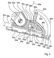
- the seat mounting device has a band-shaped, in a side view substantially V-shaped spring element 36a made of a spring steel sheet separately formed by the sliding part 54a and by the vertical fastening means 14a, 16a, 18a, which is provided for the elastic deflection by the clamping movement.
- the spring element 36a is clamped with a free end via a screw not shown in the sliding part 54a has, after its chucking an angling about 130 ° and extending from its angled portion in the direction of the actuating means 20a.
- the spring element 36a serves as a cover element and forms a cover side of the seat attachment device.
- the seat attachment device has a lock display unit 38a and a rotational locking unit provided for securing the actuating means 20a in a rotational position associated with a locking position, both of which are partially made in one piece with the spring element 36a.
- the locking display unit 38a is essentially formed by a colored area 72a arranged on the base body 40a and a recess 74a of the spring element 36a which comes to rest above the area 72a when the seat fastening device is locked so that the colored area 72a can be seen through the recess 74a of the spring element 36a is ( FIGS. 1 and 2 ).
- the anti-rotation unit is essentially formed by a shape of the cam member 68a molded onto the actuating means 20a or by a recess 76a, by the scanning member 70a and by the spring element 36a, which loads the actuating means 20a in a locking position in the direction of the scanning member 70a, so that the scanning member 70a is spring-loaded in the indentation 76a and undesired release of the actuating means 20a from a locking position is reliably avoided ( FIG. 2 ).
- the horizontal attachment means 10a, 12a engage positively in the passage openings 48a in the horizontal longitudinal direction 56a, 58a, so that the seat attachment device is fixed in a form-fitting manner via the horizontal attachment means 10a, 12a in the horizontal longitudinal direction 56a, 58a.
- the vertical attachment means 14a, 16a, 18a are passed through the passage openings 48a and the base body 40a comes with its support surface 78a, which runs parallel to the plane defined as horizontal plane 30a of the seat attachment device, on the upper side of the mounting rail 42a ( FIG. 3 ).
- the actuating means 20a has on its cover side or on the vertical fastening means 14a, 16a, 18a side facing away from a hexagon socket over which the actuating means 20a are then rotated by a hexagon wrench 80a by approximately 210 ° counterclockwise from its unlocked position into its locking position can Figures 3 and 2 ).
- the slot 66a describes in its end to the edge of the sliding part 54a towards an outwardly forced circular path, so that by means of a rotation of 210 °, a desired longitudinal displacement is achieved ( FIG. 4 ).
- end stops formed by the cam member 68a it is ensured that the actuating means 20a can be rotated by a maximum of 210 °.
- the spring element 36a has at its end facing the actuating means 20a a recess 82a through which the hexagonal wrench 80a can be guided for actuating the actuating means 20a.
- the spring element 36a terminates flush with a cover side of the main body 40a and comes with its recess 74a above the color-coded area 72a to lie.
- a built-up by the deflection of the spring element 36a clamping force is transmitted from the spring element 36a on the sliding part 54a, so that this is moved together with the vertical attachment means 14a, 16a, 18a in the vertical direction 60a to the base body 40a and the vertical attachment means 14a, 16a, 18a with a clamping force on an underside of the profile edges 46a create the same.
- the seat attachment device is thus positively and non-positively fixed in the horizontal longitudinal direction 56a, 58a and in the vertical direction 60a, 62a. Due to the frictional connection, in particular relative movements of the seat fastening device to the fastening rail 42a and a consequent noise development can be avoided.
- An unlocking of the seat mounting device is carried out accordingly in reverse order to lock.
- FIGS. 5 and 6 show a seat attachment device with an actuating means 20b, which has instead of a groove formed by a cam member 68a on a cover side, formed by a cam contour curve member 68b.
- cam member 68b acts a pivotally mounted, formed by a bending plate sensing member 70b together, which has at its free end an angled portion which rests with its end face on the cam contour. If the actuating means 20b is rotated according to the embodiment in the FIGS. 1 to 4 a sliding part 54b displaced in the horizontal direction 58b by means of an eccentric 34b ( FIGS. 6 and 5 ).
- the scanning member 70b driven by the cam gear unit, pivoted in the vertical direction 60b, whereby a resting on an upper surface of the Abtastglieds 70b spring element 36b is deflected and tensioned without the actuating means 20b in its entirety a lifting movement in vertical direction 60b performs.
Landscapes
- Engineering & Computer Science (AREA)
- Aviation & Aerospace Engineering (AREA)
- Seats For Vehicles (AREA)
- Chairs For Special Purposes, Such As Reclining Chairs (AREA)
- Clamps And Clips (AREA)
- Massaging Devices (AREA)
Claims (13)
- Dispositif de fixation d'un siège, en particulier pour la fixation d'un siège à un plancher (28) d'un avion, avec au moins un moyen de fixation horizontal (10, 12) et au moins un moyen de fixation vertical (14, 16, 18), qui peut se déplacer dans une direction longitudinale horizontale (56, 58) par rapport au moyen de fixation horizontal (10, 12), et avec un moyen d'actionnement rotatif (20) ainsi qu'une unité de commande (22) pour la transmission d'un mouvement de rotation du moyen d'actionnement (20) dans une direction de déplacement du moyen de fixation vertical (14, 16, 18) dans la direction longitudinale horizontale (56, 58), dans lequel le moyen d'actionnement (20) présente au moins un axe de rotation (24), qui forme un angle (26) supérieur à 20° avec la direction longitudinale horizontale (56, 58), et l'unité de commande (22) est prévue pour transmettre le mouvement de rotation du moyen d'actionnement (20) dans un mouvement de serrage, caractérisé en ce que l'unité de commande (22) comprend une unité de commande à cames, pour transmettre le mouvement de rotation dans le mouvement de serrage.
- Dispositif de fixation d'un siège selon la revendication 1, caractérisé en ce que l'axe de rotation (24) du moyen d'actionnement (20) forme un angle (32) de plus de 20° avec un plan horizontal (30).
- Dispositif de fixation d'un siège selon l'une quelconque des revendications précédentes, caractérisé en ce que l'unité de commande (22) comprend un excentrique (34), qui est prévu pour la transmission du mouvement de rotation du moyen d'actionnement (20) dans le mouvement de déplacement du moyen de fixation vertical (14, 16, 18) dans la direction longitudinale horizontale (56, 58).
- Dispositif de fixation d'un siège selon l'une quelconque des revendications précédentes, caractérisé en ce que l'unité de commande à cames de l'unité de commande (22b) comprend un organe palpeur (70b) monté de façon mobile.
- Dispositif de fixation d'un siège selon la revendication 3, caractérisé en ce que l'excentrique (34) et l'unité de commande à cames sont réalisés au moins partiellement en une seule pièce.
- Dispositif de fixation d'un siège selon l'une quelconque des revendications précédentes, caractérisé par au moins un élément de ressort (36) réalisé séparément du moyen de fixation vertical (14, 16, 18), et qui est prévu pour une élongation élastique par le mouvement de serrage.
- Dispositif de fixation d'un siège selon la revendication 6, caractérisé en ce que l'élément de ressort (36) est réalisé en forme de bande.
- Dispositif de fixation d'un siège selon la revendication 6, caractérisé en ce que l'élément de ressort (36) est prévu en forme d'élément de masquage.
- Dispositif de fixation d'un siège selon l'une quelconque des revendications précédentes, caractérisé par une unité d'affichage de verrouillage (38a).
- Dispositif de fixation d'un siège selon la revendications 6 et 9, caractérisé en ce que l'unité d'affichage de verrouillage (38a) et l'élément de ressort (36a) sont réalisés au moins partiellement en une seule pièce.
- Dispositif de fixation d'un siège selon l'une quelconque des revendications précédentes, caractérisé par une unité de blocage de rotation, qui est prévue pour le blocage du moyen d'actionnement (20a) dans au moins une position angulaire.
- Dispositif de fixation d'un siège selon la revendication 6 et 11, caractérisé en ce que l'unité de blocage de rotation et l'élément de ressort (36a) sont réalisés au moins partiellement en une seule pièce.
- Dispositif de fixation d'un siège selon la revendication 3 et 11, caractérisé en ce que l'unité de blocage de rotation et l'excentrique (34a) sont réalisés au moins partiellement en une seule pièce.
Applications Claiming Priority (1)
| Application Number | Priority Date | Filing Date | Title |
|---|---|---|---|
| DE102005049187A DE102005049187A1 (de) | 2005-10-14 | 2005-10-14 | Sitzbefestigungsvorrichtung |
Publications (3)
| Publication Number | Publication Date |
|---|---|
| EP1775217A2 EP1775217A2 (fr) | 2007-04-18 |
| EP1775217A3 EP1775217A3 (fr) | 2008-02-27 |
| EP1775217B1 true EP1775217B1 (fr) | 2010-01-13 |
Family
ID=37591855
Family Applications (1)
| Application Number | Title | Priority Date | Filing Date |
|---|---|---|---|
| EP06015643A Not-in-force EP1775217B1 (fr) | 2005-10-14 | 2006-07-27 | Dispositif de fixation d'un siège |
Country Status (4)
| Country | Link |
|---|---|
| US (1) | US7661637B2 (fr) |
| EP (1) | EP1775217B1 (fr) |
| AT (1) | ATE455037T1 (fr) |
| DE (2) | DE102005049187A1 (fr) |
Cited By (1)
| Publication number | Priority date | Publication date | Assignee | Title |
|---|---|---|---|---|
| DE102013000728A1 (de) | 2013-01-17 | 2014-03-13 | Daimler Ag | Vorrichtung zur lösbaren Befestigung von Einbauteilen |
Families Citing this family (34)
| Publication number | Priority date | Publication date | Assignee | Title |
|---|---|---|---|---|
| DE102008048745B4 (de) * | 2008-09-24 | 2014-01-02 | Airbus Operations Gmbh | Arretiervorrichtung für ein an einer Schiene arretierbares Objekt, Verwendung einer derartigen Arretiervorrichtung und Verkehrsmittel mit einer derartigen Vorrichtung |
| DE102008062466A1 (de) * | 2008-12-17 | 2010-08-26 | Airbus Deutschland Gmbh | Vorrichtung zum Befestigen eines Objekts an einer Schiene |
| DE102009014722B4 (de) * | 2009-03-27 | 2016-06-23 | Recaro Aircraft Seating Gmbh & Co. Kg | Sitzbefestigungsvorrichtung |
| FR2947773B1 (fr) * | 2009-07-09 | 2012-01-06 | Attax | Systeme de fixation d'un siege par exemple d'aeronef |
| FR2957330B1 (fr) | 2010-03-12 | 2012-04-20 | Attax | Systeme d'accrochage d'un siege d'aeronef |
| FR2959985B1 (fr) * | 2010-05-17 | 2013-02-22 | Attax | Systeme d'accrochage d'un siege d'aeronef dans un rail de fixation |
| DE102012205467A1 (de) * | 2012-04-03 | 2013-10-10 | Airbus Operations Gmbh | Vorrichtung sowie Verfahren zur Montage einer Klemmeinrichtung in einer Profilschiene |
| DE102013103435A1 (de) | 2013-04-05 | 2014-10-09 | Recaro Aircraft Seating Gmbh & Co. Kg | Sitzbefestigung |
| DE102014201176A1 (de) * | 2014-01-23 | 2015-07-23 | Bishop Gmbh | Flugzeugsitzbeschlag |
| DE102016110057A1 (de) * | 2016-05-31 | 2017-11-30 | Airbus Operations Gmbh | Passagiersitzsystem für eine Kabine eines Transportmittels |
| US11358497B2 (en) | 2018-05-04 | 2022-06-14 | Lear Corporation | Track system having a rolling member |
| US10882420B2 (en) | 2019-03-08 | 2021-01-05 | Lear Corporation | Track assembly |
| US10889208B2 (en) | 2018-05-04 | 2021-01-12 | Lear Corporation | Track assembly |
| US11040638B2 (en) | 2018-05-04 | 2021-06-22 | Lear Corporation | Track assembly |
| US10926667B2 (en) | 2018-05-04 | 2021-02-23 | Lear Corporation | Track assembly |
| US11506272B2 (en) | 2020-02-21 | 2022-11-22 | Lear Corporation | Track system with a support member |
| US12233756B2 (en) | 2018-05-04 | 2025-02-25 | Lear Corporation | Track system with a support member |
| US11040639B2 (en) | 2018-05-04 | 2021-06-22 | Lear Corporation | Track assembly |
| US10906431B2 (en) | 2018-05-04 | 2021-02-02 | Lear Corporation | Track assembly |
| US11225201B2 (en) | 2018-12-10 | 2022-01-18 | Lear Corporation | Track assembly |
| US11440482B2 (en) | 2018-12-10 | 2022-09-13 | Lear Corporation | Track assembly |
| US11117538B2 (en) | 2018-12-17 | 2021-09-14 | Lear Corporation | Electrical assembly |
| US10855037B2 (en) | 2018-12-17 | 2020-12-01 | Lear Corporation | Support assembly with a support member and a track assembly |
| US11613220B2 (en) | 2018-12-17 | 2023-03-28 | Lear Corporation | Electrical assembly |
| US10950977B2 (en) | 2018-12-18 | 2021-03-16 | Lear Corporation | Track assembly for a vehicle component |
| US11975665B2 (en) | 2019-02-20 | 2024-05-07 | Lear Corporation | Electrical assembly |
| US11040653B2 (en) | 2019-02-25 | 2021-06-22 | Lear Corporation | Track assembly |
| US11807142B2 (en) | 2019-03-06 | 2023-11-07 | Lear Corporation | Electrical track assembly |
| US11299075B2 (en) | 2019-03-06 | 2022-04-12 | Lear Corporation | Electrical assembly |
| US11463083B2 (en) | 2019-10-04 | 2022-10-04 | Lear Corporation | Electrical system |
| US11323114B2 (en) | 2019-10-04 | 2022-05-03 | Lear Corporation | Electrical system |
| US11634101B2 (en) | 2019-10-04 | 2023-04-25 | Lear Corporation | Removable component system |
| DE102021104018B4 (de) | 2020-02-21 | 2023-11-09 | Lear Corporation | Schienensystem mit einem Stützelement, Verfahren zum Betreiben eines Schienensystems |
| US11505141B2 (en) | 2020-10-23 | 2022-11-22 | Lear Corporation | Electrical system with track assembly and support assembly |
Family Cites Families (17)
| Publication number | Priority date | Publication date | Assignee | Title |
|---|---|---|---|---|
| DE2552761A1 (de) * | 1975-11-25 | 1977-05-26 | Keiper Kg | Laengsverschiebbarer und in auswaehlbaren laengslagen feststellbarer, insbesondere in fahrzeugen wie kraftwagen anzuordnender sitz |
| US4047689A (en) * | 1976-07-19 | 1977-09-13 | Uop Inc. | Load distributing track fitting |
| US4062298A (en) * | 1976-11-10 | 1977-12-13 | Uop Inc. | Anti rattle track fitting |
| US4376522A (en) * | 1981-05-18 | 1983-03-15 | Kidde, Inc. | Aircraft seat |
| US4496271A (en) * | 1982-09-30 | 1985-01-29 | East/West Industries, Inc. | Restraining fittings |
| US4708549A (en) * | 1986-05-01 | 1987-11-24 | Ancra Corporation | Rattle-proof anchor fitting for securing loads to retainer track |
| US4796837A (en) * | 1987-07-27 | 1989-01-10 | Dowd Eugene G | Leg seat track fitting with improved bearing member |
| US4771969A (en) * | 1987-07-27 | 1988-09-20 | Sabre Industries, Inc. | Leg set track fitting |
| US5083726A (en) * | 1989-05-10 | 1992-01-28 | Sabre Industries, Inc. | Seat track bearing for an airplane |
| GB9013717D0 (en) | 1990-06-20 | 1990-08-08 | Rumbold Ltd L A | Adjustable passenger seating arrangement |
| DE59200813D1 (de) * | 1991-04-27 | 1995-01-05 | Michler Walter Dipl Ing Fh | Schnell-befestigungsvorrichtung. |
| DE19520959C2 (de) * | 1995-06-08 | 2000-08-17 | Albert Muehlenberg Apparatebau | Schnellwechselbeschlag |
| US5871318A (en) * | 1997-11-12 | 1999-02-16 | Be Aerospace, Inc. | Quick-release track fastener |
| DE19937652A1 (de) * | 1999-08-12 | 2001-02-15 | Hammerstein Gmbh C Rob | Betätigungsvorrichtung für eine Arretierung eines Fahrzeugsitzes |
| DE10341624A1 (de) * | 2003-09-10 | 2005-04-07 | Recaro Aircraft Seating Gmbh & Co. Kg | Sitzbefestigungssystem |
| GB0323866D0 (en) | 2003-10-11 | 2003-11-12 | Unwin C N Ltd | Furniture anchorages |
| US6902365B1 (en) * | 2004-02-13 | 2005-06-07 | B E Aerospace, Inc. | Quick-release track fastener |
-
2005
- 2005-10-14 DE DE102005049187A patent/DE102005049187A1/de not_active Withdrawn
- 2005-12-06 US US11/294,340 patent/US7661637B2/en not_active Expired - Fee Related
-
2006
- 2006-07-27 DE DE502006005898T patent/DE502006005898D1/de active Active
- 2006-07-27 EP EP06015643A patent/EP1775217B1/fr not_active Not-in-force
- 2006-07-27 AT AT06015643T patent/ATE455037T1/de active
Cited By (1)
| Publication number | Priority date | Publication date | Assignee | Title |
|---|---|---|---|---|
| DE102013000728A1 (de) | 2013-01-17 | 2014-03-13 | Daimler Ag | Vorrichtung zur lösbaren Befestigung von Einbauteilen |
Also Published As
| Publication number | Publication date |
|---|---|
| DE102005049187A1 (de) | 2007-04-19 |
| EP1775217A3 (fr) | 2008-02-27 |
| US7661637B2 (en) | 2010-02-16 |
| US20070090261A1 (en) | 2007-04-26 |
| ATE455037T1 (de) | 2010-01-15 |
| DE502006005898D1 (de) | 2010-03-04 |
| EP1775217A2 (fr) | 2007-04-18 |
Similar Documents
| Publication | Publication Date | Title |
|---|---|---|
| EP1775217B1 (fr) | Dispositif de fixation d'un siège | |
| DE19753538B4 (de) | Vorrichtung zum lösbaren Befestigen von Sitzen, Sitzbänken oder anderen Gegenständen am Boden eines Kraftfahrzeuges | |
| DE60315734T2 (de) | Auf der bodenplatte eines fahrzeugs angebrachter verbesserter fussboden zur befestigung von stühlen, sesseln und rollstühlen | |
| EP1792827B1 (fr) | Dispositif de fixation d'un siège | |
| EP1794052B1 (fr) | Dispositif de fixation d'un siege | |
| EP2686212B1 (fr) | Dispositif de réglage en hauteur pour une ferrure de fixation d'un système de ceinture de sécurité | |
| EP2142428B1 (fr) | Dispositif servant a fixer des objets | |
| DE19654395C1 (de) | Nocken zur lösbaren Verriegelung eines Bauteils, insbesondere an einem Kraftfahrzeugsitz | |
| EP0583295A1 (fr) | Dispositif de fixation rapide. | |
| EP2632796B1 (fr) | Dispositif de fixation de siège | |
| EP1180452A2 (fr) | Dispositif de fixation de valises rigides dans le compartiment à bagage d'un véhicule | |
| EP1663780A1 (fr) | Systeme de fixation de siege | |
| EP2981468B1 (fr) | Support de siège | |
| DE19812490A1 (de) | Einrichtung zur lösbaren Befestigung eines Sitzes, insbesondere Fahrzeugsitzes, an einer längsverlaufenden Schiene | |
| EP1336530A2 (fr) | Dispositif de fixation pour siège enfant | |
| DE102021214144B4 (de) | Vorspannelement für ein Schienenpaar einer Sitzlängsverstelleinrichtung und Sitzlängsverstelleinrichtung | |
| DE19927532C2 (de) | Mechanismus zum Anbringen eines Sicherheitsgurtes eines mittleren Sitzplatzes von einem Fahrzeugsitz | |
| DE10255446B4 (de) | Schutzmatte | |
| EP1162112A1 (fr) | Attache pour la fixation d'une charge à une plaque de porteur | |
| DE102013107083B4 (de) | Vorrichtung zum Festlegen eines Gegenstandes | |
| DE3029127A1 (de) | Geradlinig fuehrende verstellschiene | |
| EP1264744A2 (fr) | Dispositif de fixation pour ceinture de sécurité | |
| DE102010031202B4 (de) | Sitzuntergestell für ein Kraftfahrzeug | |
| DE102005050743A1 (de) | Gurtanordnung, insbesondere Sicherheitsgurtanordnung für ein Fahrzeug | |
| EP1313929A1 (fr) | Fixation de porte |
Legal Events
| Date | Code | Title | Description |
|---|---|---|---|
| PUAI | Public reference made under article 153(3) epc to a published international application that has entered the european phase |
Free format text: ORIGINAL CODE: 0009012 |
|
| AK | Designated contracting states |
Kind code of ref document: A2 Designated state(s): AT BE BG CH CY CZ DE DK EE ES FI FR GB GR HU IE IS IT LI LT LU LV MC NL PL PT RO SE SI SK TR |
|
| AX | Request for extension of the european patent |
Extension state: AL BA HR MK YU |
|
| PUAL | Search report despatched |
Free format text: ORIGINAL CODE: 0009013 |
|
| AK | Designated contracting states |
Kind code of ref document: A3 Designated state(s): AT BE BG CH CY CZ DE DK EE ES FI FR GB GR HU IE IS IT LI LT LU LV MC NL PL PT RO SE SI SK TR |
|
| AX | Request for extension of the european patent |
Extension state: AL BA HR MK YU |
|
| 17P | Request for examination filed |
Effective date: 20080429 |
|
| 17Q | First examination report despatched |
Effective date: 20080529 |
|
| AKX | Designation fees paid |
Designated state(s): AT BE BG CH CY CZ DE DK EE ES FI FR GB GR HU IE IS IT LI LT LU LV MC NL PL PT RO SE SI SK TR |
|
| GRAP | Despatch of communication of intention to grant a patent |
Free format text: ORIGINAL CODE: EPIDOSNIGR1 |
|
| GRAS | Grant fee paid |
Free format text: ORIGINAL CODE: EPIDOSNIGR3 |
|
| GRAA | (expected) grant |
Free format text: ORIGINAL CODE: 0009210 |
|
| AK | Designated contracting states |
Kind code of ref document: B1 Designated state(s): AT BE BG CH CY CZ DE DK EE ES FI FR GB GR HU IE IS IT LI LT LU LV MC NL PL PT RO SE SI SK TR |
|
| REG | Reference to a national code |
Ref country code: GB Ref legal event code: FG4D Free format text: NOT ENGLISH |
|
| REG | Reference to a national code |
Ref country code: CH Ref legal event code: EP |
|
| REG | Reference to a national code |
Ref country code: IE Ref legal event code: FG4D |
|
| REF | Corresponds to: |
Ref document number: 502006005898 Country of ref document: DE Date of ref document: 20100304 Kind code of ref document: P |
|
| REG | Reference to a national code |
Ref country code: NL Ref legal event code: VDEP Effective date: 20100113 |
|
| LTIE | Lt: invalidation of european patent or patent extension |
Effective date: 20100113 |
|
| PG25 | Lapsed in a contracting state [announced via postgrant information from national office to epo] |
Ref country code: NL Free format text: LAPSE BECAUSE OF FAILURE TO SUBMIT A TRANSLATION OF THE DESCRIPTION OR TO PAY THE FEE WITHIN THE PRESCRIBED TIME-LIMIT Effective date: 20100113 Ref country code: LT Free format text: LAPSE BECAUSE OF FAILURE TO SUBMIT A TRANSLATION OF THE DESCRIPTION OR TO PAY THE FEE WITHIN THE PRESCRIBED TIME-LIMIT Effective date: 20100113 Ref country code: IS Free format text: LAPSE BECAUSE OF FAILURE TO SUBMIT A TRANSLATION OF THE DESCRIPTION OR TO PAY THE FEE WITHIN THE PRESCRIBED TIME-LIMIT Effective date: 20100513 Ref country code: PT Free format text: LAPSE BECAUSE OF FAILURE TO SUBMIT A TRANSLATION OF THE DESCRIPTION OR TO PAY THE FEE WITHIN THE PRESCRIBED TIME-LIMIT Effective date: 20100513 Ref country code: ES Free format text: LAPSE BECAUSE OF FAILURE TO SUBMIT A TRANSLATION OF THE DESCRIPTION OR TO PAY THE FEE WITHIN THE PRESCRIBED TIME-LIMIT Effective date: 20100424 |
|
| REG | Reference to a national code |
Ref country code: IE Ref legal event code: FD4D |
|
| PG25 | Lapsed in a contracting state [announced via postgrant information from national office to epo] |
Ref country code: SI Free format text: LAPSE BECAUSE OF FAILURE TO SUBMIT A TRANSLATION OF THE DESCRIPTION OR TO PAY THE FEE WITHIN THE PRESCRIBED TIME-LIMIT Effective date: 20100113 Ref country code: PL Free format text: LAPSE BECAUSE OF FAILURE TO SUBMIT A TRANSLATION OF THE DESCRIPTION OR TO PAY THE FEE WITHIN THE PRESCRIBED TIME-LIMIT Effective date: 20100113 Ref country code: LV Free format text: LAPSE BECAUSE OF FAILURE TO SUBMIT A TRANSLATION OF THE DESCRIPTION OR TO PAY THE FEE WITHIN THE PRESCRIBED TIME-LIMIT Effective date: 20100113 Ref country code: FI Free format text: LAPSE BECAUSE OF FAILURE TO SUBMIT A TRANSLATION OF THE DESCRIPTION OR TO PAY THE FEE WITHIN THE PRESCRIBED TIME-LIMIT Effective date: 20100113 |
|
| PG25 | Lapsed in a contracting state [announced via postgrant information from national office to epo] |
Ref country code: EE Free format text: LAPSE BECAUSE OF FAILURE TO SUBMIT A TRANSLATION OF THE DESCRIPTION OR TO PAY THE FEE WITHIN THE PRESCRIBED TIME-LIMIT Effective date: 20100113 Ref country code: SE Free format text: LAPSE BECAUSE OF FAILURE TO SUBMIT A TRANSLATION OF THE DESCRIPTION OR TO PAY THE FEE WITHIN THE PRESCRIBED TIME-LIMIT Effective date: 20100113 Ref country code: RO Free format text: LAPSE BECAUSE OF FAILURE TO SUBMIT A TRANSLATION OF THE DESCRIPTION OR TO PAY THE FEE WITHIN THE PRESCRIBED TIME-LIMIT Effective date: 20100113 Ref country code: IE Free format text: LAPSE BECAUSE OF FAILURE TO SUBMIT A TRANSLATION OF THE DESCRIPTION OR TO PAY THE FEE WITHIN THE PRESCRIBED TIME-LIMIT Effective date: 20100113 Ref country code: GR Free format text: LAPSE BECAUSE OF FAILURE TO SUBMIT A TRANSLATION OF THE DESCRIPTION OR TO PAY THE FEE WITHIN THE PRESCRIBED TIME-LIMIT Effective date: 20100414 Ref country code: CY Free format text: LAPSE BECAUSE OF FAILURE TO SUBMIT A TRANSLATION OF THE DESCRIPTION OR TO PAY THE FEE WITHIN THE PRESCRIBED TIME-LIMIT Effective date: 20100113 |
|
| PLBE | No opposition filed within time limit |
Free format text: ORIGINAL CODE: 0009261 |
|
| STAA | Information on the status of an ep patent application or granted ep patent |
Free format text: STATUS: NO OPPOSITION FILED WITHIN TIME LIMIT |
|
| PG25 | Lapsed in a contracting state [announced via postgrant information from national office to epo] |
Ref country code: CZ Free format text: LAPSE BECAUSE OF FAILURE TO SUBMIT A TRANSLATION OF THE DESCRIPTION OR TO PAY THE FEE WITHIN THE PRESCRIBED TIME-LIMIT Effective date: 20100113 Ref country code: SK Free format text: LAPSE BECAUSE OF FAILURE TO SUBMIT A TRANSLATION OF THE DESCRIPTION OR TO PAY THE FEE WITHIN THE PRESCRIBED TIME-LIMIT Effective date: 20100113 Ref country code: BG Free format text: LAPSE BECAUSE OF FAILURE TO SUBMIT A TRANSLATION OF THE DESCRIPTION OR TO PAY THE FEE WITHIN THE PRESCRIBED TIME-LIMIT Effective date: 20100413 |
|
| 26N | No opposition filed |
Effective date: 20101014 |
|
| BERE | Be: lapsed |
Owner name: RECARO AIRCRAFT SEATING G.M.B.H. & CO. KG Effective date: 20100731 |
|
| PG25 | Lapsed in a contracting state [announced via postgrant information from national office to epo] |
Ref country code: DK Free format text: LAPSE BECAUSE OF FAILURE TO SUBMIT A TRANSLATION OF THE DESCRIPTION OR TO PAY THE FEE WITHIN THE PRESCRIBED TIME-LIMIT Effective date: 20100113 |
|
| PG25 | Lapsed in a contracting state [announced via postgrant information from national office to epo] |
Ref country code: MC Free format text: LAPSE BECAUSE OF NON-PAYMENT OF DUE FEES Effective date: 20100731 |
|
| REG | Reference to a national code |
Ref country code: CH Ref legal event code: PL |
|
| PG25 | Lapsed in a contracting state [announced via postgrant information from national office to epo] |
Ref country code: LI Free format text: LAPSE BECAUSE OF NON-PAYMENT OF DUE FEES Effective date: 20100731 Ref country code: CH Free format text: LAPSE BECAUSE OF NON-PAYMENT OF DUE FEES Effective date: 20100731 |
|
| PG25 | Lapsed in a contracting state [announced via postgrant information from national office to epo] |
Ref country code: BE Free format text: LAPSE BECAUSE OF NON-PAYMENT OF DUE FEES Effective date: 20100731 |
|
| PG25 | Lapsed in a contracting state [announced via postgrant information from national office to epo] |
Ref country code: HU Free format text: LAPSE BECAUSE OF FAILURE TO SUBMIT A TRANSLATION OF THE DESCRIPTION OR TO PAY THE FEE WITHIN THE PRESCRIBED TIME-LIMIT Effective date: 20100714 Ref country code: LU Free format text: LAPSE BECAUSE OF NON-PAYMENT OF DUE FEES Effective date: 20100727 |
|
| PG25 | Lapsed in a contracting state [announced via postgrant information from national office to epo] |
Ref country code: TR Free format text: LAPSE BECAUSE OF FAILURE TO SUBMIT A TRANSLATION OF THE DESCRIPTION OR TO PAY THE FEE WITHIN THE PRESCRIBED TIME-LIMIT Effective date: 20100113 |
|
| PGFP | Annual fee paid to national office [announced via postgrant information from national office to epo] |
Ref country code: GB Payment date: 20120723 Year of fee payment: 7 |
|
| REG | Reference to a national code |
Ref country code: AT Ref legal event code: MM01 Ref document number: 455037 Country of ref document: AT Kind code of ref document: T Effective date: 20110727 |
|
| PGFP | Annual fee paid to national office [announced via postgrant information from national office to epo] |
Ref country code: IT Payment date: 20120725 Year of fee payment: 7 |
|
| PG25 | Lapsed in a contracting state [announced via postgrant information from national office to epo] |
Ref country code: AT Free format text: LAPSE BECAUSE OF NON-PAYMENT OF DUE FEES Effective date: 20110727 |
|
| GBPC | Gb: european patent ceased through non-payment of renewal fee |
Effective date: 20130727 |
|
| PG25 | Lapsed in a contracting state [announced via postgrant information from national office to epo] |
Ref country code: GB Free format text: LAPSE BECAUSE OF NON-PAYMENT OF DUE FEES Effective date: 20130727 |
|
| PG25 | Lapsed in a contracting state [announced via postgrant information from national office to epo] |
Ref country code: IT Free format text: LAPSE BECAUSE OF NON-PAYMENT OF DUE FEES Effective date: 20130727 |
|
| PGFP | Annual fee paid to national office [announced via postgrant information from national office to epo] |
Ref country code: DE Payment date: 20140724 Year of fee payment: 9 |
|
| PGFP | Annual fee paid to national office [announced via postgrant information from national office to epo] |
Ref country code: FR Payment date: 20140724 Year of fee payment: 9 |
|
| REG | Reference to a national code |
Ref country code: DE Ref legal event code: R119 Ref document number: 502006005898 Country of ref document: DE |
|
| PG25 | Lapsed in a contracting state [announced via postgrant information from national office to epo] |
Ref country code: DE Free format text: LAPSE BECAUSE OF NON-PAYMENT OF DUE FEES Effective date: 20160202 |
|
| REG | Reference to a national code |
Ref country code: FR Ref legal event code: ST Effective date: 20160331 |
|
| PG25 | Lapsed in a contracting state [announced via postgrant information from national office to epo] |
Ref country code: FR Free format text: LAPSE BECAUSE OF NON-PAYMENT OF DUE FEES Effective date: 20150731 |