EP1775421A2 - Assemblage pour contròler les tensions thermiques dans un composite à matrice céramique - Google Patents
Assemblage pour contròler les tensions thermiques dans un composite à matrice céramique Download PDFInfo
- Publication number
- EP1775421A2 EP1775421A2 EP06255242A EP06255242A EP1775421A2 EP 1775421 A2 EP1775421 A2 EP 1775421A2 EP 06255242 A EP06255242 A EP 06255242A EP 06255242 A EP06255242 A EP 06255242A EP 1775421 A2 EP1775421 A2 EP 1775421A2
- Authority
- EP
- European Patent Office
- Prior art keywords
- assembly
- bodies
- platform
- vane
- ceramic
- Prior art date
- Legal status (The legal status is an assumption and is not a legal conclusion. Google has not performed a legal analysis and makes no representation as to the accuracy of the status listed.)
- Withdrawn
Links
- 230000008646 thermal stress Effects 0.000 title abstract description 4
- 239000011153 ceramic matrix composite Substances 0.000 title description 21
- 239000007789 gas Substances 0.000 claims abstract description 31
- 239000000463 material Substances 0.000 claims abstract description 24
- 239000000919 ceramic Substances 0.000 claims abstract description 17
- 239000007769 metal material Substances 0.000 claims abstract description 6
- 238000007789 sealing Methods 0.000 claims description 12
- 238000001816 cooling Methods 0.000 claims description 8
- 229910010293 ceramic material Inorganic materials 0.000 claims description 3
- 239000004744 fabric Substances 0.000 claims description 2
- 238000000034 method Methods 0.000 abstract description 7
- 229910000601 superalloy Inorganic materials 0.000 description 9
- 230000035882 stress Effects 0.000 description 8
- 230000000712 assembly Effects 0.000 description 5
- 238000000429 assembly Methods 0.000 description 5
- 239000000567 combustion gas Substances 0.000 description 5
- PXHVJJICTQNCMI-UHFFFAOYSA-N Nickel Chemical compound [Ni] PXHVJJICTQNCMI-UHFFFAOYSA-N 0.000 description 4
- HBMJWWWQQXIZIP-UHFFFAOYSA-N silicon carbide Chemical compound [Si+]#[C-] HBMJWWWQQXIZIP-UHFFFAOYSA-N 0.000 description 4
- 238000013459 approach Methods 0.000 description 3
- 230000008901 benefit Effects 0.000 description 3
- 230000001965 increasing effect Effects 0.000 description 3
- 229910001175 oxide dispersion-strengthened alloy Inorganic materials 0.000 description 3
- 230000001737 promoting effect Effects 0.000 description 3
- 229910010271 silicon carbide Inorganic materials 0.000 description 3
- XEEYBQQBJWHFJM-UHFFFAOYSA-N Iron Chemical compound [Fe] XEEYBQQBJWHFJM-UHFFFAOYSA-N 0.000 description 2
- 238000005219 brazing Methods 0.000 description 2
- 238000005266 casting Methods 0.000 description 2
- 238000005056 compaction Methods 0.000 description 2
- 230000007613 environmental effect Effects 0.000 description 2
- 239000000835 fiber Substances 0.000 description 2
- 238000010438 heat treatment Methods 0.000 description 2
- 238000009413 insulation Methods 0.000 description 2
- 230000014759 maintenance of location Effects 0.000 description 2
- 229910052759 nickel Inorganic materials 0.000 description 2
- 229910000907 nickel aluminide Inorganic materials 0.000 description 2
- 230000005855 radiation Effects 0.000 description 2
- 230000002459 sustained effect Effects 0.000 description 2
- 239000012720 thermal barrier coating Substances 0.000 description 2
- 230000001052 transient effect Effects 0.000 description 2
- 229910045601 alloy Inorganic materials 0.000 description 1
- 239000000956 alloy Substances 0.000 description 1
- 239000011248 coating agent Substances 0.000 description 1
- 238000000576 coating method Methods 0.000 description 1
- 239000010941 cobalt Substances 0.000 description 1
- 229910017052 cobalt Inorganic materials 0.000 description 1
- GUTLYIVDDKVIGB-UHFFFAOYSA-N cobalt atom Chemical compound [Co] GUTLYIVDDKVIGB-UHFFFAOYSA-N 0.000 description 1
- 230000000295 complement effect Effects 0.000 description 1
- 238000010276 construction Methods 0.000 description 1
- 239000013078 crystal Substances 0.000 description 1
- 230000000694 effects Effects 0.000 description 1
- 238000009472 formulation Methods 0.000 description 1
- 230000001939 inductive effect Effects 0.000 description 1
- 230000002452 interceptive effect Effects 0.000 description 1
- 229910052742 iron Inorganic materials 0.000 description 1
- 238000005304 joining Methods 0.000 description 1
- 239000011159 matrix material Substances 0.000 description 1
- 239000000203 mixture Substances 0.000 description 1
- 230000009467 reduction Effects 0.000 description 1
- 230000002787 reinforcement Effects 0.000 description 1
- 238000009877 rendering Methods 0.000 description 1
- 239000003351 stiffener Substances 0.000 description 1
- 238000003466 welding Methods 0.000 description 1
Images

Classifications
-
- F—MECHANICAL ENGINEERING; LIGHTING; HEATING; WEAPONS; BLASTING
- F01—MACHINES OR ENGINES IN GENERAL; ENGINE PLANTS IN GENERAL; STEAM ENGINES
- F01D—NON-POSITIVE DISPLACEMENT MACHINES OR ENGINES, e.g. STEAM TURBINES
- F01D5/00—Blades; Blade-carrying members; Heating, heat-insulating, cooling or antivibration means on the blades or the members
- F01D5/12—Blades
- F01D5/28—Selecting particular materials; Particular measures relating thereto; Measures against erosion or corrosion
- F01D5/284—Selection of ceramic materials
-
- F—MECHANICAL ENGINEERING; LIGHTING; HEATING; WEAPONS; BLASTING
- F01—MACHINES OR ENGINES IN GENERAL; ENGINE PLANTS IN GENERAL; STEAM ENGINES
- F01D—NON-POSITIVE DISPLACEMENT MACHINES OR ENGINES, e.g. STEAM TURBINES
- F01D25/00—Component parts, details, or accessories, not provided for in, or of interest apart from, other groups
- F01D25/08—Cooling; Heating; Heat-insulation
- F01D25/12—Cooling
-
- F—MECHANICAL ENGINEERING; LIGHTING; HEATING; WEAPONS; BLASTING
- F05—INDEXING SCHEMES RELATING TO ENGINES OR PUMPS IN VARIOUS SUBCLASSES OF CLASSES F01-F04
- F05D—INDEXING SCHEME FOR ASPECTS RELATING TO NON-POSITIVE-DISPLACEMENT MACHINES OR ENGINES, GAS-TURBINES OR JET-PROPULSION PLANTS
- F05D2240/00—Components
- F05D2240/80—Platforms for stationary or moving blades
- F05D2240/81—Cooled platforms
-
- F—MECHANICAL ENGINEERING; LIGHTING; HEATING; WEAPONS; BLASTING
- F05—INDEXING SCHEMES RELATING TO ENGINES OR PUMPS IN VARIOUS SUBCLASSES OF CLASSES F01-F04
- F05D—INDEXING SCHEME FOR ASPECTS RELATING TO NON-POSITIVE-DISPLACEMENT MACHINES OR ENGINES, GAS-TURBINES OR JET-PROPULSION PLANTS
- F05D2260/00—Function
- F05D2260/20—Heat transfer, e.g. cooling
- F05D2260/221—Improvement of heat transfer
- F05D2260/2214—Improvement of heat transfer by increasing the heat transfer surface
- F05D2260/22141—Improvement of heat transfer by increasing the heat transfer surface using fins or ribs
-
- F—MECHANICAL ENGINEERING; LIGHTING; HEATING; WEAPONS; BLASTING
- F05—INDEXING SCHEMES RELATING TO ENGINES OR PUMPS IN VARIOUS SUBCLASSES OF CLASSES F01-F04
- F05D—INDEXING SCHEME FOR ASPECTS RELATING TO NON-POSITIVE-DISPLACEMENT MACHINES OR ENGINES, GAS-TURBINES OR JET-PROPULSION PLANTS
- F05D2260/00—Function
- F05D2260/94—Functionality given by mechanical stress related aspects such as low cycle fatigue [LCF] of high cycle fatigue [HCF]
-
- F—MECHANICAL ENGINEERING; LIGHTING; HEATING; WEAPONS; BLASTING
- F05—INDEXING SCHEMES RELATING TO ENGINES OR PUMPS IN VARIOUS SUBCLASSES OF CLASSES F01-F04
- F05D—INDEXING SCHEME FOR ASPECTS RELATING TO NON-POSITIVE-DISPLACEMENT MACHINES OR ENGINES, GAS-TURBINES OR JET-PROPULSION PLANTS
- F05D2260/00—Function
- F05D2260/94—Functionality given by mechanical stress related aspects such as low cycle fatigue [LCF] of high cycle fatigue [HCF]
- F05D2260/941—Functionality given by mechanical stress related aspects such as low cycle fatigue [LCF] of high cycle fatigue [HCF] particularly aimed at mechanical or thermal stress reduction
-
- F—MECHANICAL ENGINEERING; LIGHTING; HEATING; WEAPONS; BLASTING
- F05—INDEXING SCHEMES RELATING TO ENGINES OR PUMPS IN VARIOUS SUBCLASSES OF CLASSES F01-F04
- F05D—INDEXING SCHEME FOR ASPECTS RELATING TO NON-POSITIVE-DISPLACEMENT MACHINES OR ENGINES, GAS-TURBINES OR JET-PROPULSION PLANTS
- F05D2300/00—Materials; Properties thereof
- F05D2300/20—Oxide or non-oxide ceramics
- F05D2300/22—Non-oxide ceramics
- F05D2300/226—Carbides
-
- F—MECHANICAL ENGINEERING; LIGHTING; HEATING; WEAPONS; BLASTING
- F05—INDEXING SCHEMES RELATING TO ENGINES OR PUMPS IN VARIOUS SUBCLASSES OF CLASSES F01-F04
- F05D—INDEXING SCHEME FOR ASPECTS RELATING TO NON-POSITIVE-DISPLACEMENT MACHINES OR ENGINES, GAS-TURBINES OR JET-PROPULSION PLANTS
- F05D2300/00—Materials; Properties thereof
- F05D2300/60—Properties or characteristics given to material by treatment or manufacturing
- F05D2300/603—Composites; e.g. fibre-reinforced
Definitions
- This invention relates to ceramic matrix composite (CMC) articles, such as CMC components of gas turbine engines. More particularly, this invention is directed to an assembly and method for controlling thermally-induced stresses that exist within CMC articles when subjected to high temperatures while supported by metallic structures.
- CMC ceramic matrix composite
- Figures 1 and 2 represent a nozzle segment 10 that is one of a number of nozzle segments that when connected together form an annular-shaped high pressure turbine (HPT) nozzle assembly of a gas turbine engine.
- the segment 10 is made up of multiple vanes 12, each defining an airfoil and extending between outer and inner platforms (bands) 14 and 16.
- the vanes 12 and platforms 14 and 16 can be formed separately and then assembled, such as by brazing the ends of each vane 12 within openings defined in the platforms 14 and 16.
- the entire segment 10 can be formed as an integral casting.
- TBC thermal barrier coating
- the nozzle segment 10 expands and contracts when heated and cooled, respectively, during transient engine operating conditions.
- the placement of the vanes 12 directly in the hot gas path results in the vanes 12 sustaining temperatures that are significantly higher than that experienced by the platforms 14 and 16.
- the vanes 12 and platforms 14 and 16 are formed of similar materials, such as nickel-base superalloys widely used, the vanes 12 will expand and contract more than the platforms 14 and 16, thereby inducing significant thermally-induced strains and stresses in the segment 10.
- significant temperature gradients will exist along the length of each vane 12 as a result of direct heating by the combustion gases and the platforms 14 and 16 behaving as heat sinks, thereby further increasing the thermally-induced stresses within the vanes 12.
- CMC ceramic matrix composite
- SiC silicon carbide
- CMC vanes 12 In view of the higher operating temperatures sought for gas turbine engines to increase their efficiency, ceramic matrix composite (CMC) materials, such as silicon carbide (SiC)-containing CMC's, have been proposed as materials for certain components of gas turbine engines, including turbine vanes, blades, shrouds, combustor liners, and other high-temperature components of gas turbine engines.
- CMC materials have much higher temperature capabilities than the superalloys currently in use, and therefore better capable of withstanding the temperatures sustained in the hot gas path of a gas turbine engine.
- CMC vanes 12 also typically have relatively lower coefficients of thermal expansion (CTE), resulting in lower strains and stresses thermally induced by the higher temperatures sustained by the vanes 12 as compared to the platforms 14 and 16.
- CTE coefficients of thermal expansion
- CMC materials are also much less ductile and have significantly lower thermal conductivities than those of superalloys, rendering CMC vanes particularly prone to damage from thermally-induced stresses and strains.
- the general approach to implementing CMC vanes (e.g., 12) supported with superalloy platforms (e.g., 14 and 16) is to support the ends of the vanes with the platforms in a manner that allows differential thermal movement of the vanes relative to the platforms.
- Notable approaches are described in commonly-assigned U.S. Patent No. 5,630,700 to Olsen et al. and U.S. Patent No. 6,464,456 to Darolia et al.
- Various aspects of the present invention generally provide an assembly and method for controlling thermal stresses within a ceramic-based article when subjected to high temperatures while structurally supported by a metallic article.
- the assembly includes a first body formed of a metallic material and having oppositely-disposed first and second surfaces, and a second body formed of a ceramic-based material and supported by the first body from the first surface thereof.
- the first and second bodies are located in a hot gas path such that the second body and the first surface of the first body are directly impinged by flowing hot gases.
- the assembly further includes a substantially uniform pattern of fins protruding from the second surface of the first body.
- the fins are of sufficient size to increase the rigidity of the first body and promote heat transfer from the first body.
- the fins further serve to achieve more uniform temperatures within the first and second bodies and increase the stiffness of the first body to the extent that the thermal mass of the first body can be minimized.
- the assembly further has an interface structure between the first and second bodies.
- the interface structure comprises a resilient sealing member disposed between the first and second bodies and received in a recess in the first surface of the first body, and a ceramic saddle formed separately from the first and second bodies, received in the recess with the resilient sealing member, and disposed between the resilient sealing member and the second body.
- the ceramic saddle and resilient sealing member cooperate to assist in positively retaining the second body to the first body and thermally insulating the first body from the first body in a manner that reduces thermal stresses within the second body, such as those caused by thermal gradients within the second body.
- Various method embodiments of this invention generally entail forming a first body of a metallic material to have a first surface and a substantially uniform pattern of fins protruding from an oppositely-disposed second surface.
- the fins are of sufficient size to increase the rigidity of the first body and promote heat transfer from the first body.
- a second body of a ceramic-based material is then supported from the first surface of the first body.
- the resulting assembly is then placed in a hot gas path such that the second body and the first surface of the first body are directly impinged by flowing hot gases.
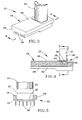
- FIGs 3 through 5 schematically represent a portion of a nozzle segment 20 that, when assembled with similarly configured segments, forms an annular-shaped HPT nozzle assembly of a gas turbine engine.
- the nozzle segment 20 is depicted as including a single vane 22 supported by a single platform 24, though it will be understood that multiple vanes can be supported by the platform 24 in combination with a second platform, resulting in a construction generally similar to that shown in Figures 1 and 2.
- the vane 22 is depicted as being hollow, though a variety of configurations are possible, including vanes configured to have struts, spars, inserts for mechanical support, baffles for enhanced internal cooling, etc. While the invention will be described in reference to a HPT nozzle assembly, it will be appreciated that the benefits of the invention can be applied to a variety of other components, including but not limited to low pressure turbine (LPT) nozzle assemblies and other hot section components of gas turbine engines.
- LPT low pressure turbine
- the platform 24 can be formed of such conventional materials as a single-crystal nickel, cobalt, or iron-base superalloy of a type suitable for use in gas turbine engines.
- Conventional practice has been to also form the vane 22 of the same or similar superalloy, such that the vane 22 and platform 24 would have similar CTE's and thermal conductivities to minimize thermally-induced strains and stresses during engine operation.
- the vane 22 is formed of a ceramic-based material, more preferably a CMC material such as a SiC/SiC (reinforcement/matrix) CMC.
- aspects of this invention are applicable to the use of a variety of ceramic-based and metallic materials, as well as intermetallic materials such as nickel aluminides (NiAl), and particularly combinations of these materials that result in combinations with significantly different CTE's and/or thermal conductivities.
- ceramic-based and metallic materials as well as intermetallic materials such as nickel aluminides (NiAl), and particularly combinations of these materials that result in combinations with significantly different CTE's and/or thermal conductivities.
- intermetallic materials such as nickel aluminides (NiAl)
- CMC materials of particular interest for the vane 22 may have CTE's and thermal conductivities in ranges of about 1.9 x10 -6 to about 2.3x10 -6 in/in ⁇ °F (about 8.7 x10 -5 to about 1.9 x10 -4 mm/mm ⁇ °C) and about 7.8 to about 19.6 BTU/hr ⁇ ft ⁇ °F (about 13.5 to about 33.9 W/mK), respectively, as compared to nickel-base superalloys whose CTE's and thermal conductivities of generally about 7.3 x10 -6 to about 8.5 x10 -6 in/in ⁇ °F (about 3.3 x10 -4 to about 3.9 x10 -4 mm/mm ⁇ °C) and about 6.8 to about 14.6 BTU/hr ⁇ ft ⁇ °F (about 11.8 to about 25.3 W/mK), respectively.
- Such differences in CTE's can cause considerable differential thermal movement between the vane 22 and platform 24, particularly during transient engine conditions when thermal conductivity and thermal mass also
- the vane 22 is seen as being supported from a surface 26 of the platform 24.
- the platform 24 would be oriented radially inward from the vane 22 within the engine, and therefore may be referred to as the inner platform (or band) of the nozzle segment 20.
- the vane 22 and surface 26 of the platform 24 are directly impinged by hot combustion gases discharged by the combustor (not shown) and flowing along the hot gas path of the engine. As such, the vane 22 and platform 24 are both subjected to intense heating during engine operation.
- a bleed air system may be employed that draws a portion of the compressed air from the engine's compressor (not shown) to cool the vane 22 and platform 24, such as through backside cooling of the platform 24 by directing bleed air at the inner surface 28 of the platform 24 opposite the vane 22, and/or by flowing bleed air through the vane 22, a portion of which may be optionally discharged through film cooling holes (not shown) on the surface of the vane 22.
- Such cooling techniques are well known in the art, and therefore do not require further explanation.
- the platform 24 is configured to include fins 30 protruding from its inner surface 28.
- the fins 30 are of a sufficient size to serve as stiffeners that increase the rigidity of the platform 24, thereby allowing the cross-sectional thickness of the platform 24 to be minimized to reduce the thermal mass of the platform 24.
- the fins 30 also preferably serve a secondary role of promoting radiation heat transfer from the platform 24 as a result of increased surface area from which heat can be radiated.
- Suitable dimensions for the fins 30 along the length of the platform 24 generally include a thickness (parallel to the surface 28) of about 2 to about 3 mm, and a height (normal to the surface 28) of about 2.5 to about 10 mm.
- the heights of the fins 30 increase immediately below the vane 22 to structurally accommodate a recess 38 (described in greater detail below) defined in the outer surface 26 of the platform 24.
- the fins 30 are preferably configured to define a substantially uniform pattern, such as the parallel pattern shown in Figure 3 through 5, with a suitable uniform spacing between fins 30 of about 6 to about 13 mm.
- the cross-sectional thickness of the platform 24 (excluding the fins 30) can be reduced by, for example, about 15 to about 25 percent while maintaining the same level of stiffness, and simultaneously resulting in a thermal mass reduction of about 10 to 20% or more for the platform 24.
- the fins 30 preferably extend the full circumferential length of the platform 24, and are integrally formed with the remainder of the platform 24 such as during a casting process of any type known and used to produce platforms for gas turbine engine nozzle assemblies. Alternatively, the fins 30 could be formed separately and attached by welding, brazing, etc.
- the vane 22 is shown in Figures 3 through 5 as mounted to the platform 24 with an interface structure 32 that provides a resilient, low thermal conductivity path between the vane 22 and platform 24.
- the interface structure 32 is represented as including a seal 34 and saddle 36, both of which are shown as being nested in the aforementioned recess 38 defined in the outer surface 26 of the platform 24.
- the recess 38 provides positive axial and tangential retention of the vane 22, the effect of which may be promoted by forming the recess 38 to extend through the inner surface 28 of the platform 24 and into the taller fins 30 shown immediately below the recess 38 in Figure 4.
- the seal 34 and saddle 36 are shown in Figure 4 as completely filling the recess 38 and continuous between the opposing surfaces of the vane 22 and platform 24.
- the seal 34 primarily provides the desired resilient interconnection between the vane 22 and platform 24, while also serving to inhibit gas leakage and heat transfer between the vane 22 and the platform 24.
- the seal 34 is preferably in the form of what may be termed a cloth seal, meaning a fabric-type sheet material woven from fibers.
- the fibers are preferably formed of an oxide dispersion strengthened (ODS) material, though the use of other high-temperature materials is foreseeable.
- ODS oxide dispersion strengthened
- the seal 34 is preferably at least 2 to 3 mm thick (normal to the surface 26) and a porosity of about 0.5 to about 1.0%.
- the seal 34 is preferably continuous beneath the vane 22, in contrast to the use of annular-shaped rope seals that surround the base of CMC vanes as proposed in the past.
- the seal 34 must also be sufficiently strong and stiff to resist compaction when under a compressive load between the vane 22 and platform 24.
- an example of a material suitable for use as the seal 34 is an ODS FeCrAl alloy commercially available from Plansee GmbH under the name PM2000.
- the saddle 36 is preferably formed of a ceramic-based material, more preferably a precast monolithic ceramic material such as SiC.
- a precast monolithic is believed to be preferred over a CMC material because of the desire for relatively precise control of the geometry of the saddle 36, such as small radii fillets joining the portions of the saddle 36 parallel to and normal to the surface 26 of the platform 24.
- the saddle 36 Without interfering with the resilient connection provided by the seal 34, the saddle 36 provides for positive retention of the vane 22 to the platform 24 by abutting a stepped shoulder 42 defined by the recess 38.
- the abutting-supporting arrangement between the edge of the saddle 36 and the shoulder 42, in combination with appropriate support at the end of the vane 22 opposite the platform 24, also inhibits compaction of the seal 34 by the saddle 36.
- the saddle 36 does not intentionally compress the seal 34.
- the ceramic material of the saddle 36 also provides additional thermal insulation within the interface structure 32 to inhibit heat transfer between the vane 22 and the platform 24.
- the portions of the saddle 36 parallel to and normal to the surface 26 of the platform 24 are each preferably at least 2.5 to 5 mm thick.
- the depth for the stepped shoulder 42 below the surface 26 of the platform 24 is preferably equal to the thickness of the portion of the saddle 36 within the recess 38 so that that portion of the saddle 36 is generally flush with the surface 26.
- the saddle 36, vane 22, and recess 38 in the surface 26 of the platform 24 are shown as having complementary configurations that form shiplap joints therebetween, as evident from Figure 4.
- both the seal 34 and saddle 36 is depicted as having L-shaped cross-sections that nest with each other and with a recess 40 defined in a wall of the vane 22, defining overlaps in both the plane parallel to the surface 26 and the plane normal to the surface 26.
- the presence of in-series shiplap joints serves to reduce gas leakage between the vane 22 and platform 24.
- the fins 30 serve to reduce the temperature of the platform 24 by promoting radiation heat transfer from the platform 24 and reducing the thermal mass of the platform 24.
- the interface structure 32 thermally insulates the vane 22 from the platform 24, thereby reducing thermal gradients within the vane 22 that could cause structural damage.
- the interface structure 32 further enables the vane 22 to be secured to the platform 24 in a manner that allows the vane 22 to expand and contract relative to the platform 24 during temperature excursions with reduced thermal-induced strains and stresses within the vane 22 that could cause the vane 22 to fracture during engine operation.
- the vane 22 is able to expand and contract both radially and laterally, the latter of which includes the circumferential and axial directions of the engine.
- the end of the vane 22 opposite the platform 24 can be secured with a second platform (corresponding to the outer platform 14 of Figure 1) in the same manner or optionally in a manner consistent with the prior art, including the use of more rigid attachment techniques.
- the interface structure 32 can potentially provide a sufficiently resilient connection between the vane 22 and its platform 24 to avoid the prior practice of constructing nozzle assemblies from multiple nozzle segments such as that shown in Figures 1 and 2, and instead forming the inner platform 24 (as well as the outer platform) as a single continuous ring.
Landscapes
- Engineering & Computer Science (AREA)
- Chemical & Material Sciences (AREA)
- Mechanical Engineering (AREA)
- General Engineering & Computer Science (AREA)
- Ceramic Engineering (AREA)
- Materials Engineering (AREA)
- Turbine Rotor Nozzle Sealing (AREA)
Applications Claiming Priority (1)
| Application Number | Priority Date | Filing Date | Title |
|---|---|---|---|
| US11/163,320 US20070122266A1 (en) | 2005-10-14 | 2005-10-14 | Assembly for controlling thermal stresses in ceramic matrix composite articles |
Publications (1)
| Publication Number | Publication Date |
|---|---|
| EP1775421A2 true EP1775421A2 (fr) | 2007-04-18 |
Family
ID=37735264
Family Applications (1)
| Application Number | Title | Priority Date | Filing Date |
|---|---|---|---|
| EP06255242A Withdrawn EP1775421A2 (fr) | 2005-10-14 | 2006-10-12 | Assemblage pour contròler les tensions thermiques dans un composite à matrice céramique |
Country Status (4)
| Country | Link |
|---|---|
| US (1) | US20070122266A1 (fr) |
| EP (1) | EP1775421A2 (fr) |
| JP (1) | JP2007107524A (fr) |
| CN (1) | CN1948719A (fr) |
Cited By (2)
| Publication number | Priority date | Publication date | Assignee | Title |
|---|---|---|---|---|
| FR2978495A1 (fr) * | 2011-07-25 | 2013-02-01 | Snecma | Carter, notamment carter intermediaire, de turboreacteur |
| WO2014158276A3 (fr) * | 2013-03-05 | 2014-12-04 | Rolls-Royce Corporation | Structure et procédé permettant de fournir adhésion et étanchéité entre des structures en céramique et des structures métalliques |
Families Citing this family (26)
| Publication number | Priority date | Publication date | Assignee | Title |
|---|---|---|---|---|
| DE102006057912A1 (de) * | 2006-12-08 | 2008-06-12 | Mtu Aero Engines Gmbh | Leitschaufelkranz sowie Verfahren zum Herstellen desselben |
| US20090067978A1 (en) * | 2007-05-24 | 2009-03-12 | Suljak Jr George T | Variable area turbine vane arrangement |
| US8240987B2 (en) * | 2008-08-15 | 2012-08-14 | United Technologies Corp. | Gas turbine engine systems involving baffle assemblies |
| US8322983B2 (en) * | 2008-09-11 | 2012-12-04 | Siemens Energy, Inc. | Ceramic matrix composite structure |
| EP2186581B1 (fr) * | 2008-11-14 | 2013-07-24 | Alstom Technology Ltd | Design d'élément de stator et procédé de coulée |
| CH700001A1 (de) * | 2008-11-20 | 2010-05-31 | Alstom Technology Ltd | Laufschaufelanordnung, insbesondere für eine gasturbine. |
| CN101581718B (zh) * | 2009-06-26 | 2012-07-25 | 陕西科技大学 | 陶瓷坯泥内应力在线软测量方法 |
| US9228445B2 (en) | 2010-12-23 | 2016-01-05 | General Electric Company | Turbine airfoil components containing ceramic-based materials and processes therefor |
| US8721290B2 (en) * | 2010-12-23 | 2014-05-13 | General Electric Company | Processes for producing components containing ceramic-based and metallic materials |
| US8777582B2 (en) | 2010-12-27 | 2014-07-15 | General Electric Company | Components containing ceramic-based materials and coatings therefor |
| US8777583B2 (en) | 2010-12-27 | 2014-07-15 | General Electric Company | Turbine airfoil components containing ceramic-based materials and processes therefor |
| FR2974593B1 (fr) * | 2011-04-28 | 2015-11-13 | Snecma | Moteur a turbine comportant une protection metallique d'une piece composite |
| US8770931B2 (en) * | 2011-05-26 | 2014-07-08 | United Technologies Corporation | Hybrid Ceramic Matrix Composite vane structures for a gas turbine engine |
| US8905711B2 (en) | 2011-05-26 | 2014-12-09 | United Technologies Corporation | Ceramic matrix composite vane structures for a gas turbine engine turbine |
| US9039364B2 (en) * | 2011-06-29 | 2015-05-26 | United Technologies Corporation | Integrated case and stator |
| US10590798B2 (en) | 2013-03-25 | 2020-03-17 | United Technologies Corporation | Non-integral blade and platform segment for rotor |
| US9040138B2 (en) * | 2013-04-29 | 2015-05-26 | General Electric Company | Composite article including composite to metal interlock and method of fabrication |
| US10287899B2 (en) * | 2013-10-21 | 2019-05-14 | United Technologies Corporation | Ceramic attachment configuration and method for manufacturing same |
| EP3023696B1 (fr) * | 2014-11-20 | 2019-08-28 | Ansaldo Energia Switzerland AG | Lance à lobes pour chambre de combustion d'une turbine à gaz |
| US20170059165A1 (en) * | 2015-08-28 | 2017-03-02 | Rolls-Royce High Temperature Composites Inc. | Cmc cross-over tube |
| US10544793B2 (en) * | 2017-01-25 | 2020-01-28 | General Electric Company | Thermal isolation structure for rotating turbine frame |
| US10697313B2 (en) | 2017-02-01 | 2020-06-30 | General Electric Company | Turbine engine component with an insert |
| US20180363488A1 (en) * | 2017-06-14 | 2018-12-20 | Rolls-Royce Corporation | Tip clearance control with finned case design |
| US10808553B2 (en) * | 2018-11-13 | 2020-10-20 | Rolls-Royce Plc | Inter-component seals for ceramic matrix composite turbine vane assemblies |
| US11428160B2 (en) | 2020-12-31 | 2022-08-30 | General Electric Company | Gas turbine engine with interdigitated turbine and gear assembly |
| CN119712236B (zh) * | 2023-09-27 | 2025-11-25 | 中国航发商用航空发动机有限责任公司 | 防热失配的组件、cmc构件及金属连接件 |
Family Cites Families (6)
| Publication number | Priority date | Publication date | Assignee | Title |
|---|---|---|---|---|
| DE69423061T2 (de) * | 1993-08-06 | 2000-10-12 | Hitachi, Ltd. | Gasturbinenschaufel, Verfahren zur Herstellung derselben sowie Gasturbine mit dieser Schaufel |
| US5634766A (en) * | 1994-08-23 | 1997-06-03 | General Electric Co. | Turbine stator vane segments having combined air and steam cooling circuits |
| US5630700A (en) * | 1996-04-26 | 1997-05-20 | General Electric Company | Floating vane turbine nozzle |
| US6200092B1 (en) * | 1999-09-24 | 2001-03-13 | General Electric Company | Ceramic turbine nozzle |
| US6464456B2 (en) * | 2001-03-07 | 2002-10-15 | General Electric Company | Turbine vane assembly including a low ductility vane |
| JP4508482B2 (ja) * | 2001-07-11 | 2010-07-21 | 三菱重工業株式会社 | ガスタービン静翼 |
-
2005
- 2005-10-14 US US11/163,320 patent/US20070122266A1/en not_active Abandoned
-
2006
- 2006-10-11 JP JP2006277217A patent/JP2007107524A/ja not_active Withdrawn
- 2006-10-12 EP EP06255242A patent/EP1775421A2/fr not_active Withdrawn
- 2006-10-13 CN CNA2006101359248A patent/CN1948719A/zh active Pending
Cited By (3)
| Publication number | Priority date | Publication date | Assignee | Title |
|---|---|---|---|---|
| FR2978495A1 (fr) * | 2011-07-25 | 2013-02-01 | Snecma | Carter, notamment carter intermediaire, de turboreacteur |
| WO2014158276A3 (fr) * | 2013-03-05 | 2014-12-04 | Rolls-Royce Corporation | Structure et procédé permettant de fournir adhésion et étanchéité entre des structures en céramique et des structures métalliques |
| US9951640B2 (en) | 2013-03-05 | 2018-04-24 | Rolls-Royce Corporation | Structure and method for providing compliance and sealing between ceramic and metallic structures |
Also Published As
| Publication number | Publication date |
|---|---|
| JP2007107524A (ja) | 2007-04-26 |
| CN1948719A (zh) | 2007-04-18 |
| US20070122266A1 (en) | 2007-05-31 |
Similar Documents
| Publication | Publication Date | Title |
|---|---|---|
| EP1775421A2 (fr) | Assemblage pour contròler les tensions thermiques dans un composite à matrice céramique | |
| EP3091187B1 (fr) | Agencement de composant de turbine avec fixation exempte de contrainte thermique | |
| US10502421B2 (en) | Combustion chamber and a combustion chamber segment | |
| EP2549188B1 (fr) | Insert pour chambre à combustion de moteur à turbine à gaz | |
| EP1347151B1 (fr) | Article pour utilisation à haute température dane une turbine à gaz et méthode de production | |
| EP2051009B1 (fr) | Panneau de revêtement intérieur de chambre à combustion en céramique pour moteur de turbine à gaz | |
| EP3155231B1 (fr) | Ensemble dispositif de suspension de carénage | |
| US10329950B2 (en) | Nozzle guide vane with composite heat shield | |
| US7452182B2 (en) | Multi-piece turbine vane assembly | |
| EP1316677B1 (fr) | Joint déflecteur thermique | |
| US11466855B2 (en) | Gas turbine engine combustor with ceramic matrix composite liner | |
| CN102588013B (zh) | 用于涡轮机构件的冲击板及装备其的构件 | |
| US8734107B2 (en) | Ceramic-based tip cap for a turbine bucket | |
| US20140212284A1 (en) | Hybrid turbine nozzle | |
| US9174275B2 (en) | Method for manufacturing a metal-ceramic composite structure and metal-ceramic composite structure | |
| US10975709B1 (en) | Turbine vane assembly with ceramic matrix composite components and sliding support | |
| EP2578807A2 (fr) | Profil aérodynamique pour système de turbine | |
| EP2538137B1 (fr) | Chambre de Combustion avec panneau de chambre de combustion tolérant à la contrainte pour moteur à turbine à gaz | |
| WO2020018090A1 (fr) | Composants hybrides comportant un matériau de fibre céramique intermédiaire | |
| EP3372790A1 (fr) | Composant doté d'un système de revêtement hybride et procédé de formation d'un composant | |
| WO2017039607A1 (fr) | Insert de pale de turbine | |
| EP3789585B1 (fr) | Profil aérodynamique avec blindage métallique | |
| EP3990754A1 (fr) | Procédé de fixation d'un composant composite à matrice céramique (cmc) sur une sous-structure métallique à l'aide de bandes de cmc | |
| WO2019046022A1 (fr) | Composant cmc hybride ayant des carénages intégrés et modulaires |
Legal Events
| Date | Code | Title | Description |
|---|---|---|---|
| PUAI | Public reference made under article 153(3) epc to a published international application that has entered the european phase |
Free format text: ORIGINAL CODE: 0009012 |
|
| AK | Designated contracting states |
Kind code of ref document: A2 Designated state(s): AT BE BG CH CY CZ DE DK EE ES FI FR GB GR HU IE IS IT LI LT LU LV MC NL PL PT RO SE SI SK TR |
|
| AX | Request for extension of the european patent |
Extension state: AL BA HR MK YU |
|
| STAA | Information on the status of an ep patent application or granted ep patent |
Free format text: STATUS: THE APPLICATION IS DEEMED TO BE WITHDRAWN |
|
| 18D | Application deemed to be withdrawn |
Effective date: 20110503 |