EP1775428A2 - Stator de soufflante - Google Patents
Stator de soufflante Download PDFInfo
- Publication number
- EP1775428A2 EP1775428A2 EP06254769A EP06254769A EP1775428A2 EP 1775428 A2 EP1775428 A2 EP 1775428A2 EP 06254769 A EP06254769 A EP 06254769A EP 06254769 A EP06254769 A EP 06254769A EP 1775428 A2 EP1775428 A2 EP 1775428A2
- Authority
- EP
- European Patent Office
- Prior art keywords
- hub
- engine
- strut
- struts
- ring
- Prior art date
- Legal status (The legal status is an assumption and is not a legal conclusion. Google has not performed a legal analysis and makes no representation as to the accuracy of the status listed.)
- Granted
Links
- 230000003068 static effect Effects 0.000 claims abstract description 10
- 230000033001 locomotion Effects 0.000 claims abstract description 5
- 238000006243 chemical reaction Methods 0.000 abstract description 13
- 230000000717 retained effect Effects 0.000 abstract 1
- 230000000694 effects Effects 0.000 description 4
- 230000006835 compression Effects 0.000 description 3
- 238000007906 compression Methods 0.000 description 3
- 230000007246 mechanism Effects 0.000 description 2
- 230000015572 biosynthetic process Effects 0.000 description 1
- 238000012217 deletion Methods 0.000 description 1
- 230000037430 deletion Effects 0.000 description 1
- 230000002708 enhancing effect Effects 0.000 description 1
- 239000012530 fluid Substances 0.000 description 1
- 239000000446 fuel Substances 0.000 description 1
- 239000000203 mixture Substances 0.000 description 1
- 230000002787 reinforcement Effects 0.000 description 1
- 238000000926 separation method Methods 0.000 description 1
- 238000004904 shortening Methods 0.000 description 1
- 230000006641 stabilisation Effects 0.000 description 1
Images


Classifications
-
- F—MECHANICAL ENGINEERING; LIGHTING; HEATING; WEAPONS; BLASTING
- F01—MACHINES OR ENGINES IN GENERAL; ENGINE PLANTS IN GENERAL; STEAM ENGINES
- F01D—NON-POSITIVE DISPLACEMENT MACHINES OR ENGINES, e.g. STEAM TURBINES
- F01D25/00—Component parts, details, or accessories, not provided for in, or of interest apart from, other groups
- F01D25/24—Casings; Casing parts, e.g. diaphragms, casing fastenings
- F01D25/246—Fastening of diaphragms or stator-rings
-
- F—MECHANICAL ENGINEERING; LIGHTING; HEATING; WEAPONS; BLASTING
- F01—MACHINES OR ENGINES IN GENERAL; ENGINE PLANTS IN GENERAL; STEAM ENGINES
- F01D—NON-POSITIVE DISPLACEMENT MACHINES OR ENGINES, e.g. STEAM TURBINES
- F01D25/00—Component parts, details, or accessories, not provided for in, or of interest apart from, other groups
- F01D25/16—Arrangement of bearings; Supporting or mounting bearings in casings
- F01D25/162—Bearing supports
-
- F—MECHANICAL ENGINEERING; LIGHTING; HEATING; WEAPONS; BLASTING
- F01—MACHINES OR ENGINES IN GENERAL; ENGINE PLANTS IN GENERAL; STEAM ENGINES
- F01D—NON-POSITIVE DISPLACEMENT MACHINES OR ENGINES, e.g. STEAM TURBINES
- F01D25/00—Component parts, details, or accessories, not provided for in, or of interest apart from, other groups
- F01D25/28—Supporting or mounting arrangements, e.g. for turbine casing
-
- F—MECHANICAL ENGINEERING; LIGHTING; HEATING; WEAPONS; BLASTING
- F01—MACHINES OR ENGINES IN GENERAL; ENGINE PLANTS IN GENERAL; STEAM ENGINES
- F01D—NON-POSITIVE DISPLACEMENT MACHINES OR ENGINES, e.g. STEAM TURBINES
- F01D9/00—Stators
- F01D9/02—Nozzles; Nozzle boxes; Stator blades; Guide conduits, e.g. individual nozzles
- F01D9/04—Nozzles; Nozzle boxes; Stator blades; Guide conduits, e.g. individual nozzles forming ring or sector
- F01D9/041—Nozzles; Nozzle boxes; Stator blades; Guide conduits, e.g. individual nozzles forming ring or sector using blades
-
- F—MECHANICAL ENGINEERING; LIGHTING; HEATING; WEAPONS; BLASTING
- F01—MACHINES OR ENGINES IN GENERAL; ENGINE PLANTS IN GENERAL; STEAM ENGINES
- F01D—NON-POSITIVE DISPLACEMENT MACHINES OR ENGINES, e.g. STEAM TURBINES
- F01D9/00—Stators
- F01D9/02—Nozzles; Nozzle boxes; Stator blades; Guide conduits, e.g. individual nozzles
- F01D9/04—Nozzles; Nozzle boxes; Stator blades; Guide conduits, e.g. individual nozzles forming ring or sector
- F01D9/042—Nozzles; Nozzle boxes; Stator blades; Guide conduits, e.g. individual nozzles forming ring or sector fixing blades to stators
-
- F—MECHANICAL ENGINEERING; LIGHTING; HEATING; WEAPONS; BLASTING
- F04—POSITIVE - DISPLACEMENT MACHINES FOR LIQUIDS; PUMPS FOR LIQUIDS OR ELASTIC FLUIDS
- F04D—NON-POSITIVE-DISPLACEMENT PUMPS
- F04D29/00—Details, component parts, or accessories
- F04D29/40—Casings; Connections of working fluid
- F04D29/52—Casings; Connections of working fluid for axial pumps
- F04D29/522—Casings; Connections of working fluid for axial pumps especially adapted for elastic fluid pumps
- F04D29/526—Details of the casing section radially opposing blade tips
-
- F—MECHANICAL ENGINEERING; LIGHTING; HEATING; WEAPONS; BLASTING
- F04—POSITIVE - DISPLACEMENT MACHINES FOR LIQUIDS; PUMPS FOR LIQUIDS OR ELASTIC FLUIDS
- F04D—NON-POSITIVE-DISPLACEMENT PUMPS
- F04D29/00—Details, component parts, or accessories
- F04D29/40—Casings; Connections of working fluid
- F04D29/52—Casings; Connections of working fluid for axial pumps
- F04D29/54—Fluid-guiding means, e.g. diffusers
- F04D29/541—Specially adapted for elastic fluid pumps
- F04D29/542—Bladed diffusers
-
- F—MECHANICAL ENGINEERING; LIGHTING; HEATING; WEAPONS; BLASTING
- F04—POSITIVE - DISPLACEMENT MACHINES FOR LIQUIDS; PUMPS FOR LIQUIDS OR ELASTIC FLUIDS
- F04D—NON-POSITIVE-DISPLACEMENT PUMPS
- F04D29/00—Details, component parts, or accessories
- F04D29/60—Mounting; Assembling; Disassembling
- F04D29/64—Mounting; Assembling; Disassembling of axial pumps
- F04D29/644—Mounting; Assembling; Disassembling of axial pumps especially adapted for elastic fluid pumps
-
- F—MECHANICAL ENGINEERING; LIGHTING; HEATING; WEAPONS; BLASTING
- F05—INDEXING SCHEMES RELATING TO ENGINES OR PUMPS IN VARIOUS SUBCLASSES OF CLASSES F01-F04
- F05D—INDEXING SCHEME FOR ASPECTS RELATING TO NON-POSITIVE-DISPLACEMENT MACHINES OR ENGINES, GAS-TURBINES OR JET-PROPULSION PLANTS
- F05D2240/00—Components
- F05D2240/10—Stators
- F05D2240/12—Fluid guiding means, e.g. vanes
-
- Y—GENERAL TAGGING OF NEW TECHNOLOGICAL DEVELOPMENTS; GENERAL TAGGING OF CROSS-SECTIONAL TECHNOLOGIES SPANNING OVER SEVERAL SECTIONS OF THE IPC; TECHNICAL SUBJECTS COVERED BY FORMER USPC CROSS-REFERENCE ART COLLECTIONS [XRACs] AND DIGESTS
- Y02—TECHNOLOGIES OR APPLICATIONS FOR MITIGATION OR ADAPTATION AGAINST CLIMATE CHANGE
- Y02T—CLIMATE CHANGE MITIGATION TECHNOLOGIES RELATED TO TRANSPORTATION
- Y02T50/00—Aeronautics or air transport
- Y02T50/60—Efficient propulsion technologies, e.g. for aircraft
Definitions
- the present invention relates to static structures and more particularly to gas turbine engine static structures utilised for aircraft propulsion.
- Fig. 1 illustrates schematically a typical gas turbine engine structure 1 in which compressors 2 are arranged on common shafts 3 with turbines 4. These compressors 2, shafts 3 and turbines 4 are located within a core casing 5 and the engine is secured through appropriate mountings to a pylon 6, itself secured to an aircraft wing 7. It will be understood that the intake reaction load 8 as an airflow 9 is drawn into the engine coupled with thrust 10 to produce pitch moments 11 in the same direction and acting in a vertical plane. It will be noted it is integral to the engine structure 1 that these moments are transferred through a fan casing 12 to an engine core 5 by opposing vertical loads on outlet guide vanes (OGVs) 13, and A frames 14. The OGVs act between the core and the fan case in order to control the flow through the engine.
- OGVs outlet guide vanes
- the outlet guide vanes and A frames are located along the length of the rear fan case 15. Intake side loads are illustrated by broken line 16. Externally of the engine's structure 1 these reaction moments are transferred to the pylon 6 through front 17, 18 and rear 19, 20 mounting reactions separated by the engine mounting span on the pylon 6. It will be understood that the couples from the intake loads 8, 16 and the reaction forces 17, 18, 19, 20 tend to bend the core of the engine structure 1. It will be understood that the reactions 18, 20 to intake side loads 16 induce a roll torque about the central axis X-X. This is transferred to the core of the engine structure predominantly by an A frame tension/compression reaction and then transferred along the core to a rear mounting through the mounting torque reaction 21 and then into the pylon 6.
- a thrust reverser is placed within an engine in order to avoid such effects as engine thrust reverser efflux impingement onto the deployed leading edge slats of the wing 7. It will be understood that in combination with the engine pylon 6 and wing 7 gully as well as engine ground clearance considerations the thrust reverser position affects the placement of the engine on the aircraft.
- the length of the rear fan case is no handicap as the common nozzle is aft of the engine rear bearing housing 22, but as gas turbine engine fan sizes increase for noise and performance objective reasons, the structure tends to favour a separation of flow jets at exit from the engine.
- These jets are mounted higher from the ground with the cold nozzle level then consistent with or forward of the wing leading edge.
- the rear fan case is between the fan and the thrust reverser, which in turn is forward of the cold nozzle. Deletion of the rear fan case allows the engine to be placed closer to the wing. This shortens the nacelle and the pylon, reducing the wing attachment loads.
- alternative engine structures must then be provided in order that the reaction loads and moments can be appropriately reconciled within the structure for operational purposes.
- a static structure for a gas turbine engine comprising a ring and a hub aligned along a principal axis X-X with a plurality of vane elements and strut members between the ring and the hub, the static structure characterised in that at least some of the vane elements are angled to be sloped with an axial lean to the principal axis and to have a tangential inclination between the ring and the hub, the ring and the hub subject to differential rotation in use causing roll torque restrained by the tangential inclination of the vane elements with the axial lean of the vane elements allowing for a differential axial movement to be restrained in use at least in part by the strut members.
- strut members there are at least three strut members. Generally for three struts, these strut members are evenly tangentially spaced at 120° apart about the principal axis.
- the strut members are secured directly to the hub.
- one strut member is arranged to be aligned with the top dead centre of the structure.
- one strut is aligned with the bottom dead centre of the structure.
- the struts are orientated in axial planes.
- the struts are orientated in non-axial planes.
- an inner strut member attachment lies directly behind an inner vane element attachment.
- an end of the strut member is integrated with an outer end of one vane spoke element. Furthermore, a web junction of the end of the strut member and the outer end of the vane is extended between the vane element and the strut.
- the rear fan case length as part of the fan to nozzle distance can be reduced or removed it is possible for the engine to be placed closer to the wing so shortening the nacelle and pylon by which the engine is secured to the wing.
- the levered pylon to wing attachment load is reduced by the reduced aerodynamic and inertial load offset from the wing.
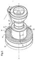
- an engine structure includes outlet guide vanes 31 secured between a fan casing 32 and a core platform 33 which may be a front bearing frame 38 which houses bearings for the shafts of the engine. Also extending between the casing 32 and the core 33 are struts or props 34 which are radially and axially orientated in order to brace the outlet guide vanes.
- the outlet guide vanes are sloped in the range 0 to 30 degrees axially and tangentially in the range 0 to 40 degrees but typically 20° of hub rotation, that is to say the outlet guide vanes 31 are angled relative to a principal axis X-X through the engine structure as well as tangentially, that it to say each vane is sloped relative to the perpendicular between the casing 32 and the core 33. Structurally, both clockwise and anti-clockwise rotation is possible. Normally the tangential slope is in the opposite direction to that depicted in Fig. 2 as depicted in Fig. 3 OGVs 41 to oppose clockwise rotation of fan blade exit air flow within a gas turbine engine incorporating the present structure.
- the struts may be rotated at the core attachment 43 to lie behind the OGV, and in line with the OGV trailing edge.
- the OGV 41 and strut 44 may then be joined at the outer ends by a web 42, at the ring 46.
- struts 34 are arranged as shown with a 120° spacing between each strut 34. Generally there are at least three struts 34 in order to achieve the necessary bracing and stiffening within the engine structure.
- a strut 34 orientation as shown is suitable.
- the struts may be rotated through 60° or as necessary to provide space for a core mount 45 placed at top dead centre. In such circumstances it will be appreciated that a strut 44 will then be presented at the bottom dead centre of the engine and so may be integrated with the gear box drive housing 47 and other structural features.
- one of the struts 34 is associated with a catcher flange 35 on a ring 36. It will be understood that this will provide improved support for the catcher flange and hence in the event of a primary mount link failure the stiffening effect provided by the present invention will provide a better connection to the pylon upon which the engine is secured.
- the present engine structure 30 provides six degrees of freedom connection. These degrees of freedom relate to vertical, side, axial, roll, pitch and yaw between the fan casing 32 and the core 33 of the structure 30.
- the struts 34 connect the hard point at the outlet guide vane and outer ring structure with the core, in this case the core hard points may be on the frame that houses the low, intermediate and high pressure rotor location bearings for the engine.
- the outlet guide vanes 31, struts 34 and casing 33 form three relatively stiff triangular fan case to core frames each comprising OGVs local to a strut, the strut itself, and the region of casing connecting the OGV and strut inner ends.
- the relatively stiff and robust frames connect the fan case to the core axially, vertically, horizontally, and in pitch and yaw.
- Roll torque created due to differential rotation of the fan case 32 and the core 33 in an operational engine is restrained by compression/tension in the tangentially leaning outlet guide vanes 31.
- the outlet guide vanes have a tangential lean so that a hoop reaction conflict is created between the concentric mounting ring 36 and core 33.
- pitch or yaw couples are accommodated by opposed pairs of axial loads in the frame formed between the slopes of the outlet guide vanes 31 in their mounting ring and the struts 34 respectively mounted at displaced positions on the core 33.
- the axially sloped strut 34 braces the outer end of the outlet guide vanes.
- the other end of the strut 34 is mounted upon an element of the core 33 to provide a robust mounting and bracing for the outlet guide vane mounting ring 36.
- the axial spacing provided between the axially sloped outlet guide vanes 31 at its attachment to the core and the axially sloped strut 34 at its attachment to the core is significantly greater than previous arrangements giving significant mechanical advantage and strength enhancements.
- junction 37 of the strut 34 and the outlet guide vanes 31 at its outer end towards the ring 36 will generally be integrated and appropriately aerodynamically shaped to achieve best effect.
- This is shown in Fig. 3 at the conjunction 42 of strut 44 and vane 41 as a web.
- the mounting provides a broader junction width with the ring 36 again enhancing stability and strength.
- the junction 42 may be extended in a web down the outlet guide vane 41 and struts 44. This will further stiffen the structure but in such circumstances it will be understood that there will be a general increase in wetted area, that is to say area exposed to the frictional drag of fan air flow. To offset this, there may be a possible reduction in profile loss.
- the three struts are placed in a "Y" formation (with one strut 44 at BDC) as shown in Fig. 3 it is convenient to locate their inner ends onto a 9 spoke core intermediate case.
- the struts could be "clocked" to locate to a 9 spoke intermediate case, or could each bridge to 2 spokes, for balance.
- the minimum number of struts is three but there may be advantages with regard to increasing the number of struts to four or more to improve the number of axial reinforcement triangles created by the axially and tangentially sloped outlet guide vanes and respective struts.
- the present engine structure could also be utilised in other situations where there are differentially rotating hub and ring structures creating a roll torque conflict.
- the axial triangles will be again be formed by a spoke arrangement comprising elements which replace the vane elements described above but similarly spokes are sloped tangentially and axially between the hub and the outer ring in order to create the resistance to the roll torque from restraint by the tangential inclination of the spoke elements whilst the axial slope of the spoke elements forms a mounting triangle with strut elements which extend to axially spaced locations on the hub to brace the mounting ring creating an overall strong structure which is well connected between the rim and the hub.
Landscapes
- Engineering & Computer Science (AREA)
- Mechanical Engineering (AREA)
- General Engineering & Computer Science (AREA)
- Structures Of Non-Positive Displacement Pumps (AREA)
Applications Claiming Priority (1)
| Application Number | Priority Date | Filing Date | Title |
|---|---|---|---|
| GBGB0520850.9A GB0520850D0 (en) | 2005-10-14 | 2005-10-14 | Fan static structure |
Publications (3)
| Publication Number | Publication Date |
|---|---|
| EP1775428A2 true EP1775428A2 (fr) | 2007-04-18 |
| EP1775428A3 EP1775428A3 (fr) | 2011-03-16 |
| EP1775428B1 EP1775428B1 (fr) | 2013-02-27 |
Family
ID=35451700
Family Applications (1)
| Application Number | Title | Priority Date | Filing Date |
|---|---|---|---|
| EP06254769A Not-in-force EP1775428B1 (fr) | 2005-10-14 | 2006-09-13 | Stator de soufflante |
Country Status (3)
| Country | Link |
|---|---|
| US (1) | US7654075B2 (fr) |
| EP (1) | EP1775428B1 (fr) |
| GB (1) | GB0520850D0 (fr) |
Cited By (2)
| Publication number | Priority date | Publication date | Assignee | Title |
|---|---|---|---|---|
| EP2578813A1 (fr) * | 2011-10-03 | 2013-04-10 | United Technologies Corporation | Tiges d'entretoise pour structure d'ailettes de guidage |
| US10443447B2 (en) | 2016-03-14 | 2019-10-15 | General Electric Company | Doubler attachment system |
Families Citing this family (26)
| Publication number | Priority date | Publication date | Assignee | Title |
|---|---|---|---|---|
| US7921634B2 (en) * | 2006-10-31 | 2011-04-12 | General Electric Company | Turbofan engine assembly and method of assembling same |
| US8844265B2 (en) | 2007-08-01 | 2014-09-30 | United Technologies Corporation | Turbine section of high bypass turbofan |
| US11486311B2 (en) | 2007-08-01 | 2022-11-01 | Raytheon Technologies Corporation | Turbine section of high bypass turbofan |
| US20150377123A1 (en) | 2007-08-01 | 2015-12-31 | United Technologies Corporation | Turbine section of high bypass turbofan |
| US11346289B2 (en) | 2007-08-01 | 2022-05-31 | Raytheon Technologies Corporation | Turbine section of high bypass turbofan |
| US11149650B2 (en) | 2007-08-01 | 2021-10-19 | Raytheon Technologies Corporation | Turbine section of high bypass turbofan |
| US11242805B2 (en) | 2007-08-01 | 2022-02-08 | Raytheon Technologies Corporation | Turbine section of high bypass turbofan |
| FR2928181B1 (fr) * | 2008-02-28 | 2010-04-02 | Airbus France | Ensemble moteur pour aeronef comprenant un turboreacteur avec des structures de renfort reliant le carter de soufflante au carter central. |
| FR2928180B1 (fr) * | 2008-02-28 | 2010-04-02 | Airbus France | Ensemble moteur pour aeronef comprenant une structure annulaire de transfert d'efforts entourant le carter central d'un turboreacteur. |
| US20140174056A1 (en) * | 2008-06-02 | 2014-06-26 | United Technologies Corporation | Gas turbine engine with low stage count low pressure turbine |
| US8221071B2 (en) * | 2008-09-30 | 2012-07-17 | General Electric Company | Integrated guide vane assembly |
| FR2952126B1 (fr) * | 2009-11-04 | 2011-12-23 | Snecma | Turbomachine a double flux pour aeronef, comprenant des moyens structuraux de rigidification du carter central |
| US8911203B2 (en) * | 2009-11-20 | 2014-12-16 | United Technologies Corporation | Fan rotor support |
| US8511987B2 (en) | 2009-11-20 | 2013-08-20 | United Technologies Corporation | Engine bearing support |
| FR2986040B1 (fr) * | 2012-01-20 | 2016-03-25 | Turbomeca | Support de palier de turbomachine |
| US10107191B2 (en) | 2012-02-29 | 2018-10-23 | United Technologies Corporation | Geared gas turbine engine with reduced fan noise |
| US20130219922A1 (en) * | 2012-02-29 | 2013-08-29 | Jonathan Gilson | Geared gas turbine engine with reduced fan noise |
| WO2014018137A2 (fr) * | 2012-04-25 | 2014-01-30 | General Electric Company | Ensemble récipient de ligne d'arbre de moteur d'aéronef et procédé d'assemblage de celui-ci |
| FR3002288B1 (fr) * | 2013-02-20 | 2022-11-25 | Snecma | Suspension d'un turboreacteur par double support arriere |
| FR3040071B1 (fr) * | 2015-08-11 | 2020-03-27 | Safran Aircraft Engines | Aube de rotor de turbomachine |
| US11555420B1 (en) | 2021-08-20 | 2023-01-17 | Raytheon Technologies Corporation | Frame connection between fan case and core housing in a gas turbine engine |
| US11674415B2 (en) | 2021-08-20 | 2023-06-13 | Raytheon Technologies Corporation | Front section stiffness ratio |
| US11608796B1 (en) | 2021-11-12 | 2023-03-21 | Raytheon Technologies Corporation | Radial strut frame connection between fan case and core housing in a gas turbine engine |
| US11708772B2 (en) | 2021-11-12 | 2023-07-25 | Raytheon Technologies Corporation | Triangular-frame connection between fan case and core housing in a gas turbine engine |
| US11686220B2 (en) | 2021-11-12 | 2023-06-27 | Raytheon Technologies Corporation | H-frame connection between fan case and core housing in a gas turbine engine |
| US20240218835A1 (en) * | 2023-01-04 | 2024-07-04 | General Electric Company | Outlet guide vanes and an accessory drive gearbox for a gas turbine engine |
Citations (1)
| Publication number | Priority date | Publication date | Assignee | Title |
|---|---|---|---|---|
| US3536414A (en) | 1968-03-06 | 1970-10-27 | Gen Electric | Vanes for turning fluid flow in an annular duct |
Family Cites Families (8)
| Publication number | Priority date | Publication date | Assignee | Title |
|---|---|---|---|---|
| US2410450A (en) * | 1943-01-30 | 1946-11-05 | Westinghouse Electric Corp | Turbine apparatus |
| US3398535A (en) * | 1966-05-25 | 1968-08-27 | Gen Electric | Engine supporting structure |
| GB1195027A (en) | 1966-11-08 | 1970-06-17 | British Aircraft Corp Ltd | Improvements relating to Cowls for Turbo-Fan Aircraft Engines. |
| CA2021087A1 (fr) | 1989-09-07 | 1991-03-08 | Eugene J. Antuna | Methode de transport d'un reacteur a double flux tres eleve avec soufflante et capot |
| GB9602130D0 (en) * | 1996-02-02 | 1996-04-03 | Rolls Royce Plc | Improved method of combining ducted fan gas turbine engine modules and aircraft structure |
| US6353789B1 (en) * | 1999-12-13 | 2002-03-05 | United Technologies Corporation | Predicting broadband noise from a stator vane of a gas turbine engine |
| JP2002349498A (ja) * | 2001-05-24 | 2002-12-04 | Ishikawajima Harima Heavy Ind Co Ltd | 低騒音ファン静翼 |
| US7370467B2 (en) * | 2003-07-29 | 2008-05-13 | Pratt & Whitney Canada Corp. | Turbofan case and method of making |
-
2005
- 2005-10-14 GB GBGB0520850.9A patent/GB0520850D0/en not_active Ceased
-
2006
- 2006-09-13 EP EP06254769A patent/EP1775428B1/fr not_active Not-in-force
- 2006-09-14 US US11/520,671 patent/US7654075B2/en active Active
Patent Citations (1)
| Publication number | Priority date | Publication date | Assignee | Title |
|---|---|---|---|---|
| US3536414A (en) | 1968-03-06 | 1970-10-27 | Gen Electric | Vanes for turning fluid flow in an annular duct |
Cited By (2)
| Publication number | Priority date | Publication date | Assignee | Title |
|---|---|---|---|---|
| EP2578813A1 (fr) * | 2011-10-03 | 2013-04-10 | United Technologies Corporation | Tiges d'entretoise pour structure d'ailettes de guidage |
| US10443447B2 (en) | 2016-03-14 | 2019-10-15 | General Electric Company | Doubler attachment system |
Also Published As
| Publication number | Publication date |
|---|---|
| US20070084218A1 (en) | 2007-04-19 |
| GB0520850D0 (en) | 2005-11-23 |
| EP1775428B1 (fr) | 2013-02-27 |
| EP1775428A3 (fr) | 2011-03-16 |
| US7654075B2 (en) | 2010-02-02 |
Similar Documents
| Publication | Publication Date | Title |
|---|---|---|
| US7654075B2 (en) | Fan static structure | |
| US12179929B2 (en) | Engine mount system for a gas turbine engine | |
| US7845158B2 (en) | Turbine engine mounting arrangement | |
| US8511604B2 (en) | Gas turbine engine with low stage count low pressure turbine | |
| US8807477B2 (en) | Gas turbine engine compressor arrangement | |
| CA2849013C (fr) | Moteur a turbine a gaz comportant une turbine a basse pression a faible nombre d'etages | |
| US8511605B2 (en) | Gas turbine engine with low stage count low pressure turbine | |
| US20120121390A1 (en) | Gas turbine engine compressor arrangement | |
| EP2944790A1 (fr) | Agencement de compresseur de turbine à gaz | |
| EP2969758B1 (fr) | Système de montage de moteur | |
| US5370501A (en) | Fan for a ducted fan gas turbine engine | |
| EP2610462B1 (fr) | Moteur à turbine à gaz | |
| US10974813B2 (en) | Engine nacelle for an aircraft | |
| CN111350609A (zh) | 气体涡轮引擎的安装 | |
| CN114379795A (zh) | 推进发动机和整流罩 |
Legal Events
| Date | Code | Title | Description |
|---|---|---|---|
| PUAI | Public reference made under article 153(3) epc to a published international application that has entered the european phase |
Free format text: ORIGINAL CODE: 0009012 |
|
| AK | Designated contracting states |
Kind code of ref document: A2 Designated state(s): AT BE BG CH CY CZ DE DK EE ES FI FR GB GR HU IE IS IT LI LT LU LV MC NL PL PT RO SE SI SK TR |
|
| AX | Request for extension of the european patent |
Extension state: AL BA HR MK YU |
|
| PUAL | Search report despatched |
Free format text: ORIGINAL CODE: 0009013 |
|
| AK | Designated contracting states |
Kind code of ref document: A3 Designated state(s): AT BE BG CH CY CZ DE DK EE ES FI FR GB GR HU IE IS IT LI LT LU LV MC NL PL PT RO SE SI SK TR |
|
| AX | Request for extension of the european patent |
Extension state: AL BA HR MK RS |
|
| RIC1 | Information provided on ipc code assigned before grant |
Ipc: F01D 9/04 20060101ALI20110208BHEP Ipc: F01D 25/28 20060101ALI20110208BHEP Ipc: F04D 29/54 20060101ALI20110208BHEP Ipc: F01D 25/16 20060101AFI20061114BHEP Ipc: F01D 25/24 20060101ALI20110208BHEP |
|
| 17P | Request for examination filed |
Effective date: 20110816 |
|
| 17Q | First examination report despatched |
Effective date: 20110914 |
|
| AKX | Designation fees paid |
Designated state(s): DE FR GB |
|
| GRAP | Despatch of communication of intention to grant a patent |
Free format text: ORIGINAL CODE: EPIDOSNIGR1 |
|
| GRAS | Grant fee paid |
Free format text: ORIGINAL CODE: EPIDOSNIGR3 |
|
| GRAA | (expected) grant |
Free format text: ORIGINAL CODE: 0009210 |
|
| AK | Designated contracting states |
Kind code of ref document: B1 Designated state(s): DE FR GB |
|
| REG | Reference to a national code |
Ref country code: GB Ref legal event code: FG4D |
|
| REG | Reference to a national code |
Ref country code: DE Ref legal event code: R096 Ref document number: 602006034721 Country of ref document: DE Effective date: 20130425 |
|
| PLBE | No opposition filed within time limit |
Free format text: ORIGINAL CODE: 0009261 |
|
| STAA | Information on the status of an ep patent application or granted ep patent |
Free format text: STATUS: NO OPPOSITION FILED WITHIN TIME LIMIT |
|
| 26N | No opposition filed |
Effective date: 20131128 |
|
| REG | Reference to a national code |
Ref country code: DE Ref legal event code: R097 Ref document number: 602006034721 Country of ref document: DE Effective date: 20131128 |
|
| REG | Reference to a national code |
Ref country code: FR Ref legal event code: PLFP Year of fee payment: 10 |
|
| REG | Reference to a national code |
Ref country code: FR Ref legal event code: PLFP Year of fee payment: 11 |
|
| REG | Reference to a national code |
Ref country code: FR Ref legal event code: PLFP Year of fee payment: 12 |
|
| REG | Reference to a national code |
Ref country code: FR Ref legal event code: PLFP Year of fee payment: 13 |
|
| PGFP | Annual fee paid to national office [announced via postgrant information from national office to epo] |
Ref country code: GB Payment date: 20190927 Year of fee payment: 14 |
|
| PGFP | Annual fee paid to national office [announced via postgrant information from national office to epo] |
Ref country code: DE Payment date: 20190927 Year of fee payment: 14 |
|
| REG | Reference to a national code |
Ref country code: DE Ref legal event code: R119 Ref document number: 602006034721 Country of ref document: DE |
|
| GBPC | Gb: european patent ceased through non-payment of renewal fee |
Effective date: 20200913 |
|
| PG25 | Lapsed in a contracting state [announced via postgrant information from national office to epo] |
Ref country code: DE Free format text: LAPSE BECAUSE OF NON-PAYMENT OF DUE FEES Effective date: 20210401 |
|
| PG25 | Lapsed in a contracting state [announced via postgrant information from national office to epo] |
Ref country code: GB Free format text: LAPSE BECAUSE OF NON-PAYMENT OF DUE FEES Effective date: 20200913 |
|
| PGFP | Annual fee paid to national office [announced via postgrant information from national office to epo] |
Ref country code: FR Payment date: 20220926 Year of fee payment: 17 |
|
| P01 | Opt-out of the competence of the unified patent court (upc) registered |
Effective date: 20230528 |
|
| PG25 | Lapsed in a contracting state [announced via postgrant information from national office to epo] |
Ref country code: FR Free format text: LAPSE BECAUSE OF NON-PAYMENT OF DUE FEES Effective date: 20230930 |