EP1775455A2 - Moteur à combustion à autoallumage avec chambres de combustion pour allumage à haute pression - Google Patents
Moteur à combustion à autoallumage avec chambres de combustion pour allumage à haute pression Download PDFInfo
- Publication number
- EP1775455A2 EP1775455A2 EP06019137A EP06019137A EP1775455A2 EP 1775455 A2 EP1775455 A2 EP 1775455A2 EP 06019137 A EP06019137 A EP 06019137A EP 06019137 A EP06019137 A EP 06019137A EP 1775455 A2 EP1775455 A2 EP 1775455A2
- Authority
- EP
- European Patent Office
- Prior art keywords
- cooled plate
- internal combustion
- combustion engine
- engine according
- cylinder
- Prior art date
- Legal status (The legal status is an assumption and is not a legal conclusion. Google has not performed a legal analysis and makes no representation as to the accuracy of the status listed.)
- Granted
Links
Images



Classifications
-
- F—MECHANICAL ENGINEERING; LIGHTING; HEATING; WEAPONS; BLASTING
- F02—COMBUSTION ENGINES; HOT-GAS OR COMBUSTION-PRODUCT ENGINE PLANTS
- F02F—CYLINDERS, PISTONS OR CASINGS, FOR COMBUSTION ENGINES; ARRANGEMENTS OF SEALINGS IN COMBUSTION ENGINES
- F02F1/00—Cylinders; Cylinder heads
- F02F1/24—Cylinder heads
- F02F1/26—Cylinder heads having cooling means
- F02F1/36—Cylinder heads having cooling means for liquid cooling
- F02F1/40—Cylinder heads having cooling means for liquid cooling cylinder heads with means for directing, guiding, or distributing liquid stream
-
- F—MECHANICAL ENGINEERING; LIGHTING; HEATING; WEAPONS; BLASTING
- F02—COMBUSTION ENGINES; HOT-GAS OR COMBUSTION-PRODUCT ENGINE PLANTS
- F02F—CYLINDERS, PISTONS OR CASINGS, FOR COMBUSTION ENGINES; ARRANGEMENTS OF SEALINGS IN COMBUSTION ENGINES
- F02F1/00—Cylinders; Cylinder heads
- F02F1/02—Cylinders; Cylinder heads having cooling means
- F02F1/10—Cylinders; Cylinder heads having cooling means for liquid cooling
- F02F1/16—Cylinder liners of wet type
-
- F—MECHANICAL ENGINEERING; LIGHTING; HEATING; WEAPONS; BLASTING
- F01—MACHINES OR ENGINES IN GENERAL; ENGINE PLANTS IN GENERAL; STEAM ENGINES
- F01P—COOLING OF MACHINES OR ENGINES IN GENERAL; COOLING OF INTERNAL-COMBUSTION ENGINES
- F01P3/00—Liquid cooling
- F01P3/12—Arrangements for cooling other engine or machine parts
- F01P3/14—Arrangements for cooling other engine or machine parts for cooling intake or exhaust valves
-
- F—MECHANICAL ENGINEERING; LIGHTING; HEATING; WEAPONS; BLASTING
- F02—COMBUSTION ENGINES; HOT-GAS OR COMBUSTION-PRODUCT ENGINE PLANTS
- F02F—CYLINDERS, PISTONS OR CASINGS, FOR COMBUSTION ENGINES; ARRANGEMENTS OF SEALINGS IN COMBUSTION ENGINES
- F02F1/00—Cylinders; Cylinder heads
- F02F1/24—Cylinder heads
- F02F2001/249—Cylinder heads with flame plate, e.g. insert in the cylinder head used as a thermal insulation between cylinder head and combustion chamber
Definitions
- the invention relates to a self-igniting internal combustion engine with combustion chambers for high ignition pressures according to the preamble of claim 1.
- the invention is based on the assumption that the combustion chamber seal usual today must be taken over by the underside of the cylinder head in future engines with greatly increased ignition pressures of a separate component. It is a arranged between the combustion chamber and the cylinder head the top surface of the combustion chamber forming separate, with the crankcase and / or the cylinder liner positively and gastight connected cooled plate in which the valve seats at least one inlet valve and at least one outlet valve are arranged and the is penetrated by the at least one injection valve.
- the advantage of such a component is, on the one hand, that the positive connection of the cooled plate with the crankcase and / or the cylinder liner can be made directly to the combustion chamber boundary, whereby the deflection at pressurization already considerably minimized compared to today's standard cylinder heads due to the much smaller spans
- the use of this separate from the crankcase, cylinder head and possibly the cylinder liner component opens up completely new possibilities in terms of material selection.
- the cooling of the cooled plate is carried out by the cooling medium provided for the cooling of the crankcase and the cylinder head, so that the cooled plate can be advantageously integrated into the existing cooling system.
- a further advantage of the cooled plate according to the invention is that, due to the better accessibility for the mechanical processing, cooling channels can be introduced into the cooled plate which permit a significantly improved cooling of the combustion chamber roof and the valve seats compared to conventional cylinder heads.
- the cooling channels can be advantageously formed as outgoing from the peripheral side of the cooled plate holes, which advantageously extend in the cooled plate that they cut other holes and form a connected system of holes. In this case, at least some of the bores are reclosed towards the peripheral side in order to simplify advantageously the inflow and outflow of the coolant.
- the supply of the cooled plate with coolant can be done easily and thus advantageously so that in the peripheral side and / or in the protruding edge region of the top surface of the combustion chamber forming flat side of the cooled plate and / or the top surface opposite flat side of the cooled plate inflow and / / or outflow openings are provided and the supply of the cooled plate with coolant directly and / or via the crankcase and / or via the cylinder head. This opens up the possibility of optimally adapting the coolant flow to the respective structural conditions.
- the cooled plate according to the invention can be used both in bushing-free combustion chambers and in combustion chambers which have a sleeve arranged in a cylinder bore.
- a socket it is particularly advantageous to use one which has a collar which is supported on a balcony in the cylinder bore.
- the inflow and outflow openings in the cooled plate are formed as bores corresponding to corresponding openings in the cylinder head or in the collar of the bush or in the crankcase or in a separate coolant manifold and the cooling channels in Connect the cooled plate to the coolant chambers in the cylinder head, crankcase or separate coolant manifold.
- sealing means can be provided in each case in the crossing area, which reliably prevent leakage of the cooling medium.
- the outer diameter of the inner diameter of the Combustion chamber substantially corresponds to the cylindrical projection is in the assembled state in the interior of the cylinder bore or the socket, so that the cooled plate engages the upper edge of the combustion chamber angle. It is particularly conducive to the seal to choose the diameter of the cylindrical projection so that there is an interference fit between it and the combustion chamber diameter. In addition, it may be advantageous for sealing the combustion chamber to provide a seal between the combustion chamber overlapping part of the cooled plate and the crankcase or the Buchsenbund.
- connection of the cooled plate with the crankcase or, if present, the bushing collar is advantageously accomplished by screwing the cooled plate to the crankcase or the bushing collar by means of screws, the screws are advantageous as close to the combustion chamber edge to arrange the deflection of the cooled plate during the Minimize ignition events.
- combustion chambers having a socket, by means of an internal thread on the upper edge of the sleeve and an external thread on the circumference of the cylindrical extension to screw the cooled plate to the socket, so that the connection between the socket and the cooled plate in particularly favorable manner takes place directly on the combustion chamber edge.
- Another simple and therefore cheap way to connect the cooled plate with the socket consists of welding these two components together.
- the cooled plate may be provided on its side facing the combustion chamber with a coating of low thermal conductivity and / or high wear resistance, wherein the coating with low thermal conductivity minimizes the heat loss of the combustion chamber gas and thus advantageously increases the efficiency and a wear-reducing coating on the valve seats positively influences the service life.
- both the cooling channels and the coolant supply and coolant discharges can be particularly simple and therefore advantageous by z.
- the cylinder head which adjoins the cooled plate on the side facing away from the combustion chamber, can be designed as a cylinder head assigned to a cylinder or as a continuous cylinder head assigned to several or all cylinders and contains, in addition to the gas exchange channels, at least one injection valve and the guides for the inlet cylinder head. and exhaust valves.
- the cylinder head is advantageously configured to pressurize the cooled plate at least in the region of its center.
- the coolant chambers are divided, extending at least perpendicular to the flat side of the cooled plate bulkheads, which derive particular occurring in the center of the cooled plate forces in the cylinder head fasteners in the crankcase.
- the use of the cooled plate according to the invention opens up possibilities of material selection with respect to the cylinder head, which did not exist in conventional internal combustion engines for commercial vehicles for reasons of strength, then light metal alloys can be used for the cylinder head, which reduce the weight in an advantageous manner and have much better properties with respect to the Heat transport have.
- a control and actuation module For controlling and actuating the gas exchange valves and the injection valves, a control and actuation module is provided which extends over a plurality of cylinders, preferably over all cylinders of a series engine or over all cylinders of a cylinder bank of a V-engine and which contains at least one camshaft and the actuators for the gas exchange valves and encloses the actuators for the injectors.
- the control and actuation module is connected to the lubricant circuit and has a housing cover, via which the actuators for the gas exchange valves and the injectors are accessible.
- control and actuation module fastened by means of detachable connections to the cylinder head or the cylinder heads, the construction detached from the cylinder head offers new possibilities in the choice of material.
- a complete or at least partial execution in plastic allows an advantageous weight reduction and simplifies the production as a plastic injection molded part.
- the control and actuation module can advantageously an all combustion chambers or integrated all the combustion chambers of a cylinder bank common charge air pipe.
- Fig. 1 shows a combustion chamber 1 of a self-igniting internal combustion engine, which consists of a cylinder liner 2, a piston 3 and a cooled plate 4.
- the cylinder liner 2 is arranged in a known manner in the crankcase 5 and surrounded in the region of the combustion chamber 1 by coolant leading rooms 6 for cooling the combustion chamber walls.
- the piston 3 acts via a connecting rod 7 on a crankshaft 8, which is mounted in the crankcase 5 is (not shown).
- the combustion chamber 1 is closed by the cooled plate 4, which essentially has the outer diameter of a bushing collar 9 arranged on the cylinder head end of the cylinder liner 2.
- a cylindrical projection 10 is arranged to the combustion chamber 1, the diameter of which substantially corresponds to the inner diameter of the cylinder liner 2, so that the cooled plate 4, the cylinder head side edge of the cylinder liner 2 engages angularly.
- cooling channels 11 Inside the cooled plate 4 cooling channels 11 are arranged, in which a cooling medium circulates.
- the cooled plate 4 is positively and gas-tightly connected to the cylinder liner 2.
- valve seats (not visible in Fig. 1) arranged, which cooperate with the valve plates 12 of the gas exchange valves 13.
- the fuel supply via an opening 20 which passes through the cooled plate 4 in its center from the side facing away from the combustion chamber 1 in the direction of the combustion chamber 1 and in which an injection valve (not shown in Fig. 1) is arranged.
- the arrangement of the injection valve in the opening 20 is made such that the injection valve, possibly with the interposition of a sealant, the combustion chamber gas-tight and with its injection nozzle opening (not shown) projects into it.
- the cylinder head 14 is fastened in a conventional manner by means of screws (not shown) which project through the cylinder head 14 in the direction of the crankcase 5 and fix it on the crankcase 5.
- the gas channels (not shown) for intake air or the combustion gases, the valve guides (not shown) for the valve stems 15 of the gas exchange valves 13 and a coolant space 16 for cooling the cylinder head 14 or its built-in parts are arranged in the cylinder head 14 in a known manner.
- the space in the cylinder head 14 is divided into a cellular structure, on the one hand by connecting holes 21 allows targeted coolant management and on the other hand, has a high rigidity, the a deflection of the cooled plate 4 counteracts in the ignition phase.
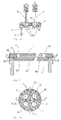
- FIG. 1 An external view of the cylinder liner 2 with attached cooled plate 4, Fig. 2 in side view and Fig. 3 in plan view.
- the cooled plate 4 is screwed to the bushing collar 9 by means of screws 19, and corresponds in diameter to the outer diameter
- the gas exchange valves 13 and the opening 20 are arranged for the injection valve.
- FIG. 5 shows a section along the line CC in FIG. 2. Starting from opposite sides of the circumference of the cooled plate 4, boreholes 11.1, 11.2, 11.5, 11.6 forming two pairs of bores run toward each other, wherein each of the pairs of bores has a " X ", so cut the holes of a hole pair.
- the arrangement of the bore pairs relative to the arrangement of the openings for the gas exchange valves 13, whose centers essentially form the vertices of a square, is made such that the intersection of a pair of holes between two adjacent openings for the gas exchange valves 13.
- the holes 11.1, 11.2, 11.5, 11.6 of each pair of holes extend from the respective points of intersection viewed in the direction of the center of the cooled plate 4 again apart and intersect the holes of the respective opposing hole pair on a line through the center of the cooled plate 4th
- the so-forming network of connected holes 11.1 - 11.6 forms the cooling channels 11 which, as will be explained in more detail below, can be connected in different ways with the cooling system of the internal combustion engine.
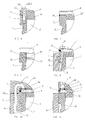
- the screw connection of the cylinder liner 2 to the cooled plate 4 described above in connection with FIGS. 1 to 5 is shown in a detail view in FIG. 6.
- the cooled plate 4 is located, the combustion chamber 1 in the direction of the cylinder head 14 (not shown in FIG. 6) finally, in the region of the bushing collar 9 on the cylinder liner 2 and surrounds the inner edge of the bushing collar 9 angle-shaped.
- the screw 19 cooperates with a corresponding thread 23 in the bushing collar 9 and sets the cooled plate 4 on the bushing collar 9.
- the diameter of the cylindrical projection 10 of the cooled plate 4 in conjunction with the inner diameter of the cylinder liner 2 can be designed so that there is an interference fit.
- FIG. 8 shows another way to screw the cooled plate 4 with the bushing collar 9, to the cylindrical projection 10 of the cooled plate 4, an external thread 25 is provided which cooperates with an internal thread 26 on the cylinder head side edge of the bushing collar 9.
- connection with Figures 6 to 8 between the cooled plate 4 and the cylinder liner are only examples, it can be with the skilled person available many different compounds between these two components, but in particular between the cooled plate and the Crankcase, in one embodiment of the combustion chamber without cylinder liner realize.
- cooling channels 11 forming holes 11.1-11.6 are connected to the cooling system of the internal combustion engine. This connection can be done in different ways. Some ways to feed the cooling channels 11 in the cooled plate 4 with coolant or to remove coolant therefrom are shown by way of example in the detailed illustrations in FIGS. 9-11.
- the sectional view in Fig. 9 shows this simplifies the already known arrangement of cooled plate 4 and cylinder liner 2.
- the cylinder liner 2 is located in the cylinder bore in the crankcase 5, wherein for cooling the walls of the combustion chamber 1 coolant leading spaces 6 between the crankcase 5 and cylinder liner 2 are formed.
- the cooled plate 4 has a bore 11 forming a cooling channel which extends from the peripheral side 27 of the cooled plate 4 radially inwardly. To the peripheral side 27 towards the cooling channel 11 is closed by means of a pressed ball 28.
- connection of the cooling channel 11 to the cooling system of the internal combustion engine is through a supply bore 29 accomplished, which passes through the bushing collar 9 of the cylinder liner 2 and is aligned with a connection bore 30 in resting on the bushing collar 9 edge region of the cooled plate 4, wherein the connection bore 30 opens into the cooling channel 11.
- a supply bore 29 accomplished, which passes through the bushing collar 9 of the cylinder liner 2 and is aligned with a connection bore 30 in resting on the bushing collar 9 edge region of the cooled plate 4, wherein the connection bore 30 opens into the cooling channel 11.
- similar feed bores and thus aligned connection bores may be provided at several points of the cooled plate 4 and cooperate with corresponding cooling channels to ensure efficient cooling.
- FIG. 10 A further possibility of supplying coolant from the crankcase 5 to the cooled plate 4 is shown schematically in a sectional drawing, FIG. 10.
- the already described arrangement of cylinder liner 2 and cooled plate 4 is shown.
- This arrangement is enclosed on the one hand by the crankcase 5 and the other hand arranged on the crankcase 5 cylinder head 14.
- In the crankcase 5 runs a connecting channel 31 from a arranged in the crankcase 5 coolant passage 32 to the dividing line between the cylinder head 14 and crankcase 5 and goes there in a cylinder head 14 arranged connection channel 33 via, which in turn via a connection opening 34 in the analogous to the example of FIG. 9 in the cooled plate 4 arranged cooling channel 11 opens.
- sealing means 35 are provided to seal the transition between the crankcase 5 and cylinder head 14 on the one hand and the cylinder head 14 and cooled plate 4 on the other hand.
- similar coolant supply to the cooled plate 4 may be provided at several points.
- FIG. 11 shows in simplified form a coolant supply to the cooled plate 4 from the cylinder head 14 of the internal combustion engine.
- the arrangement shown also in this case comprises a cylinder liner 2 with which the cooled plate 4 is connected in one of the ways described above.
- the combination of cylinder liner 2 and cooled plate 4 superimposed in a cylinder bore in the crankcase 5, such that the cylinder head side flat side of the cooled plate 4, with the cylinder head 14 adjacent side of the crankcase 5 is aligned.
- a connection between the coolant chamber 16 and the cooling channel 11 in the cooled plate 4 is provided by the coolant chamber 16 arranged in the cylinder head 14 via a connection opening 36 to be cooled on the cooled plate 4, which is in alignment with a coolant connection 37 in the cooled plate 4 created.
- the cooling channel 11 formed from the peripheral side of the cooled plate 4 and formed in the form of a bore is, as in the examples described above, by a pressed ball 28 near the peripheral side locked.
- a sealing means 35 is arranged around the coolant connection 37.
- several similar connections can be provided between the coolant chamber 16 in the cylinder head 14 and cooling channels 11 in the cooled plate 4.
- the coolant discharge from the cooled plate 4 to the crankcase 5 or to the cylinder head 14 may be similar to the coolant feeds described in the examples, so that a separate illustration of the coolant discharges can be waived.
- the above-described principles of the coolant supply of the cooled plate 4 are of course equally suitable for internal combustion engines with cylinder liners and bushingless internal combustion engines.
- FIGS. 12 and 13 shows a section along the line D-D (FIG. 5) and FIG. 13 shows a section along the line E-E (FIG. 5).
- Fig. 12 shows, starting from a first coolant chamber 16.1, which is part of the coolant chamber 16 in the cylinder head 14, an inlet bore 38 which connects the first coolant chamber 16.1 with the bore 11.1 in the cooled plate 4.
- the bore 11.1 which is closed to the narrow side of the cooled plate 4 through a ball 28, cuts at the point X, the bore 11.2 whose further course to the point Y in the sectional view is.
- the bore 11.2 intersects the bore 11.6 whose course is shown in the right half of FIG.
- the bore 11.6 cuts at the point Z the bore 11.5 and is closed on the narrow side of the cooled plate 4 with a pressed-in bore 11.6 ball 28.
- Via a drain hole 39 a connection between the bore 11.6 and a second coolant chamber 16.2 is made in the cylinder head 14, which is located downstream of the first coolant chamber 16.1 and also part of the coolant chamber 16.
- FIG. 13 shows a sectional view deviating from the illustration in FIG. 12 in FIG. 5 with EE.
- the bore 11.2 intersects both the bore 11.6 and the bore 11.3, whose course is shown in the right half of Fig. 13.
- the bore 11.3 is also closed near the peripheral side with a ball 28.
- a further drain hole 40 is provided which connects the bore 11.3 with a third coolant chamber 16.3 which is also part of the coolant chamber 16 and downstream of the coolant chamber 16.1.
- connections 21 between the individual parts of the coolant chamber 16 (FIG. 1) and the connections between the coolant chamber 16 and the cooling channels 11 are designed in this way are that a staggered according to the heat load of the cooled plate 4 and cylinder head 14 results in heat dissipation, while the heat load and thus the heat dissipation at the combustion chamber boundary is greatest and decreases with increasing distance from the combustion chamber.
- the cooled plate 4 may be made of a high strength metal alloy e.g. high-strength forged steel exist that could not be used for conventional cylinder heads for structural, manufacturing and financial reasons.
- the cylinder head is made of simpler materials, such as, for example, because of the low stress experienced by conventional cylinder heads. Aluminum can be produced, which in addition to cost advantages also bring weight advantages.
- valve seats for the gas exchange valves 13 can be incorporated directly into the cooled plate, so that can be dispensed with the pressing of valve seat rings.
- the separation of the combustion chamber seal from the cylinder head also allows or simplifies wear-reducing and / or efficiency-increasing measures on the combustion chamber roof.
- FIG. 14 shows in a partial view a section along the line F-F in FIG. 3.
- a cooled plate 4 is screwed to the bushing collar 9 of a cylinder liner 2, the cylinder liner 2 being a cooled plate 4 and a piston 3 (FIG. 1) forming the combustion chamber 1.
- the combustion chamber 1 covering the side of the cooled plate 4 with a ceramic coating 42 to provide.
- Such ceramic coatings can be applied in many different ways; the methods used for this purpose are known to the person skilled in the art. Of course, other than ceramic coatings are conceivable.
- the cooled plate 4 In order to obtain different material properties in different planes of the cooled plate, as shown in section in a partial view along the line GG (FIG. 16), it is possible to construct the cooled plate 4 from layers.
- a first package of two layers 45 is provided, wherein the two layers 45 consist of metal plates which form a rigid composite and contain both inflow openings 43 and outflow openings 44, via which the cooling liquid from the cylinder head 14 analogously to the example of FIG flow or can flow to this.
- the recesses 47 To the two layers 45 is followed in the direction of the combustion chamber 1, a third layer 46, the recesses 47, for example in the form of free distances.
- the recesses 47 correspond to the feed openings 43 and the discharge openings 44 and form the cooling channels of the cooled plate 4.
- the third layer 46 In the choice of material of the third layer 46 may be geared to a good workability, because this layer 46 anyway because of the recesses 47 to the flexural rigidity of the Can contribute together.
- the fourth layer 48 in the direction of the combustion chamber 1, like the first two layers 45, consists of a material of high flexural stiffness, while the fifth layer 49 in the direction of the combustion chamber has high hardness and low thermal conductivity.
- the valve seats of the gas exchange valves (not shown in Fig. 15) are incorporated.
- the coolant channels 11 are arranged at valve holes 51 spaced slightly in the region of the valve webs 51.1 and optimize the cooling effect in this area. In addition to the above-described free-dancing of the coolant channels, they can also be recessed in relief in the parallel plates.
- either a continuous all combustion chambers common or more each at least one combustion chamber associated cylinder heads are provided, wherein the cylinder head or the cylinder heads only the gas exchange channels, the cooling channels, the conventional engine valves and the Includes intake for the injectors.
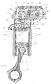
- the control and operating mechanisms for the gas exchange valves and for the injection valves conventionally contained in the cylinder head or in the cylinder heads in conventional engine designs are, as shown in a sectional drawing along the line AA (FIG. 2) in a control and actuation module, as shown in FIG arranged, which is common to all combustion chambers. Since the illustration in FIG. 17 differs from the representation in FIG.
- the control and actuation module 52 has a common to all combustion chambers and thus also all cylinder heads 14 carrier 53 on which in a trough-shaped portion 54, a camshaft 55 is rotatably mounted.
- the drive of the camshaft 55 is effected in a conventional manner by a driven via the crankshaft 8, not shown in the diagram gear assembly, it may be a gear drive, a chain or a toothed belt.
- the camshaft 55 acts in a known manner via its cams 56 on roller rocker arm 57, which rotatably on a common carrier 53 mounted axis 58 are arranged, such that the cams 56 of the camshaft 55 act on the cam-side ends 57.1 of the rocker arm 57.
- valve bridges 59 the gas exchange valves 13 and thereby open or close on the valve plate 12, the gas exchange channels (not shown).
- the combustion chambers are supplied with fuel via injection valves 60 arranged in the cylinder head 14, which are connected via pipe connections (not shown) to an injection system (not shown).
- the injection system may be e.g. to trade a common rail injection system.
- the actuation of the injectors via an electronic control (not shown) by electrical means, as is common in common rail injection systems.
- a central lubricant bore 61 is provided, which is supplied by the lubricant circuit of the internal combustion engine (not shown) with lubricant and in turn with the lubrication points in the control and actuation module 52 via lubricant channels (not shown) is directly or indirectly ally. Excess lubricant is collected in the common carrier 53 and returned via a return line (not shown) in the oil pan of the internal combustion engine (not shown).
- a cover 62 is provided, which is screwed to the common carrier 53 and closes off the interior of the control and actuation module 52 from the surrounding atmosphere.
- the above description of the mechanisms for actuating the gas exchange valves and the injectors is to be understood as exemplary only.
- the actuation arrangement for the gas exchange valves may of course also be an electronically controlled arrangement which actuates the gas exchange valves individually via actuators actuated electrically or hydraulically.
- the common rail injection system described is only one possible embodiment, it may of course also be a pump-nozzle system or a pump-line-nozzle system.
- control and actuation module 52 described above in connection with FIG. 17 does not necessarily have to be separated from the cylinder head 14, the functionality of the control and actuation module can of course also be integrated into the cylinder head under certain conditions.
- the actuator assembly for the gas exchange valves in the cylinder heads would be advantageous, as is customary in such constructions.
Landscapes
- Engineering & Computer Science (AREA)
- Chemical & Material Sciences (AREA)
- Combustion & Propulsion (AREA)
- Mechanical Engineering (AREA)
- General Engineering & Computer Science (AREA)
- Cylinder Crankcases Of Internal Combustion Engines (AREA)
Priority Applications (1)
| Application Number | Priority Date | Filing Date | Title |
|---|---|---|---|
| PL06019137T PL1775455T3 (pl) | 2005-10-11 | 2006-09-13 | Samozapalny silnik spalinowy z komorami spalania do wysokich ciśnień zapłonu |
Applications Claiming Priority (1)
| Application Number | Priority Date | Filing Date | Title |
|---|---|---|---|
| DE102005048566A DE102005048566A1 (de) | 2005-10-11 | 2005-10-11 | Selbstzündende Brennkraftmaschine mit Brennräumen für hohe Zünddrücke |
Publications (3)
| Publication Number | Publication Date |
|---|---|
| EP1775455A2 true EP1775455A2 (fr) | 2007-04-18 |
| EP1775455A3 EP1775455A3 (fr) | 2013-01-30 |
| EP1775455B1 EP1775455B1 (fr) | 2015-07-29 |
Family
ID=37667413
Family Applications (1)
| Application Number | Title | Priority Date | Filing Date |
|---|---|---|---|
| EP06019137.6A Not-in-force EP1775455B1 (fr) | 2005-10-11 | 2006-09-13 | Moteur à combustion éà autoallumage avec chambres de combustion pour allumage à haute pression |
Country Status (6)
| Country | Link |
|---|---|
| US (1) | US7533648B2 (fr) |
| EP (1) | EP1775455B1 (fr) |
| CN (1) | CN1948739B (fr) |
| DE (1) | DE102005048566A1 (fr) |
| PL (1) | PL1775455T3 (fr) |
| RU (1) | RU2405949C2 (fr) |
Cited By (3)
| Publication number | Priority date | Publication date | Assignee | Title |
|---|---|---|---|---|
| DE102010020877A1 (de) * | 2010-05-18 | 2011-11-24 | Wolfgang Müller-Mudrony | Doppelzylinder-Zweitaktmotor mit Gleichstromspülung |
| US12228091B1 (en) | 2023-11-09 | 2025-02-18 | Philip Franklin Gaziano | Internal combustion engine |
| US12421875B2 (en) | 2023-11-09 | 2025-09-23 | Philip Franklin Gaziano | Internal combustion engine |
Families Citing this family (13)
| Publication number | Priority date | Publication date | Assignee | Title |
|---|---|---|---|---|
| US20090007775A1 (en) * | 2007-03-07 | 2009-01-08 | Seymour John C | Engine for Aeronautical Applications II |
| AT511601B1 (de) * | 2011-07-28 | 2013-01-15 | Avl List Gmbh | Zylinderkopf mit flüssigkeitskühlung |
| CN102383965B (zh) * | 2011-08-08 | 2016-03-16 | 靳北彪 | 缸盖套装配合体 |
| CN102787940A (zh) * | 2011-08-10 | 2012-11-21 | 摩尔动力(北京)技术股份有限公司 | 气缸缸盖配合体 |
| US8978620B2 (en) * | 2012-02-10 | 2015-03-17 | Cummins Inc. | Seatless wet cylinder liner for internal combustion engine |
| DE102012023803B3 (de) * | 2012-12-05 | 2014-02-06 | Audi Ag | Brennkraftmaschine |
| JP6091008B2 (ja) * | 2013-11-18 | 2017-03-08 | 三菱重工業株式会社 | 排気弁動弁機構、ディーゼルエンジン及び排気弁動弁機構の排気弁冷却方法 |
| EP3000998B1 (fr) * | 2014-09-24 | 2017-07-19 | Caterpillar Motoren GmbH & Co. KG | Insert de siège de soupape pour moteur à combustion interne |
| AT15665U1 (de) * | 2016-08-29 | 2018-04-15 | Avl List Gmbh | Kühlungsstruktur für eine Brennkraftmaschine |
| JP2018096837A (ja) * | 2016-12-13 | 2018-06-21 | 三菱重工業株式会社 | 摩耗計測システム、燃焼室部品及び摩耗計測方法 |
| US10415498B2 (en) * | 2017-06-02 | 2019-09-17 | Progress Rail Locomotive Inc. | Coolant outlet system |
| US11549459B2 (en) * | 2020-02-14 | 2023-01-10 | Caterpillar Inc. | Internal combustion engine with dual-channel cylinder liner cooling |
| CN113586430A (zh) * | 2021-08-25 | 2021-11-02 | 黄秀芳 | 一种钻井泵喷淋水嘴结构 |
Family Cites Families (23)
| Publication number | Priority date | Publication date | Assignee | Title |
|---|---|---|---|---|
| DE554299C (de) * | 1932-07-06 | Sulzer Akt Ges Geb | Zylinderdeckel mit Kuehlraum, insbesondere fuer doppelt wirkende Brennkraftmaschinen | |
| BE388570A (fr) * | ||||
| NL31896C (fr) * | ||||
| US1180983A (en) * | 1914-06-16 | 1916-04-25 | Ernst Daiber | Cooling device for internal-combustion engines. |
| FR553461A (fr) * | 1921-08-19 | 1923-05-24 | Gen Electric Co Ltd | Perfectionnements aux moteurs à combustion interne |
| US1915970A (en) * | 1930-12-09 | 1933-06-27 | Gen Electric | Cylinder head |
| US2077224A (en) * | 1931-06-26 | 1937-04-13 | Gen Electric | Combustion engine |
| DE967809C (de) * | 1952-05-22 | 1957-12-12 | Krauss Maffei Ag | Fluessigkeitsgekuehlter, als Hohlkoerper ausgebildeter Zylinderkopf fuer Brennkraftmaschinen, insbesondere Zweitakt-Dieselmaschinen |
| US3176666A (en) * | 1964-02-03 | 1965-04-06 | Herbert A Whitehead | Internal combustion engine cylinder heads |
| GB1134200A (en) * | 1966-10-05 | 1968-11-20 | Paxman & Co Ltd Davey | Improvements in and relating to internal combustion engines |
| AT311731B (de) * | 1969-11-10 | 1973-11-26 | Kloeckner Humboldt Deutz Ag | Leichtmetallzylinderkopf für Hubkolben-Brennkraftmaschinen |
| DE2437965C2 (de) * | 1974-08-07 | 1982-09-16 | Mtu Motoren- Und Turbinen-Union Friedrichshafen Gmbh, 7990 Friedrichshafen | Flüssigkeitsgekühlter Zylinderkopf |
| DE2514592C2 (de) * | 1975-04-03 | 1982-10-14 | Mtu Motoren- Und Turbinen-Union Friedrichshafen Gmbh, 7990 Friedrichshafen | Einzelzylinderkopf |
| JPS59105965A (ja) * | 1982-12-10 | 1984-06-19 | Yanmar Diesel Engine Co Ltd | 多弁式内燃機関の燃料弁固定装置 |
| DE3521843A1 (de) * | 1985-06-19 | 1987-01-02 | Kloeckner Humboldt Deutz Ag | Zylinderkopf fuer fluessigkeitsgekuehlte brennkraftmaschine |
| US4800853A (en) * | 1988-01-11 | 1989-01-31 | Excelermatic Inc. | Adiabatic internal combustion engine |
| JPH03168351A (ja) * | 1989-11-24 | 1991-07-22 | Kubota Corp | エンジンのアルミ合金製シリンダへのシリンダヘッドの取付装置 |
| AT92U1 (de) * | 1993-03-23 | 1995-01-25 | Avl Verbrennungskraft Messtech | Brennkraftmaschine mit mindestens einem gaswechselkanal pro zylinder |
| DE4420130C1 (de) * | 1994-06-09 | 1995-11-16 | Mtu Friedrichshafen Gmbh | Zylinderkopf für Brennkraftmaschine |
| JP2976215B2 (ja) * | 1994-06-24 | 1999-11-10 | 株式会社クボタ | 頭上弁式エンジンの燃焼室 |
| RU2095584C1 (ru) * | 1994-09-20 | 1997-11-10 | Акционерное общество "Заволжский моторный завод" | Дизельный двигатель внутреннего сгорания, конвертированный из бензинового двигателя с искровым зажиганием |
| EP0778403B1 (fr) * | 1995-03-28 | 2000-11-08 | Mitsubishi Jidosha Kogyo Kabushiki Kaisha | Moteur a combustion interne du type a injection dans le cylindre |
| US6874479B2 (en) * | 2003-03-21 | 2005-04-05 | Avl List Gmbh | Internal combustion engine |
-
2005
- 2005-10-11 DE DE102005048566A patent/DE102005048566A1/de not_active Withdrawn
-
2006
- 2006-09-13 EP EP06019137.6A patent/EP1775455B1/fr not_active Not-in-force
- 2006-09-13 PL PL06019137T patent/PL1775455T3/pl unknown
- 2006-10-10 RU RU2006135855/06A patent/RU2405949C2/ru active
- 2006-10-11 US US11/546,225 patent/US7533648B2/en active Active
- 2006-10-11 CN CN2006101362109A patent/CN1948739B/zh not_active Expired - Fee Related
Cited By (6)
| Publication number | Priority date | Publication date | Assignee | Title |
|---|---|---|---|---|
| DE102010020877A1 (de) * | 2010-05-18 | 2011-11-24 | Wolfgang Müller-Mudrony | Doppelzylinder-Zweitaktmotor mit Gleichstromspülung |
| DE102010020877B4 (de) * | 2010-05-18 | 2011-12-08 | Wolfgang Müller-Mudrony | Doppelzylinder-Zweitaktmotor mit Gleichstromspülung |
| US12228091B1 (en) | 2023-11-09 | 2025-02-18 | Philip Franklin Gaziano | Internal combustion engine |
| WO2025101209A1 (fr) * | 2023-11-09 | 2025-05-15 | Gaziano Philip Franklin | Moteur à combustion interne |
| US12421875B2 (en) | 2023-11-09 | 2025-09-23 | Philip Franklin Gaziano | Internal combustion engine |
| US12480457B2 (en) | 2023-11-09 | 2025-11-25 | Philip Franklin Gaziano | Internal combustion engine |
Also Published As
| Publication number | Publication date |
|---|---|
| US7533648B2 (en) | 2009-05-19 |
| DE102005048566A1 (de) | 2007-04-12 |
| US20070079776A1 (en) | 2007-04-12 |
| CN1948739A (zh) | 2007-04-18 |
| RU2006135855A (ru) | 2008-04-20 |
| EP1775455A3 (fr) | 2013-01-30 |
| EP1775455B1 (fr) | 2015-07-29 |
| PL1775455T3 (pl) | 2015-12-31 |
| RU2405949C2 (ru) | 2010-12-10 |
| CN1948739B (zh) | 2010-05-12 |
Similar Documents
| Publication | Publication Date | Title |
|---|---|---|
| EP1775455B1 (fr) | Moteur à combustion éà autoallumage avec chambres de combustion pour allumage à haute pression | |
| EP1573190B1 (fr) | Culasse de moteur a combustion interne a baguette de palier d'arbre a cames | |
| DE69800204T2 (de) | Verbesserte Nockenwelle einer Brennkraftmaschine | |
| AT514076B1 (de) | Motorgehäuse einer Brennkraftmaschine sowie damit ausgestattete Brennkraftmaschine | |
| DE102007057503A1 (de) | Radialkolbenpumpe für ein Kraftstoffeinspritzsystem einer Brennkraftmaschine | |
| DE19944710C2 (de) | Brennkraftmaschine, insbesondere Diesel-Brennkraftmaschine | |
| EP2627884B1 (fr) | Moteur à combustion interne et procédé de fabrication d'un tel moteur à combustion interne | |
| EP2994631B1 (fr) | Couvercle de culasse | |
| EP1108859B1 (fr) | Agencement des paliers pour un arbre à cames | |
| AT3758U1 (de) | Zylinderkopfstruktur für eine brennkraftmaschine | |
| DE112015000036B4 (de) | Montagestruktur für eine Kraftstoffpumpe | |
| WO2006050545A2 (fr) | Systeme de tete de cylindre destine a un moteur a combustion interne | |
| DE102005010234A1 (de) | Kolbenkühlung für eine Brennkraftmaschine | |
| DE102004041958B4 (de) | Hubkolbenbrennkraftmaschine mit 2- oder 4-Ventilzylinderkopf | |
| DE19849912A1 (de) | Flüssigkeitsgekühlte Brennkraftmaschine | |
| WO2010043242A1 (fr) | Culasse présentant un dispositif d'arbre à cames | |
| AT528127B1 (de) | Zylinderkopfsystem | |
| DE10018063B4 (de) | Brennkraftmaschine mit an einem Zylinderkopf gelagerten Kipphebeln | |
| AT526344B1 (de) | Flüssigkeitsgekühlter Zylinderkopf | |
| EP2003330B1 (fr) | Ensemble de pompe à injection sur un moteur diesel à deux ou quatre cylindres | |
| DE102010061240B4 (de) | Zylinderkopf | |
| EP0890726B1 (fr) | Culasse à quatre soupapes agencées inclinées | |
| EP1426600B1 (fr) | Culasse moulée, refroidie par liquide, pour un moteur à combustion interne à plusieurs cylindres | |
| DE10334741B4 (de) | Versorgungsaufbau für einen Verbrennungsmotor | |
| EP1550793B1 (fr) | Actionneur variable d'arbres à came avec une alimentation en huile sous pression intérrompue partiellement |
Legal Events
| Date | Code | Title | Description |
|---|---|---|---|
| PUAI | Public reference made under article 153(3) epc to a published international application that has entered the european phase |
Free format text: ORIGINAL CODE: 0009012 |
|
| AK | Designated contracting states |
Kind code of ref document: A2 Designated state(s): AT BE BG CH CY CZ DE DK EE ES FI FR GB GR HU IE IS IT LI LT LU LV MC NL PL PT RO SE SI SK TR |
|
| AX | Request for extension of the european patent |
Extension state: AL BA HR MK YU |
|
| RAP1 | Party data changed (applicant data changed or rights of an application transferred) |
Owner name: MAN TRUCK & BUS AG |
|
| RIC1 | Information provided on ipc code assigned before grant |
Ipc: F01P 3/14 20060101ALN20120402BHEP Ipc: F02F 1/40 20060101ALI20120402BHEP Ipc: F02F 1/16 20060101AFI20120402BHEP |
|
| PUAL | Search report despatched |
Free format text: ORIGINAL CODE: 0009013 |
|
| AK | Designated contracting states |
Kind code of ref document: A3 Designated state(s): AT BE BG CH CY CZ DE DK EE ES FI FR GB GR HU IE IS IT LI LT LU LV MC NL PL PT RO SE SI SK TR |
|
| AX | Request for extension of the european patent |
Extension state: AL BA HR MK RS |
|
| RIC1 | Information provided on ipc code assigned before grant |
Ipc: F02F 1/16 20060101AFI20121221BHEP Ipc: F01P 3/14 20060101ALN20121221BHEP Ipc: F02F 1/40 20060101ALI20121221BHEP |
|
| 17P | Request for examination filed |
Effective date: 20130725 |
|
| AKX | Designation fees paid |
Designated state(s): AT BE BG CH CY CZ DE DK EE ES FI FR GB GR HU IE IS IT LI LT LU LV MC NL PL PT RO SE SI SK TR |
|
| 17Q | First examination report despatched |
Effective date: 20140228 |
|
| GRAP | Despatch of communication of intention to grant a patent |
Free format text: ORIGINAL CODE: EPIDOSNIGR1 |
|
| INTG | Intention to grant announced |
Effective date: 20141110 |
|
| GRAS | Grant fee paid |
Free format text: ORIGINAL CODE: EPIDOSNIGR3 |
|
| GRAP | Despatch of communication of intention to grant a patent |
Free format text: ORIGINAL CODE: EPIDOSNIGR1 |
|
| INTG | Intention to grant announced |
Effective date: 20150217 |
|
| GRAP | Despatch of communication of intention to grant a patent |
Free format text: ORIGINAL CODE: EPIDOSNIGR1 |
|
| INTG | Intention to grant announced |
Effective date: 20150415 |
|
| GRAP | Despatch of communication of intention to grant a patent |
Free format text: ORIGINAL CODE: EPIDOSNIGR1 |
|
| INTG | Intention to grant announced |
Effective date: 20150526 |
|
| GRAA | (expected) grant |
Free format text: ORIGINAL CODE: 0009210 |
|
| AK | Designated contracting states |
Kind code of ref document: B1 Designated state(s): AT BE BG CH CY CZ DE DK EE ES FI FR GB GR HU IE IS IT LI LT LU LV MC NL PL PT RO SE SI SK TR |
|
| REG | Reference to a national code |
Ref country code: GB Ref legal event code: FG4D Free format text: NOT ENGLISH |
|
| REG | Reference to a national code |
Ref country code: CH Ref legal event code: EP |
|
| REG | Reference to a national code |
Ref country code: AT Ref legal event code: REF Ref document number: 739502 Country of ref document: AT Kind code of ref document: T Effective date: 20150815 |
|
| REG | Reference to a national code |
Ref country code: IE Ref legal event code: FG4D Free format text: LANGUAGE OF EP DOCUMENT: GERMAN |
|
| REG | Reference to a national code |
Ref country code: DE Ref legal event code: R096 Ref document number: 502006014441 Country of ref document: DE |
|
| REG | Reference to a national code |
Ref country code: FR Ref legal event code: PLFP Year of fee payment: 10 |
|
| REG | Reference to a national code |
Ref country code: SE Ref legal event code: TRGR |
|
| REG | Reference to a national code |
Ref country code: NL Ref legal event code: FP |
|
| REG | Reference to a national code |
Ref country code: LT Ref legal event code: MG4D |
|
| REG | Reference to a national code |
Ref country code: PL Ref legal event code: T3 |
|
| PG25 | Lapsed in a contracting state [announced via postgrant information from national office to epo] |
Ref country code: FI Free format text: LAPSE BECAUSE OF FAILURE TO SUBMIT A TRANSLATION OF THE DESCRIPTION OR TO PAY THE FEE WITHIN THE PRESCRIBED TIME-LIMIT Effective date: 20150729 Ref country code: LT Free format text: LAPSE BECAUSE OF FAILURE TO SUBMIT A TRANSLATION OF THE DESCRIPTION OR TO PAY THE FEE WITHIN THE PRESCRIBED TIME-LIMIT Effective date: 20150729 Ref country code: GR Free format text: LAPSE BECAUSE OF FAILURE TO SUBMIT A TRANSLATION OF THE DESCRIPTION OR TO PAY THE FEE WITHIN THE PRESCRIBED TIME-LIMIT Effective date: 20151030 Ref country code: LV Free format text: LAPSE BECAUSE OF FAILURE TO SUBMIT A TRANSLATION OF THE DESCRIPTION OR TO PAY THE FEE WITHIN THE PRESCRIBED TIME-LIMIT Effective date: 20150729 |
|
| PG25 | Lapsed in a contracting state [announced via postgrant information from national office to epo] |
Ref country code: ES Free format text: LAPSE BECAUSE OF FAILURE TO SUBMIT A TRANSLATION OF THE DESCRIPTION OR TO PAY THE FEE WITHIN THE PRESCRIBED TIME-LIMIT Effective date: 20150729 Ref country code: PT Free format text: LAPSE BECAUSE OF FAILURE TO SUBMIT A TRANSLATION OF THE DESCRIPTION OR TO PAY THE FEE WITHIN THE PRESCRIBED TIME-LIMIT Effective date: 20151130 Ref country code: IS Free format text: LAPSE BECAUSE OF FAILURE TO SUBMIT A TRANSLATION OF THE DESCRIPTION OR TO PAY THE FEE WITHIN THE PRESCRIBED TIME-LIMIT Effective date: 20151129 |
|
| PG25 | Lapsed in a contracting state [announced via postgrant information from national office to epo] |
Ref country code: CZ Free format text: LAPSE BECAUSE OF FAILURE TO SUBMIT A TRANSLATION OF THE DESCRIPTION OR TO PAY THE FEE WITHIN THE PRESCRIBED TIME-LIMIT Effective date: 20150729 Ref country code: MC Free format text: LAPSE BECAUSE OF FAILURE TO SUBMIT A TRANSLATION OF THE DESCRIPTION OR TO PAY THE FEE WITHIN THE PRESCRIBED TIME-LIMIT Effective date: 20150729 Ref country code: LU Free format text: LAPSE BECAUSE OF FAILURE TO SUBMIT A TRANSLATION OF THE DESCRIPTION OR TO PAY THE FEE WITHIN THE PRESCRIBED TIME-LIMIT Effective date: 20150913 Ref country code: EE Free format text: LAPSE BECAUSE OF FAILURE TO SUBMIT A TRANSLATION OF THE DESCRIPTION OR TO PAY THE FEE WITHIN THE PRESCRIBED TIME-LIMIT Effective date: 20150729 Ref country code: SK Free format text: LAPSE BECAUSE OF FAILURE TO SUBMIT A TRANSLATION OF THE DESCRIPTION OR TO PAY THE FEE WITHIN THE PRESCRIBED TIME-LIMIT Effective date: 20150729 Ref country code: DK Free format text: LAPSE BECAUSE OF FAILURE TO SUBMIT A TRANSLATION OF THE DESCRIPTION OR TO PAY THE FEE WITHIN THE PRESCRIBED TIME-LIMIT Effective date: 20150729 |
|
| REG | Reference to a national code |
Ref country code: CH Ref legal event code: PL |
|
| REG | Reference to a national code |
Ref country code: DE Ref legal event code: R097 Ref document number: 502006014441 Country of ref document: DE |
|
| PG25 | Lapsed in a contracting state [announced via postgrant information from national office to epo] |
Ref country code: RO Free format text: LAPSE BECAUSE OF FAILURE TO SUBMIT A TRANSLATION OF THE DESCRIPTION OR TO PAY THE FEE WITHIN THE PRESCRIBED TIME-LIMIT Effective date: 20150729 |
|
| PLBE | No opposition filed within time limit |
Free format text: ORIGINAL CODE: 0009261 |
|
| STAA | Information on the status of an ep patent application or granted ep patent |
Free format text: STATUS: NO OPPOSITION FILED WITHIN TIME LIMIT |
|
| REG | Reference to a national code |
Ref country code: IE Ref legal event code: MM4A |
|
| 26N | No opposition filed |
Effective date: 20160502 |
|
| PG25 | Lapsed in a contracting state [announced via postgrant information from national office to epo] |
Ref country code: IE Free format text: LAPSE BECAUSE OF NON-PAYMENT OF DUE FEES Effective date: 20150913 Ref country code: LI Free format text: LAPSE BECAUSE OF NON-PAYMENT OF DUE FEES Effective date: 20150930 Ref country code: CH Free format text: LAPSE BECAUSE OF NON-PAYMENT OF DUE FEES Effective date: 20150930 |
|
| PG25 | Lapsed in a contracting state [announced via postgrant information from national office to epo] |
Ref country code: SI Free format text: LAPSE BECAUSE OF FAILURE TO SUBMIT A TRANSLATION OF THE DESCRIPTION OR TO PAY THE FEE WITHIN THE PRESCRIBED TIME-LIMIT Effective date: 20150729 |
|
| REG | Reference to a national code |
Ref country code: FR Ref legal event code: PLFP Year of fee payment: 11 |
|
| REG | Reference to a national code |
Ref country code: AT Ref legal event code: MM01 Ref document number: 739502 Country of ref document: AT Kind code of ref document: T Effective date: 20150913 |
|
| PG25 | Lapsed in a contracting state [announced via postgrant information from national office to epo] |
Ref country code: AT Free format text: LAPSE BECAUSE OF NON-PAYMENT OF DUE FEES Effective date: 20150913 |
|
| PG25 | Lapsed in a contracting state [announced via postgrant information from national office to epo] |
Ref country code: HU Free format text: LAPSE BECAUSE OF FAILURE TO SUBMIT A TRANSLATION OF THE DESCRIPTION OR TO PAY THE FEE WITHIN THE PRESCRIBED TIME-LIMIT; INVALID AB INITIO Effective date: 20060913 Ref country code: BG Free format text: LAPSE BECAUSE OF FAILURE TO SUBMIT A TRANSLATION OF THE DESCRIPTION OR TO PAY THE FEE WITHIN THE PRESCRIBED TIME-LIMIT Effective date: 20150729 |
|
| PG25 | Lapsed in a contracting state [announced via postgrant information from national office to epo] |
Ref country code: CY Free format text: LAPSE BECAUSE OF FAILURE TO SUBMIT A TRANSLATION OF THE DESCRIPTION OR TO PAY THE FEE WITHIN THE PRESCRIBED TIME-LIMIT Effective date: 20150729 |
|
| PG25 | Lapsed in a contracting state [announced via postgrant information from national office to epo] |
Ref country code: BE Free format text: LAPSE BECAUSE OF NON-PAYMENT OF DUE FEES Effective date: 20150930 |
|
| REG | Reference to a national code |
Ref country code: FR Ref legal event code: PLFP Year of fee payment: 12 |
|
| REG | Reference to a national code |
Ref country code: FR Ref legal event code: PLFP Year of fee payment: 13 |
|
| REG | Reference to a national code |
Ref country code: DE Ref legal event code: R081 Ref document number: 502006014441 Country of ref document: DE Owner name: MAN TRUCK & BUS SE, DE Free format text: FORMER OWNER: MAN TRUCK & BUS AG, 80995 MUENCHEN, DE |
|
| PGFP | Annual fee paid to national office [announced via postgrant information from national office to epo] |
Ref country code: TR Payment date: 20220831 Year of fee payment: 17 Ref country code: SE Payment date: 20220923 Year of fee payment: 17 Ref country code: NL Payment date: 20220926 Year of fee payment: 17 Ref country code: GB Payment date: 20220920 Year of fee payment: 17 Ref country code: DE Payment date: 20220927 Year of fee payment: 17 |
|
| PGFP | Annual fee paid to national office [announced via postgrant information from national office to epo] |
Ref country code: PL Payment date: 20220906 Year of fee payment: 17 Ref country code: FR Payment date: 20220926 Year of fee payment: 17 |
|
| PGFP | Annual fee paid to national office [announced via postgrant information from national office to epo] |
Ref country code: IT Payment date: 20220926 Year of fee payment: 17 |
|
| REG | Reference to a national code |
Ref country code: DE Ref legal event code: R119 Ref document number: 502006014441 Country of ref document: DE |
|
| REG | Reference to a national code |
Ref country code: SE Ref legal event code: EUG |
|
| REG | Reference to a national code |
Ref country code: NL Ref legal event code: MM Effective date: 20231001 |
|
| GBPC | Gb: european patent ceased through non-payment of renewal fee |
Effective date: 20230913 |
|
| PG25 | Lapsed in a contracting state [announced via postgrant information from national office to epo] |
Ref country code: NL Free format text: LAPSE BECAUSE OF NON-PAYMENT OF DUE FEES Effective date: 20231001 |
|
| PG25 | Lapsed in a contracting state [announced via postgrant information from national office to epo] |
Ref country code: NL Free format text: LAPSE BECAUSE OF NON-PAYMENT OF DUE FEES Effective date: 20231001 |
|
| PG25 | Lapsed in a contracting state [announced via postgrant information from national office to epo] |
Ref country code: GB Free format text: LAPSE BECAUSE OF NON-PAYMENT OF DUE FEES Effective date: 20230913 |
|
| PG25 | Lapsed in a contracting state [announced via postgrant information from national office to epo] |
Ref country code: GB Free format text: LAPSE BECAUSE OF NON-PAYMENT OF DUE FEES Effective date: 20230913 Ref country code: FR Free format text: LAPSE BECAUSE OF NON-PAYMENT OF DUE FEES Effective date: 20230930 Ref country code: DE Free format text: LAPSE BECAUSE OF NON-PAYMENT OF DUE FEES Effective date: 20240403 |
|
| PG25 | Lapsed in a contracting state [announced via postgrant information from national office to epo] |
Ref country code: SE Free format text: LAPSE BECAUSE OF NON-PAYMENT OF DUE FEES Effective date: 20230914 |
|
| PG25 | Lapsed in a contracting state [announced via postgrant information from national office to epo] |
Ref country code: IT Free format text: LAPSE BECAUSE OF NON-PAYMENT OF DUE FEES Effective date: 20230913 |
|
| PG25 | Lapsed in a contracting state [announced via postgrant information from national office to epo] |
Ref country code: IT Free format text: LAPSE BECAUSE OF NON-PAYMENT OF DUE FEES Effective date: 20230913 |
|
| PG25 | Lapsed in a contracting state [announced via postgrant information from national office to epo] |
Ref country code: PL Free format text: LAPSE BECAUSE OF NON-PAYMENT OF DUE FEES Effective date: 20230913 |
|
| PG25 | Lapsed in a contracting state [announced via postgrant information from national office to epo] |
Ref country code: PL Free format text: LAPSE BECAUSE OF NON-PAYMENT OF DUE FEES Effective date: 20230913 |
|
| PG25 | Lapsed in a contracting state [announced via postgrant information from national office to epo] |
Ref country code: TR Free format text: LAPSE BECAUSE OF NON-PAYMENT OF DUE FEES Effective date: 20230913 |