EP1775497A2 - Chaine de transmission et transmission l'utilisant - Google Patents
Chaine de transmission et transmission l'utilisant Download PDFInfo
- Publication number
- EP1775497A2 EP1775497A2 EP06021567A EP06021567A EP1775497A2 EP 1775497 A2 EP1775497 A2 EP 1775497A2 EP 06021567 A EP06021567 A EP 06021567A EP 06021567 A EP06021567 A EP 06021567A EP 1775497 A2 EP1775497 A2 EP 1775497A2
- Authority
- EP
- European Patent Office
- Prior art keywords
- link
- links
- chain
- rows
- width direction
- Prior art date
- Legal status (The legal status is an assumption and is not a legal conclusion. Google has not performed a legal analysis and makes no representation as to the accuracy of the status listed.)
- Withdrawn
Links
- 230000005540 biological transmission Effects 0.000 title claims abstract description 73
- 238000010276 construction Methods 0.000 description 26
- 230000003247 decreasing effect Effects 0.000 description 4
- 238000004804 winding Methods 0.000 description 4
- 230000007423 decrease Effects 0.000 description 3
- 230000012447 hatching Effects 0.000 description 3
- 229910000831 Steel Inorganic materials 0.000 description 2
- 239000007769 metal material Substances 0.000 description 2
- 239000010959 steel Substances 0.000 description 2
- 239000000470 constituent Substances 0.000 description 1
- 238000000034 method Methods 0.000 description 1
- 230000003252 repetitive effect Effects 0.000 description 1
- 229920006395 saturated elastomer Polymers 0.000 description 1
Images




Classifications
-
- F—MECHANICAL ENGINEERING; LIGHTING; HEATING; WEAPONS; BLASTING
- F16—ENGINEERING ELEMENTS AND UNITS; GENERAL MEASURES FOR PRODUCING AND MAINTAINING EFFECTIVE FUNCTIONING OF MACHINES OR INSTALLATIONS; THERMAL INSULATION IN GENERAL
- F16G—BELTS, CABLES, OR ROPES, PREDOMINANTLY USED FOR DRIVING PURPOSES; CHAINS; FITTINGS PREDOMINANTLY USED THEREFOR
- F16G5/00—V-belts, i.e. belts of tapered cross-section
- F16G5/16—V-belts, i.e. belts of tapered cross-section consisting of several parts
- F16G5/18—V-belts, i.e. belts of tapered cross-section consisting of several parts in the form of links
Definitions
- the present invention relates to a transmission chain used in a chain type continuously variable transmission or the like of a vehicle, and a transmission using the same.
- a continuously variable transmission of a vehicle includes a drive pulley disposed at an engine, a driven pulley disposed at a driving wheel, and an endless transmission chain (hereinafter, simply referred to as 'chain') provided between the two pulleys.
- the chain has a plurality of link rows each having a plurality of links, and a plurality of pin members by which the link rows are connected to each other.
- CVT continuously variable transmission
- Patent Document 1 JP-A-2-195045
- Fig. 17 is a view showing a general arrangement pattern of links of a transmission chain of the related art used in a continuously variable transmission.
- the chain includes a plurality of sets composed of three kinds of link row - first, second, and third link rows (A, B, and C) - each link row (A, B, and C) has a plurality of links (50, 51, and 52) arranged parallel to a width direction of the chain.
- first link row A three links 51b, 52a, and 52b that other second and third link rows B and C respectively have are disposed between a link 50a located at an endmost in a chain width direction and a link 50b adjacent to the link 50a.
- the invention has been made in view of the drawbacks inherent in the conventional antenna, and it is an object of the invention to provide a transmission chain capable of preventing one link from being subject to a great load and improving durability, and a transmission using the same.
- a further object of the invention is to provide a transmission chain capable of preventing one link located at endmost from being subject to a great load, thus improving durability, and a transmission using the same.
- the present invention characterized by the following arrangement.
- the intervals between the links can be made small. Accordingly, although a great load is locally applied to the link row located at endmost, it is prevented that a great load is locally applied to the link located at endmost, which improves durability.
- two links which are adjacent to each other and located at endmost in the chain width direction of one link row interpose two links belonging to other two link rows, respectively. Further, the first, second, and third link rows are arranged in the same manner. Therefore, since two links which are adjacent to each other interpose only two links belonging to other two link rows, respectively, the intervals between the links are equal. Accordingly, it is prevented that a great load is locally applied to one link, which improves durability.
- load applied to the chain can be made equal as a whole.
- the links are symmetrically disposed, it is possible to prevent moment from being generated due to the construction of the transmission chain.
- the durability of the chain can be improved, so that a transmission that stably transmits power for a long time can be achieved.
- the intervals between two links which are adjacent to each other in the chain width direction of one link row can be made equal, so that it is prevented that a great load is locally applied to one link. As a result, even when a great load is applied, it is possible to improve durability.
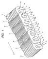
- Fig. 1 is a perspective view showing a main construction of a transmission chain (hereinafter, simply referred to as 'chain') for a chain type CVT according to the first embodiment of the invention.
- the chain 1 according to the first embodiment includes a plurality of sets, each of sets being composed of three kinds of link rows, that is, a first link row A, a second link row B, and a third link row C arranged in a chain proceeding direction (arrow G).
- the sets are combined into one unit.
- the link rows are connected to each other by pin members, the chain has an endless shape.
- the chain 1 has a threefold number of link rows.
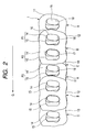
- Figs. 2 to 7 are front, rear, right side, left side, plan, and bottom views.
- the first, second, and third link rows A, B, and C each have a plurality of links 11, 12 and 13 arranged in the chain width direction.
- the link rows adjacent to each other in the chain proceeding direction are connected to each other by a pin member.
- a pin member P1 connects the first link row A and the second link row B
- another pin member P2 connects the second link row B and the third link row C
- another pin member P3 connects the third link row C and the next first link row A.
- the link rows A, B, and C are continuously connected to each other in the order of the link rows A, B, and C.
- the width direction of the chain is orthogonal to the chain proceeding direction.
- the width direction of the chain is parallel to the longitudinal direction of the pin members.
- the pin member connects the link rows adjacent to each other in the chain proceeding direction, and connects the links arranged parallel to the width direction of the chain in the same link row.
- the pin member is constituted by a pair of a pin 14 (first pin) and a strip 15 (second pin).
- the pin 14 and the strip 15 are all formed of metallic material such as bearing steel, in a rod shape.
- the strip 15 has a smaller length in the longitudinal direction of the pin than the pin 14.
- the links 11, 12, and 13 of each link row A, B, and C are formed of a rectangular flat member in which an external shape is composed of a gradual line.
- the links are substantially formed in the same shape.
- the links 11, 12 and 13 have the same thickness, and are formed of metallic material such as bearing steel.
- a first through hole 17 and a second through hole 18 are formed at a predetermined interval.
- the first through hole 17 is formed at a front side of each of the links 11, 12 and 13, and the second through hole 18 is formed at a back side thereof in the chain proceeding direction (arrow G direction).
- the first through hole 17 and the second through hole 18 have different shapes from each other, and a pair of the pin 14 and the strip 15 is inserted into both through holes 17 and 18- A pair of the pin 14 and the strip 15 passes the first through hole 17 of one link row and the second through hole 18 of another link row.
- the first link row A is connected with the second link row B by the pin 14 which is fixedly inserted into the second through hole 18 of the link 12 of the second link row B and rotatably inserted into the first through hole (not shown) of the link 11 of the first link row A, and the strip 15 which is rotatably inserted into the second through hole 18 of the link 12 of the second link row B and fixedly inserted into the first through hole (not shown) of the link 11 of the first link row A.
- the pair of the pin 14 and the strip 15 which are inserted into the same through hole relatively roll and move in contact with each other, so that the first link row A (link 11) and the second link row B (link 12) are flexibly connected to each other.
- Fig. 8 is a plan view schematically showing an arrangement of a plurality of links of the chain 1 according to the invention, which corresponds to Fig. 6-In the meantime, the pin member is omitted in the drawing, and the position of the pin member is indicated by a double-dotted line.
- the second link row B has an odd number of links 12
- the first link row A and the third link row C alternately arranged forward and backward in the chain proceeding direction of the second link row have an even number of links 11 and 13, respectively.
- the first link row A has eight links 11a to 11h
- the second link row B has nine links 12a to 12i
- the third link row C has eight links 13a to 13h.
- the link 11 is indicated by cross hatching
- the link 12 is indicated by single hatching at wide intervals
- the link 13 is indicated by single hatching at narrow intervals.
- intervals g1 between the two links 11 of the first link row A are equal, intervals g2 between the two links 12 of the second link row B are equal, intervals g3 between the two links 13 of the third link row C are equal, and the intervals g1, g2 and g3 are equal.
- This arrangement is also applied to other links 11 located at the other endmost in the chain width direction in the first link row A, such that two links 11g and 11h which are adjacent to each other and located at the other endmost interpose therebetween one link 13g of the third link row C and one link 12h of the second link row B.
- the third link row C two links 13a and 13b which are adjacent to each other and located at endmost in the chain width direction interpose therebetween one link 12b of the second link row B and one link 11b of the first link row A.
- This arrangement is also applied to other links 13 located at the other endmost in the chain width direction in the third link row C, such that two links 12g and 12h which are adjacent to each other and located at the other endmost interpose therebetween one link 12h of the second link row B and one link 11h of the first link row A.
- the third link row C only two links 11 and 12 having the same width exist between two links 13 adjacent to each other, so that the intervals g3 between the links 13 are equal.
- one link 11 of the first link row A, one link 12 of the second link row B, and one link 13 of the third link row C are continuously arranged in a repetitive order from one end to the other end in the chain width direction.
- one link 12 of the second link row B, one link 11 of the first link row A, and one link 13 of the next third link row C are arranged, and this order is regularly repeated until reaching the other end.
- the chain 1 is asymmetric with respect to the centerline c.
- the links 12 are symmetrically disposed with respect to the centerline c, but as for the first and third link rows A and C, the links are asymmetrically disposed.
- the chain 1 is asymmetric, the chain has an endless shape as a whole; therefore, the chain is saturated by moment that is generated from the asymmetry.
- the load in each of the sets composed of link rows A, B, and C, because intervals between two links adjacent to each other in the chain width direction of one link row are equal, when load is applied to the chain 1 in the chain proceeding direction, the load can be made equal within one link row.
- the first link row A and the third link row C has less links than the second link row B, load that is applied to one link is likely to increase.
- the intervals between the links are made equal, it is possible to prevent one link from being subject to a great load.
- each of the links is fatigued with rotation of the chain 1, so that the chain has better durability, and can stably transmit power for a long time.
- Fig. 9 is a perspective view showing a main construction of a transmission chain 100 for a chain type CVT according to a second embodiment of the invention.
- Fig. 10 is a front view showing the main construction of the transmission chain 100 according to the second embodiment.
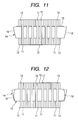
- Fig. 11 is a right side view showing the main construction of the transmission chain 100 according to the second embodiment.
- Fig. 12 is a left side view showing the main construction of the transmission chain 100 according to the second embodiment.
- Fig. 13 is a plan view showing the main construction of the transmission chain 100 according to the second embodiment.
- Fig. 14 is a bottom view showing the main construction of the transmission chain 100 according to the second embodiment.
- Fig. 15 is a plan view schematically showing an arrangement of a plurality of links according to the second embodiment.
- one link row has an arrangement in which two links which are adjacent to each other and located apart from the center part in the chain width direction of one link row interpose therebetween two links belonging to the other two link rows, respectively. All of the links of the link row A, B and C have an equal width, such that intervals g between two links interposing other two links therebetween are equal.
- This arrangement is also applied to other links 11 located at the other endmost in the chain width direction of the first link row A, such that two links 11h and 11g which are adjacent to each other and located at the other endmost interpose therebetween one link 13g of the third link row C and one link 12h of the second link row B.
- only two links having the same width are interposed between the two links which are adjacent to each other and located at endmost.
- the link 12e among the nine links 12 which is located at the center is disposed on the centerline c in the chain width direction.
- two links 12 adjacent to each other in the second link row B interpose therebetween two links 11 and 13 belonging to the first and third link rows A and C, respectively, so that, the intervals g between the two links adjacent to each other in the second link row B are equal.
- the third link row C apart from the center part in the chain width direction of the third link row C, that is, except for the two links 13d and 13e, two links which are adjacent to each other in the chain width direction interpose therebetween two links 11 and 12 belonging to the other two link rows A and B respectively.
- the two links 13d and 13e at the center part interpose therebetween two links 11d and 11e of the first link row A and one link 12e of the second link row B. Therefore, in the third link row C, the intervals g between two links, except for the two links 13d and 13e located at the center part, are equal.
- the whole arrangement of the links of the chain 100 will be described more fully.
- the first link row A, the second link row B, and the third link row C are symmetrically disposed with respect to the centerline c in the chain width direction. Therefore, since load applied to the transmission chain is made equal, it is possible to prevent moment from being generated due to the construction of the transmission chain.
- the intervals g between the links can be made small. Even when load is applied to end portions of the link rows A, B and C, the load can be divided into the link located at endmost in the chain width direction and the link closer to the center part. Therefore, it is prevented that a great load is applied to the link located at endmost. Particularly, because the first link row A and the third link row C has less links than the second link row B, load that is applied to one link is likely to increase. Thus, as the intervals g between the two links located at endmost in the chain width direction are made equal, it is possible to prevent one link from being subject to a great load.
- each of the links is fatigued with rotation of the chain 100, so that the chain has better durability, and can stably transmit power for a long time.
- the transmission chain according to the invention is not limited to the embodiment can be modified in various forms within the scope of the invention.
- the chain proceeding direction of the first link row A and the third link row C can be exchanged with respect to the second link row B.
- links 11d and 11e of the first link row A are disposed behind the link 12e in the chain proceeding direction.
- the links 11d and 11e of the first link row A may be disposed before the link 12e in the chain proceeding direction.
- the number of the link of the link rows A, B and C can be changed.
- Fig. 16 is a perspective view schematically showing a main construction of a chain type CVT (hereinafter, simply referred to 'CVT') of the transmission according to the embodiment of the invention.
- the CVT according to the embodiment is mounted in, an automobile, for example, and includes a metallic drive pulley 2 serving as a first pulley, a metallic driven pulley 3 serving as a second pulley, and the endless transmission chain 1 provided between the pulleys.
- the chain 1 of Fig. 16 shows a cross section of a part thereof.
- the drive pulley 2 is disposed at an input shaft 4 which is connected to the engine so as to rotate in conjunction with the input shaft 4, and includes a stationary sheave 6 having a conical sheave surface 6a, a movable sheave 7 having a conical sheave surface 7a facing the sheave surface 6a.
- a V-shaped groove is formed by the sheave surfaces 6a and 7a, and the sheave surfaces 6a and 7a forming the groove forcefully insert therebetween both ends of the pin member (first pin 14) of the chain 1, a frictional force generated between both of the end surfaces and the sheave surfaces transmits power between the first and second pulleys.
- the end surface of the pin member includes an end surface of the contact member.
- the driven pulley 3 is disposed to an output shaft 5 that is connected to a driving wheel so as to rotate in conjunction with the output shaft 5-Similar to the drive pulley 2, the driven pulley 3 includes a stationary sheave 8 and a movable sheave 9.
- the stationary sheave 8 and the movable sheave 9 have the sheave surfaces 8a and 9a, respectively, for forming the groove into which the chain 1 is forcefully inserted.
- a hydraulic actuator (not shown) is connected to the movable sheave 9 of the pulley 3, as similar to the case of the movable sheave 7 of the drive pulley 2, the width of the groove is changed by moving the movable sheave 9 during changing speed. Therefore, a winding radius of the chain 1 with respect to the output shaft 5 is changed.
- the chain 1 provided between the drive pulley 2 and the driven pulley 3 is the chain according to the invention. Since the detailed description about the chain is already described above, it will be omitted.
- the CVT according to the embodiment of the invention performs constantly variable transmission as follows.
- the width of the groove of the drive pulley 2 is increased by moving the movable sheave 7, so that a winding radius of the chain 1 with respect to an input shaft 11 is decreased.
- the width of the groove of the driven pulley 3 is decreased by moving the movable sheave 9, so that a winding radius of the chain 1 with respect to an output shaft 21 is increased. Therefore, the rotation speed of the output shaft 21 can be decreased.
- an opposite operation to the above-described operation is performed with respect to the drive pulley 2 and the driven pulley 3.
- the transmission according to the invention is not limited to the embodiment in which the width of the groove of both of the drive pulley and the driven pulley.
- the width of the groove of both of the drive pulley and the driven pulley can be changed, while the width of the other groove is fixed.
- the transmission may use a method of changing the width of the groove in a stepped manner or in a fixed manner or the like.
- the transmission chain according to the invention is not limited to the embodiment shown in the drawings, it can be modified in various forms without departing the scope of the invention, and it is possible to change the number of links belonging to the link rows A, B and C.
Landscapes
- Engineering & Computer Science (AREA)
- General Engineering & Computer Science (AREA)
- Mechanical Engineering (AREA)
- Transmissions By Endless Flexible Members (AREA)
- Electric Cable Arrangement Between Relatively Moving Parts (AREA)
Applications Claiming Priority (2)
| Application Number | Priority Date | Filing Date | Title |
|---|---|---|---|
| JP2005299917A JP2007107634A (ja) | 2005-10-14 | 2005-10-14 | 動力伝達チェーン及びそれを用いた動力伝達装置 |
| JP2005299918A JP2007107635A (ja) | 2005-10-14 | 2005-10-14 | 動力伝達チェーン及びそれを用いた動力伝達装置 |
Publications (2)
| Publication Number | Publication Date |
|---|---|
| EP1775497A2 true EP1775497A2 (fr) | 2007-04-18 |
| EP1775497A3 EP1775497A3 (fr) | 2007-10-24 |
Family
ID=37635741
Family Applications (1)
| Application Number | Title | Priority Date | Filing Date |
|---|---|---|---|
| EP06021567A Withdrawn EP1775497A3 (fr) | 2005-10-14 | 2006-10-13 | Chaine de transmission et transmission l'utilisant |
Country Status (2)
| Country | Link |
|---|---|
| US (1) | US20070087883A1 (fr) |
| EP (1) | EP1775497A3 (fr) |
Families Citing this family (3)
| Publication number | Priority date | Publication date | Assignee | Title |
|---|---|---|---|---|
| JP5136838B2 (ja) * | 2007-11-07 | 2013-02-06 | 株式会社ジェイテクト | 動力伝達チェーン |
| JP5152575B2 (ja) * | 2008-04-16 | 2013-02-27 | 株式会社ジェイテクト | 動力伝達チェーンおよびこれを備える動力伝達装置 |
| JP5839400B2 (ja) * | 2012-08-08 | 2016-01-06 | 株式会社椿本チエイン | サイレントチェーン |
Citations (1)
| Publication number | Priority date | Publication date | Assignee | Title |
|---|---|---|---|---|
| JPH02195045A (ja) | 1988-08-06 | 1990-08-01 | Reimers Getriebe Ag | 無段変速円錐板伝動装置用連結板チェーン |
Family Cites Families (5)
| Publication number | Priority date | Publication date | Assignee | Title |
|---|---|---|---|---|
| DE3324318A1 (de) * | 1983-07-06 | 1985-01-24 | P.I.V. Antrieb Werner Reimers GmbH & Co KG, 6380 Bad Homburg | Laschenkette fuer kegelscheibengetriebe |
| NL1000294C2 (nl) * | 1995-05-03 | 1996-11-05 | Gear Chain Ind Bv | Transmissieketting voor een kegeldrijfwerk. |
| DE19728181C1 (de) * | 1997-07-02 | 1999-01-28 | Piv Antrieb Reimers Kg Werner | Laschenkette für stufenlos verstellbare Kegelscheibengetriebe |
| KR20070005601A (ko) * | 2004-01-30 | 2007-01-10 | 가부시키가이샤 제이텍트 | 동력전달 체인 및 그 제조방법, 및 동력전달 장치 |
| NL1026773C2 (nl) * | 2004-08-03 | 2006-02-06 | Gear Chain Ind Bv | Scharniersamenstel voor een transmissieketting en transmissieketting voorzien van een dergelijk scharniersamenstel. |
-
2006
- 2006-10-13 US US11/580,242 patent/US20070087883A1/en not_active Abandoned
- 2006-10-13 EP EP06021567A patent/EP1775497A3/fr not_active Withdrawn
Patent Citations (1)
| Publication number | Priority date | Publication date | Assignee | Title |
|---|---|---|---|---|
| JPH02195045A (ja) | 1988-08-06 | 1990-08-01 | Reimers Getriebe Ag | 無段変速円錐板伝動装置用連結板チェーン |
Also Published As
| Publication number | Publication date |
|---|---|
| EP1775497A3 (fr) | 2007-10-24 |
| US20070087883A1 (en) | 2007-04-19 |
Similar Documents
| Publication | Publication Date | Title |
|---|---|---|
| EP1162387B1 (fr) | Courroie pour transmissions continues | |
| EP1837552A2 (fr) | Chaîne et système de transmission de puissance | |
| EP1754912B1 (fr) | Chaîne de transmission et dispositif de transmission | |
| US8038561B2 (en) | Power transmission chain, and power transmission system having the same | |
| EP1775497A2 (fr) | Chaine de transmission et transmission l'utilisant | |
| EP1788280A2 (fr) | Chaîne de transmission et dispositif de transmission l'utilisant | |
| US20070149332A1 (en) | Power transmission chain and power transmission device | |
| EP2116741A1 (fr) | Chaîne de transmission de puissance et dispositif de transmission de puissance ayant celle-ci | |
| JP2005299755A (ja) | 動力伝達チェーンおよびこれを備える動力伝達装置 | |
| JP4702626B2 (ja) | 動力伝達チェーンおよびこれを備える動力伝達装置 | |
| JP4423560B2 (ja) | 動力伝達チェーンおよびこれを備える動力伝達装置 | |
| JP2005233275A (ja) | 動力伝達チェーンおよび動力伝達装置 | |
| JP2006138452A (ja) | 動力伝達チェーンおよび動力伝達装置 | |
| JP4839716B2 (ja) | 動力伝達チェーンおよび動力伝達装置 | |
| JP4411532B2 (ja) | 動力伝達チェーンおよびこれを備える動力伝達装置 | |
| JP2007107635A (ja) | 動力伝達チェーン及びそれを用いた動力伝達装置 | |
| JP2005114133A (ja) | 動力伝達チェーン及びそれを用いた動力伝達装置 | |
| JP2006144976A (ja) | 動力伝達チェーンおよびこれを備える動力伝達装置 | |
| JP2007107634A (ja) | 動力伝達チェーン及びそれを用いた動力伝達装置 | |
| JP2005315341A (ja) | 動力伝達チェーンおよびこれを備える動力伝達装置 | |
| JP2005299756A (ja) | 動力伝達チェーンおよびこれを備える動力伝達装置 | |
| JP2006144855A (ja) | 動力伝達チェーンおよびこれを備える動力伝達装置 | |
| JP2007100737A (ja) | 動力伝達チェーン及びそれを用いた動力伝達装置 | |
| JP2006097856A (ja) | 動力伝達チェーンおよびこれを備える動力伝達装置 | |
| JP2007010050A (ja) | 動力伝達チェーンおよびこれを備える動力伝達装置 |
Legal Events
| Date | Code | Title | Description |
|---|---|---|---|
| PUAI | Public reference made under article 153(3) epc to a published international application that has entered the european phase |
Free format text: ORIGINAL CODE: 0009012 |
|
| AK | Designated contracting states |
Kind code of ref document: A2 Designated state(s): AT BE BG CH CY CZ DE DK EE ES FI FR GB GR HU IE IS IT LI LT LU LV MC NL PL PT RO SE SI SK TR |
|
| AX | Request for extension of the european patent |
Extension state: AL BA HR MK YU |
|
| PUAL | Search report despatched |
Free format text: ORIGINAL CODE: 0009013 |
|
| AK | Designated contracting states |
Kind code of ref document: A3 Designated state(s): AT BE BG CH CY CZ DE DK EE ES FI FR GB GR HU IE IS IT LI LT LU LV MC NL PL PT RO SE SI SK TR |
|
| AX | Request for extension of the european patent |
Extension state: AL BA HR MK YU |
|
| 17P | Request for examination filed |
Effective date: 20080423 |
|
| AKX | Designation fees paid |
Designated state(s): DE FR |
|
| STAA | Information on the status of an ep patent application or granted ep patent |
Free format text: STATUS: THE APPLICATION HAS BEEN WITHDRAWN |
|
| 18W | Application withdrawn |
Effective date: 20090616 |