EP1775554B1 - Dynamische primäre Fluganzeigen für aussergewöhnliche Lagebedingungen - Google Patents
Dynamische primäre Fluganzeigen für aussergewöhnliche Lagebedingungen Download PDFInfo
- Publication number
- EP1775554B1 EP1775554B1 EP06122069A EP06122069A EP1775554B1 EP 1775554 B1 EP1775554 B1 EP 1775554B1 EP 06122069 A EP06122069 A EP 06122069A EP 06122069 A EP06122069 A EP 06122069A EP 1775554 B1 EP1775554 B1 EP 1775554B1
- Authority
- EP
- European Patent Office
- Prior art keywords
- attitude
- fading
- display
- display format
- attitude angle
- Prior art date
- Legal status (The legal status is an assumption and is not a legal conclusion. Google has not performed a legal analysis and makes no representation as to the accuracy of the status listed.)
- Active
Links
Images


Classifications
-
- G—PHYSICS
- G01—MEASURING; TESTING
- G01C—MEASURING DISTANCES, LEVELS OR BEARINGS; SURVEYING; NAVIGATION; GYROSCOPIC INSTRUMENTS; PHOTOGRAMMETRY OR VIDEOGRAMMETRY
- G01C23/00—Combined instruments indicating more than one navigational value, e.g. for aircraft; Combined measuring devices for measuring two or more variables of movement, e.g. distance, speed or acceleration
Definitions
- the present invention generally relates to graphical display systems and, is particular, to dynamic flight displays.
- attitude refers generally to the position of an aircraft or spacecraft relative to the horizon or a celestial object, respectively.
- attitude refers to the angles for pitch, yaw and bank.
- attitude refers to the spacecraft's angular position and rotation. In both situations, it is essential to maintain and control proper attitude conditions.
- Unusual attitude conditions refer to situations where the craft is at an extreme angle or deviation. For example, in aircraft, such situations include having a high pitch angle or being banked at a high angle. When a craft is in an unusual attitude condition, it is important for the flight crew to correct and return the attitude to normal.
- the present invention addresses the problem of providing a display which minimizes distractions to a flight crew during unusual attitude conditions.
- the present invention comprises, a method of dynamically transitioning a display into a distinct display format during unusual attitude condition is provided.
- the method comprises collecting attitude data, comparing current attitude to a first set attitude angle, and fading a distinct display format into a display for unusual attitude conditions when current attitude is at least equal to the first set attitude angle.
- One embodiment comprises providing a graphical display system.
- the graphical display system comprises one or more sensors for collecting attitude data, a display element for displaying flight data, and at least one processor coupled to the one or more sensors and the display element for processing data collected by the one or more sensors.
- the at least one processor sends signals to the display element instructing the display element to fade in a distinct display format when a current attitude angle reaches a first set attitude angle.
- Another embodiment comprises, a computer readable medium having computer executable instructions for performing a method of dynamically transitioning into a distinct display format during unusual attitude conditions.
- the method comprises measuring at least one of a plurality of attitude angles, wherein the plurality of attitude angles define a craft's attitude, and comparing the at least one of a plurality of attitude angles to a corresponding first set attitude angle.
- the method also comprises sending a signal to a display element instructing the display element to gradually fade in a distinct display format once at least one of the plurality of attitude angles equals the corresponding first set attitude angle.
- a graphical display system comprises means for collecting attitude data, means for executing instructions for fading in a distinct display format when a current attitude angle reaches a first set attitude angle and means for displaying the distinct display format.
- Embodiments of the present invention aid flight crews in identifying when an aircraft is in unusual attitude conditions by transitioning to a distinct display format. Since direct outside views and current conformal visual image displays are not always effective means of aiding flight crews in identifying unusual attitude conditions, embodiments of the present invention give flight crews a great advantage over existing technology. In addition, distinct display formats in embodiments of the present invention aid flight crews in taking proper recovery actions by removing non-necessary data and providing necessary data in clear and intuitive formats. Finally, embodiments of the present invention enable these advantages while minimizing distraction and not startling flight crews as a distinct display format is transitioned into the display.
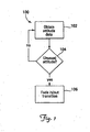
- Figure 1 is a flow chart showing a method of dynamically transitioning into a distinct display format according to one embodiment of the present invention.
- the distinct display format for unusual attitude conditions is distinct from a normal attitude display format used for normal attitude conditions.
- attitude data is collected. In aircraft, this includes data on the pitch, bank and yaw angles of the aircraft.
- the angles which define whether an aircraft is in an unusual attitude condition vary depending on the type of aircraft and flight conditions. For example, the pitch angles which define an unusual attitude condition in a Boeing 747 are not necessarily the same pitch angles which define an unusual attitude condition in a Cessna Skyhawk.
- the knowledge of how to determine appropriate angles defining unusual attitude conditions for different aircraft and flight conditions is known to one of skill in the art.
- the current aircraft attitude obtained from the attitude data is compared to a set attitude angle. If the current aircraft attitude angle is less than the set attitude angle, the process returns to 102 and updated current attitude data is collected. If the current aircraft attitude angle is equal to or greater than the set attitude angle, it is determined that the aircraft is entering unusual attitude conditions and the process continues at 106.
- the set angle varies depending on the type of craft, flight conditions, and attitude angle being analyzed, For example, in some embodiments, a set attitude angle for an aircraft is not the same as a set attitude angle for a helicopter. Additionally, in some embodiments, a set attitude angle for analyzing a bank angle is different than a set attitude angle for measuring pitch angle. Further, in some embodiments, a set attitude angle for measuring a positive pitch angle is not the same as a set attitude angle for measuring a negative pitch angle, where positive and negative is determined in relation to a zero-pitch reference line.
- a distinct display format is faded into the display.
- fading in a distinct display format includes fading out some graphics displayed on a normal attitude display format and fading in some graphics displayed on the distinct display format for unusual attitude conditions.
- fading in a distinct display format includes fading out perspective view graphics used on a normal attitude display format such as 3-dimensional terrain, runways, etc.
- fading in a distinct display format includes fading out flight symbols used on a normal attitude display format, but which are not necessary in a distinct display format for unusual attitude conditions. In such embodiments, the determination of what flight symbols are non-necessary and should be faded out depends on the aircraft and flight conditions.
- these non-necessary flight symbols include flight path markers and speed deviation tapes.
- other flight symbols are non-necessary and faded out.
- fading in a distinct display format includes gradually moving and aligning the horizon line on the display with the zero-pitch reference line. The two reference lines are maintained together while the aircraft is in unusual attitude conditions. Such embodiments further aid flight crews by alleviating possible confusion when the zero-pitch line and the horizon line are not at the same position.
- fading in a distinct display format includes fading in a two color overlay wherein the color above a zero-pitch reference line is different from the color below the zero-pitch reference line.
- fading in a distinct display format also includes gradually changing the size of flight symbology relevant to attitude correction.
- pitch chevrons will gradually grow and decrease in size as the pitch angle increases and decreases, respectively.
- the zero-pitch line gradually increases in size.
- other flight symbology relevant to attitude correction gradually changes size.
- fading in a distinct display format includes gradually changing the color of flight symbology to aid flight crews during unusual attitude conditions.
- a distinct display format and a normal attitude display format are displayed substantially simultaneously with varied degrees of prominence based on the craft attitude angle.
- a distinct display format and a normal attitude display format are displayed substantially independently from one another. That is, display of one format does not occur until the other has substantially faded from the display.
- Figs. 2 and 3 describe exemplary embodiments of methods showing when to start fading and how to fade in a distinct display format
- Figs. 6 and 8 are images of exemplary embodiments showing distinct display formats as described above with respect to Fig. 1 .
- FIG. 2 is a flow chart showing another method of dynamically transitioning into a distinct display format according to one embodiment of the present invention.
- attitude data is collected from sensors, such as inertial gyroscopes, which measure attitude angles.
- the current aircraft attitude obtained from the attitude data is compared to a set attitude angle for each attitude angle measured (i.e. pitch angle, yaw angle, and bank angle). If current aircraft attitude is less than a set attitude angle corresponding to the attitude angle being measured, the process returns to 202 and updated current attitude data is collected. If a current aircraft attitude angle is greater than the corresponding set attitude angle, it is determined that the aircraft is entering unusual attitude conditions and the process continues at 206.
- the set angle varies depending on the type of craft, flight conditions, and attitude angle being analyzed.
- a set attitude angle for an aircraft is not the same as a set attitude angle for a helicopter.
- a set attitude angle for analyzing a bank angle is different than a set attitude angle for measuring pitch angle.
- a set attitude angle for measuring a positive pitch angle is not the same as a set attitude angle for measuring a negative pitch angle, where positive and negative is determined in relation to a zero-pitch reference line.
- a distinct display format transitions into the display by gradually fading in as discussed above with regards to Fig. 1 .
- the transition occurs at a substantially uniform rate over a set period of time. In some embodiments, the set period of time is 3 seconds. In other embodiments, the transition or fade rate is a rate based on the rate at which the craft attitude angle deviates from the set attitude angle.
- attitude data is again collected.
- the attitude data is analyzed to determine if the attitude has returned to normal. If the attitude continues to be unusual, the process returns to 208 to collect updated attitude condition data. This process continues until the data indicates, at 210, that attitude conditions have been returned to normal.
- the distinct display format is faded out and the display returns to the normal attitude display format for normal flight conditions at 212.
- fading out the distinct display format includes fading in perspective view graphics, such as 3-dmiensional terrain, and other flight symbols that were faded out at 206.
- fading out the distinct display format includes fixing a zem-pitch reference line at a selected position during the process of fading the distinct display format out of the display. The process ends at 214.
- FIG. 3 is a flow chart showing another method of dynamically transitioning into a distinct display format according to one embodiment of the present invention.
- attitude data is collected from sensors, such as inertial gyroscopes, which measure attitude angles.
- the data is analyzed to determine if an aircraft attitude angle has reached a first set angle corresponding to the aircraft attitude angle being measured. In other words, at least one of the attitude angles is compared to a corresponding first set angle. The first set angle varies depending on the type of craft, flight conditions, and attitude angle being analyzed. If the result of the analysis at 304 is that an aircraft attitude angle has not reached a first set angle, the process returns to 302 and updated current attitude data is collected. If the result of the analysis at 304 is that an aircraft attitude angle has reached a first set angle, the process continues at 306.
- a transition begins gradually fading in a distinct display format as described above with regards to Fig. 1 .
- This includes fading out perspective view graphics such as 3-dimensional terrain, aligning the horizon line on the display with the zero-pitch reference line, and changing the size of flight symbology relevant to attitude correction. These transitions do not occur abruptly, but rather they occur gradually as the display is faded in.
- the rate of transition or fading is based on a continuous function of the rate of attitude change between the first set attitude angle and a second set attitude angle.
- the percentage of fading depends on the attitude angle of the craft between the first and second set attitude angles such that the first set attitude angle corresponds substantially to 100 percent display of a normal attitude display format and the second set attitude angle corresponds substantially to 100 percent display of a distinct display format.
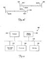
- the rate of transition or fade is based on an incremental change between the first set angle and a second set angle corresponding to the aircraft attitude angle being measured, as shown in Fig. 3B .
- the number of degrees between first set angle 320 and second set angle 324 are divided into N increments 322-1 ... 322-N.
- the N increments are substantially equally spaced.
- the N increments are spaced at varying sizes.
- Each of increments 322-1... 322-N is assigned a percentage of fading the distinct display format. The percentage of fading is correlated to a percentage of transparency/opacity.
- 322-1 is assigned 2% fading
- 322-2 is assigned 4% fading
- 322-3 is assigned 6% fading and so on to 322-N which is assigned 100% fading.
- 322-1 corresponds to 2% transparency of such graphics
- 322-2 corresponds to 4% transparency, and so on.
- 322-1 corresponds to 2% opacity
- 322-2 corresponds to 4% opacity, and so on.
- first set angle 320 is 52° and second set angle 324 is 55° when measuring bank; whereas, first set angle 320 is 29° and second set angle 324 is 32° when measuring positive pitch angle.
- set pitch angles are different when measuring negative pitch angles than when measuring positive pitch angles.
- each of increments 322-1 ... 322-N correspond to a percentage change in size.
- the percentage change in size is not necessarily the same as the percentage of fading.
- 322-1 corresponds to 2% fading but, it corresponds to 10% increase in normal size.
- size change is not limited to 100% increase in size. Therefore, in some embodiments, size can continue to change beyond reaching second set angle 324 based on similarly spaced continuing increments beyond second set angle 324. Hence, the change in size is based on attitude measurements taken during unusual attitude conditions.
- each of increments 322-1...322-N correspond to a percentage change in color.
- the percentage change in color is not necessarily the same as the percentage of fading.
- 322-1 corresponds to 2% fading but, it corresponds to 10% color change.
- color change is not limited to 100%. Therefore, in some embodiments, color can continue to change beyond reaching second set angle 324 based on continuing increments beyond second set angle 324.
- the rate of fading in a distinct display format is based on a continuous function of a rate of attitude change between a first set attitude angle and a second set attitude angle while the rate of fading out a distinct display format is based on a continuous function of a rate of attitude change between a third set attitude angle and a fourth set attitude angle.
- the percentage of fading in the distinct display format depends on the attitude angle of the craft between the first and second set attitude angles such that the second set attitude angle corresponds substantially to 100 percent display of the distinct display format.
- the percentage of fading out the distinct display format depends on the attitude angle of the craft between the third and fourth set attitude angles such that the fourth set attitude angle corresponds substantially to 100 percent display of the normal attitude display format.
- the rate of fading in a distinct display format is based on an incremental change between a first set attitude angle and a second set attitude angle while the rate of fading out a distinct display format is based on an incremental change between a third set attitude angle and a fourth set attitude angle as shown in Fig. 3C .
- the number of degrees between first set angle 330 and second set angle 334 are divided into N substantially equally spaced increments 332-1 ... 332-N.
- Each of increments 332-1 ... 332-N is assigned a percentage of fading in the distinct display format The percentage of fading in is correlated to a percentage of transparency/opacity as described above with regards to Fig, 3B .
- the number of degrees between third set angle 340 and fourth set angle 344 are divided into M substantially equally spaced increments 342-1... 342-M.
- Each of increments 342-1 ... 342-M is assigned a percentage of fading out the distinct display format. The percentage of fading out is correlated to a percentage of transparency/opacity as described in relation to Fig. 3B .
- the range of degrees from third set angle 340 to fourth set angle 344 overlaps the range from first set angle 330 to second set angle 334.
- the ranges do not overlap.
- fading in a distinct display format is triggered when attitude of the aircraft reaches first set angle 330 and finishes fading in when attitude reaches second set angle 334; whereas, fading out a distinct display format is triggered when attitude reaches third set angle 340 and finishes fading out when attitude reaches fourth set angle 344.
- Overlapping the ranges avoids causing a distinct display to flash which occurs when starting both fading in and out at the same set angle.
- the set angles and respective ranges vary with aircraft type, flying conditions, and angle being measured.
- first set angle 330 is 52°
- second set angle 334 is 55°
- third set angle 340 is 53°
- fourth set angle 344 is 50° when measuring bank
- first set angle 330 is 29°
- second set angle 334 is 32°
- third set angle 340 is 30°
- fourth set angle 344 is 27° when measuring positive pitch angle.
- set pitch angles are different when measuring negative pitch angles than when measuring positive pitch angles.
- transition (i.e. fading) of a distinct display format begins at 306, current attitude data is obtained at 308.
- a check is performed to determine if attitude has changed since the previous measurement of attitude. If attitude has not changed, the process returns to 308 where current updated attitude data is obtained. If attitude has changed, the amount of fading in/out a distinct display format changes accordingly as described above with respect to Figs. 3B and 3C .
- it is determined if attitude angles have returned to normal attitude angles. If they have not, the process returns to 308. If attitude angles have returned to normal attitude angles, the process ends at 316. In some embodiments, fading out a distinct display format is delayed a set period of time after returning to normal attitude angles.
- fading out a distinct display format is delayed when an aircraft has been in a roll with angles over 65°. In some embodiments, the delay is set at 6 seconds. The delay prevents confusion which might result from repeated fading in/out of a distinct display format if the aircraft alternates between unusual and normal attitude conditions in quick succession.
- FIG. 4 is a block diagram of a graphical display system which dynamically transitions into a distinct display format during unusual attitude conditions according to one embodiment of the present invention.
- an exemplary graphical display system 400 includes processor 404 configured to provide data to display element 408 for display.
- One or more data sources are coupled to processor 404 via bus 410. These data sources include, but are not limited to, sensors 402, user input element 412 and memory 406. In some embodiments, one or more of these data sources are omitted.
- sensors 402 are used to provide attitude data to processor 404 for use by processor 404 in determining when to fade out perspective view graphics and fade in a distinct unusual attitude display.
- Sensors 402 include, but are not limited to, gyroscopes, accelerometers, magnetometers, global positioning system (GPS) receivers, etc.
- GPS global positioning system
- User input element 412 includes, but is not limited to, keyboards, touch screens, microphones, etc. In some embodiments, user input element 412 comprises more than one type of input element. In other embodiments, display system 400 does not include user input element 412, User input element 412 is used to provide user feedback to display system 400. Such feedback includes, but is not limited to, a pilot override preventing the fading in of a distinct display format.
- Memory 406 includes any type of suitable medium such as floppy disks, conventional hard disks, CD-ROM, flash memory ROM, nonvolatile ROM, RAM, or other suitable medium, Processor 404 and memory 406 are coupled together allowing processor 404 to write to and store data in memory 406 as well as retrieve stored data from memory 406.
- memory 406 stores data received by processor 404 from sensors 402.
- memory 406 temporarily stores data to be transmitted from processor 404 to display element 408.
- memory 406 is used to store a database of graphics for retrieval by processor 404 and display on display element 408,
- memory 406 is used to store analysis result data calculated by processor 404, such as a rate of attitude transition.
- Processor 404 includes or interfaces with hardware components that support the graphics display system.
- these hardware components include one or more microprocessors, graphics processors, memories, storage devices, interface cards, and other standard components known in the art.
- processor 404 includes or functions with software programs, firmware or computer readable instructions for carrying out various methods, process tasks, calculations, control functions, and the generation of display signals and other data used in the operation of the display system.
- These instructions are typically stored on any appropriate medium used for storage of computer readable instructions such as floppy disks, conventional hard disks, CD-ROM, flash ROM, nonvolatile ROM, RAM, and other like medium. In some embodiments, these instructions are stored on memory 406.
- Display element 408 includes any display element suitable for displaying the various symbols and information for the operation of embodiments of the present invention. There are many known display elements that are suitable for this task, such as various CRT, active matrix LCD and passive matrix LCD display systems.
- Processor 404 sends appropriate signals and data to display element 408. These signals and data instruct display element 408 which graphics to display and include instructions for fading out perspective view graphics and fading in a distinct unusual attitude display necessary for the operation of embodiments of the present invention.
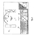
- Figure 5 is an image of a graphical display during flight according to one embodiment of the present invention.
- Fig. 5 includes sky 502, terrain 504, zero-pitch reference line 506, and flight symbology 508.
- Figure 6 is an image of a graphical display with a distinct display format for unusual attitude conditions according to one embodiment of the present invention.
- the embodiment in Fig. 6 includes sky 502 and terrain 504.
- terrain 504 is faded out.
- the portion of sky 502 below zero-pitch reference line 506 has faded in or darkened gradually which aids the flight crew in locating and distinguishing zero-pitch reference line 506.
- zero-pitch reference line 506 has changed appearance to indicate unusual attitude conditions.
- zero-pitch reference line 506 has changed from a solid white line in Fig. 5 to a dotted white line in Fig. 6 .
- pitch chevron 610 has faded into the display in Fig. 5 . The changes do not occur abruptly but gradually, as described in relation to Figs. 1-3C , so as not to distract or startle a flight crew.
- Figure 7 is an image of a graphical display during flight according to one embodiment of the present invention.
- Fig. 7 includes sky 702, terrain 704, zero-pitch reference line 706, and flight symbology 708 and 710.
- Figure 8 is an image of a graphical display with a distinct display format for unusual attitude conditions according to one embodiment of the present invention, As shown, the embodiment in Fig. 8 includes sky 702. However, sky 702 has changed to a darker more intense color as shown. Terrain 704 has faded out and been replaced by flat background 804. In some embodiments, flat background is brown. In other embodiments, other colors are used. Additionally, flight symbology 710 has faded out. Flight symbology 708 remains and warning 802 has faded in. Warning 802 serves as an additional indicator to flight crews of unusual attitude conditions. The changes from Fig. 7 to Fig. 8 occur gradually as described above with regards to Figs. 1-3C .
Landscapes
- Engineering & Computer Science (AREA)
- Radar, Positioning & Navigation (AREA)
- Remote Sensing (AREA)
- Aviation & Aerospace Engineering (AREA)
- Physics & Mathematics (AREA)
- General Physics & Mathematics (AREA)
- Controls And Circuits For Display Device (AREA)
- Navigation (AREA)
Claims (10)
- Verfahren zum dynamischen Überführen einer Anzeige in ein distinktes Anzeigeformat während außergewöhnlicher Lagebedingungen, wobei das Verfahren die folgenden Schritte umfasst:Sammeln von Lagedaten;Vergleichen der aktuellen Lage mit einem ersten eingestellten Lagewinkel; undBeginnen eines Übergangs, gekennzeichnet durch alle folgenden Schritte:Überblenden eines distinkten Anzeigeformats in eine Anzeige für außergewöhnliche Lagebedingungen, wenn die aktuelle Lage mindestens gleich dem ersten eingestellten Lagewinkel ist;Ausblenden von dreidimensionalen perspektivischen Ansichtsgrafiken;Ausrichten einer Horizontlinie auf der Anzeige mit der Null-Neigungs-Referenzlinie undÄndern der Größe von für Lagekorrektur relevanter Flugsymbologie.
- Verfahren nach Anspruch 1, wobei das Überblenden eines distinkten Anzeigeformats in eine Anzeige einen der folgenden Schritte umfasst:im Wesentlichen gleichzeitiges Anzeigen des distinkten Anzeigeformats und eines Normallage-Anzeigeformats mit unterschiedlichen Hervorhebungsgraden auf der Anzeige auf der Basis des Fahrzeug-Lagewinkels; undAnzeigen des distinkten Anzeigeformats im Wesentlichen unabhängig von der Anzeige des Normallage-Anzeigeformats.
- Verfahren nach Anspruch 1, wobei das Überblenden eines distinkten Anzeigeformats auf eine Anzeige einen der folgenden Schritte umfasst:Überblenden eines distinkten Anzeigeformats auf eine Anzeige mit einer im Wesentlichen gleichförmigen Rate über einen eingestellten Zeitraum; undÜberblenden eines distinkten Anzeigeformats auf eine Anzeige mit einer Rate auf der Basis der Rate, mit der der Fahrzeug-Lagewinkel von dem ersten eingestellten Lagewinkel abweicht.
- Verfahren nach Anspruch 1, wobei das Überblenden eines distinkten Anzeigeformats in eine Anzeige einen oder mehrere der folgenden Schritte umfasst:Ändern des Aussehens einer Null-Neigungs-Referenzlinie; undEinblenden einer zweifarbigen Überlagerung, wobei die Farbe über einer Null-Neigungs-Referenzlinie von der Farbe unter der Null-Neigungs-Referenzlinie verschieden ist.
- Verfahren nach Anspruch 1, wobei das Überblenden eines distinkten Anzeigeformats auf eine Anzeige Folgendes umfasst:Aufteilen der Anzahl von Graden zwischen dem ersten eingestellten Lagewinkel und einem zweiten eingestellten Lagewinkel in N Inkremente;Vergeben jedes von N Inkrementen an einen Prozentsatz des Blendens; undEinblenden des distinkten Anzeigeformats um den vergebenen Prozentsatz des Blendens, während die aktuelle Lage jedes von N Inkrementen erreicht, dergestalt, dass, wenn die aktuelle Lage die zweite eingestellte Lage erreicht, das Überblenden des distinkten Anzeigeformats in die Anzeige im Wesentlichen beendet ist, und wenn die aktuelle Lage zu der ersten eingestellten Lage zurückkehrt, das Ausblenden des distinkten Anzeigeformats aus der Anzeige im Wesentlichen beendet ist.
- Verfahren nach Anspruch 1, wobei das Überblenden eines distinkten Anzeigeformats auf eine Anzeige Folgendes umfasst:Aufteilen der Anzahl von Graden zwischen dem ersten eingestellten Lagewinkel und einem zweiten eingestellten Lagewinkel in N Inkremente;Aufteilen der Anzahl von Graden zwischen einem dritten eingestellten Lagewinkel und einem vierten eingestellten Lagewinkel in M Inkremente;Vergeben jedes von N Inkrementen an einen Prozentsatz des Überblendens des distinkten Anzeigeformats in die Anzeige;Vergeben jedes von M Inkrementen an einen Prozentsatz des Ausblendens des distinkten Anzeigeformats aus der Anzeige;Einblenden des distinkten Anzeigeformats um den vergebenen Prozentsatz des Blendens, während die aktuelle Lage jedes von N Inkrementen erreicht; undAusblenden des distinkten Anzeigeformats um den vergebenen Prozentsatz des Blendens, während die aktuelle Lage zu jedem von M Inkrementen zurückkehrt.
- Verfahren nach Anspruch 1, wobei das Überblenden eines distinkten Anzeigeformats auf eine Anzeige einen der folgenden Schritte umfasst:Einblenden des distinkten Anzeigeformats als stetige Funktion des Fahrzeug-Lagewinkels zwischen einem ersten eingestellten Lagewinkel und einem zweiten eingestellten Lagewinkel dergestalt, dass der erste eingestellte Lagewinkel im Wesentlichen 100% Anzeige eines Normallage-Anzeigeformats entspricht und der zweite eingestellte Lagewinkel im Wesentlichen 100% Anzeige des distinkten Anzeigeformats entspricht; undEinblenden des distinkten Anzeigeformats als stetige Funktion des Fahrzeug-Lagewinkels zwischen einem ersten eingestellten Lagewinkel und einem zweiten eingestellten Lagewinkel und Ausblenden des distinkten Anzeigeformats als stetige Funktion des Fahrzeug-Lagewinkels zwischen einem dritten eingestellten Lagewinkel und einem vierten eingestellten Lagewinkel dergestalt, dass der zweite eingestellte Lagewinkel im Wesentlichen 100% Anzeige des distinkten Anzeigeformats entspricht und der vierte eingestellte Lagewinkel im Wesentlichen 100% Anzeige eines Normallage-Anzeigeformats entspricht.
- Verfahren nach Anspruch 7, wobei das Ausblenden des distinkten Anzeigeformats als stetige Funktion des Fahrzeug-Lagewinkels zwischen einem dritten eingestellten Lagewinkel und einem vierten eingestellten Lagewinkel Folgendes umfasst:Einstellen des dritten Lagewinkels dergestalt, dass Geländemerkmale perspektivischer Ansicht im Wesentlichen bei dem dritten Lagewinkel aus der Anzeige ausgeblendet werden; undSetzen des vierten Lagewinkels dergestalt, dass Geländemerkmale perspektivischer Ansicht im Wesentlichen bei dem vierten Lagewinkel die gesamte Anzeige bedecken.
- Verfahren nach Anspruch 1, ferner mit dem folgenden Schritt: Ausblenden eines distinkten Anzeigeformats aus der Anzeige, sobald die Lage zu Normal zurückkehrt.
- Verfahren nach Anspruch 9, wobei das Ausblenden eines distinkten Anzeigeformats aus der Anzeige einen der folgenden Schritte umfasst:Verzögerung um einen Zeitraum nachdem sich die Lage nicht mehr in außergewöhnlichen Lagebedingungen befindet, vor dem Ausblenden eines distinkten Anzeigeformats aus der Anzeige; undFixieren einer Null-Neigungs-Referenzlinie an einer gewählten Position während des Vorgangs des Ausblendens eines distinkten Anzeigeformats aus der Anzeige.
Applications Claiming Priority (1)
| Application Number | Priority Date | Filing Date | Title |
|---|---|---|---|
| US11/250,124 US7403133B2 (en) | 2005-10-13 | 2005-10-13 | Dynamic primary flight displays for unusual attitude conditions |
Publications (3)
| Publication Number | Publication Date |
|---|---|
| EP1775554A2 EP1775554A2 (de) | 2007-04-18 |
| EP1775554A3 EP1775554A3 (de) | 2008-03-12 |
| EP1775554B1 true EP1775554B1 (de) | 2011-04-20 |
Family
ID=37643577
Family Applications (1)
| Application Number | Title | Priority Date | Filing Date |
|---|---|---|---|
| EP06122069A Active EP1775554B1 (de) | 2005-10-13 | 2006-10-11 | Dynamische primäre Fluganzeigen für aussergewöhnliche Lagebedingungen |
Country Status (3)
| Country | Link |
|---|---|
| US (1) | US7403133B2 (de) |
| EP (1) | EP1775554B1 (de) |
| DE (1) | DE602006021378D1 (de) |
Families Citing this family (28)
| Publication number | Priority date | Publication date | Assignee | Title |
|---|---|---|---|---|
| US7432828B2 (en) * | 2006-02-14 | 2008-10-07 | Honeywell International Inc. | Dynamic lateral deviation display |
| US7724155B1 (en) * | 2006-09-07 | 2010-05-25 | Rockwell Collins, Inc. | Graphical methods for enhancing attitude awareness |
| US9091545B2 (en) * | 2007-11-27 | 2015-07-28 | Florida Institute For Human And Machine Cognition, Inc. | Motion-resolving hover display |
| US8339284B2 (en) * | 2008-03-11 | 2012-12-25 | Honeywell International Inc. | Method and apparatus for displaying flight path information in rotocraft |
| US8063798B2 (en) * | 2008-06-03 | 2011-11-22 | Honeywell International Inc. | Methods and apparatus to assist pilots under conditions in which spatial disorientation may be present |
| USD601570S1 (en) * | 2008-11-05 | 2009-10-06 | Dassault Systemes | Image for a portion of a display screen |
| US20100161158A1 (en) * | 2008-12-18 | 2010-06-24 | Honeywell International Inc. | Systems and methods for enhancing terrain elevation awareness |
| DE102009006830A1 (de) * | 2009-01-30 | 2010-08-19 | Astrium Gmbh | Vorrichtung zur Übermittlung von Information betreffend einen Betriebszustand eines Fahrzeugs |
| US8209122B2 (en) * | 2009-03-27 | 2012-06-26 | Honeywell International Inc. | System and method for rendering visible features of a target location on a synthetic flight display |
| US8406466B2 (en) * | 2009-12-14 | 2013-03-26 | Honeywell International Inc. | Converting aircraft enhanced vision system video to simulated real time video |
| US8140260B2 (en) * | 2010-02-12 | 2012-03-20 | Honeywell International Inc. | System for enhancing a vehicle operator's orientation and ability to navigate |
| US9261883B2 (en) * | 2010-05-07 | 2016-02-16 | Honeywell International Inc. | Systems and methods for performing excessive negative pitch alert and for biasing a sink rate alert |
| US8699781B1 (en) | 2010-06-14 | 2014-04-15 | Rockwell Collins, Inc. | Embedded symbology for use with scene imaging system |
| JP5916283B2 (ja) * | 2010-07-01 | 2016-05-11 | 三菱重工業株式会社 | 表示装置、操縦支援システム、及び表示方法 |
| US9494447B2 (en) * | 2010-07-28 | 2016-11-15 | Honeywell International Inc. | Methods and systems for attitude differentiation in enhanced vision images |
| US8767013B2 (en) * | 2011-12-07 | 2014-07-01 | Honeywell International Inc. | System and method for rendering a sky veil on a vehicle display |
| US9347793B2 (en) * | 2012-04-02 | 2016-05-24 | Honeywell International Inc. | Synthetic vision systems and methods for displaying detached objects |
| JP2014053794A (ja) * | 2012-09-07 | 2014-03-20 | Nintendo Co Ltd | 情報処理プログラム、情報処理装置、情報処理システム及び情報処理方法 |
| US9390559B2 (en) | 2013-03-12 | 2016-07-12 | Honeywell International Inc. | Aircraft flight deck displays and systems and methods for enhanced display of obstacles in a combined vision display |
| EP3018571B1 (de) * | 2014-11-06 | 2021-03-10 | Airbus Defence and Space | Auswahleinheit zur Auswahl oder Steuerung verschiedener Zustände oder Funktionen eines Flugzeugsystems |
| EP3271743A4 (de) * | 2015-03-17 | 2018-12-05 | Sikorsky Aircraft Corporation | Bahnregler eines fahrzeugs |
| US9540116B1 (en) * | 2015-06-30 | 2017-01-10 | Rockwell Collins, Inc. | Attitude indicator generating and presenting system, device, and method |
| US9969503B2 (en) * | 2016-07-21 | 2018-05-15 | Rockwell Collins, Inc. | Head-up display (HUD) stall recovery symbology |
| FR3054686B1 (fr) * | 2016-07-28 | 2018-08-03 | Thales | Procede de gestion graphique de la symbologie dans une vue synthetique tridimensionnellle du paysage exterieur dans un systeme de visualisation de bord pour aeronef |
| US11037454B2 (en) * | 2016-11-03 | 2021-06-15 | The Boeing Company | Automatic braking system controller |
| EP3339809A1 (de) * | 2016-12-22 | 2018-06-27 | Ecole Nationale de l'Aviation Civile | Verfahren und vorrichtung zur steuerung der anzeige einer fahrzeugausrichtung |
| US10883851B2 (en) * | 2018-09-17 | 2021-01-05 | Honeywell International Inc. | Systems and methods for dynamic readouts for primary flight displays |
| US11908329B2 (en) | 2021-03-25 | 2024-02-20 | Rockwell Collins, Inc. | Unusual attitude recovery symbology |
Family Cites Families (54)
| Publication number | Priority date | Publication date | Assignee | Title |
|---|---|---|---|---|
| US4090189A (en) | 1976-05-20 | 1978-05-16 | General Electric Company | Brightness control circuit for LED displays |
| US4241294A (en) | 1979-05-23 | 1980-12-23 | General Electric Company | Brightness control circuit for a vacuum fluorescent display |
| JPS5837484B2 (ja) | 1979-09-25 | 1983-08-16 | 日産自動車株式会社 | 自動車用電子メ−タの輝度制御装置 |
| GB2213019B (en) | 1980-08-19 | 1989-10-25 | Elliott Brothers London Ltd | Head-up display systems |
| US4514727A (en) | 1982-06-28 | 1985-04-30 | Trw Inc. | Automatic brightness control apparatus |
| EP0340485B1 (de) | 1988-04-12 | 1996-07-10 | Kansei Corporation | Steuerungssystem für Headup-Displays für Kraftfahrzeuge |
| US5201032A (en) | 1988-06-02 | 1993-04-06 | Ricoh Company, Ltd. | Method and apparatus for generating multi-level character |
| US5426727A (en) | 1989-01-20 | 1995-06-20 | Asahi Kogaku Kogyo K.K. | High-quality character generating system and method for use therein |
| US5198812A (en) * | 1992-03-04 | 1993-03-30 | The United States Of America As Represented By The Secretary Of The Air Force | Aircraft attitude indicator display |
| US5343395A (en) | 1992-08-26 | 1994-08-30 | Watts Alan B | Aircraft landing guidance system and method |
| US5486821A (en) | 1994-05-26 | 1996-01-23 | The United States Of America As Represented By The Secretary Of The Navy | Artificial horizon altitude warning system |
| US5757127A (en) | 1994-06-10 | 1998-05-26 | Nippondenso Co., Ltd. | Transparent thin-film EL display apparatus with ambient light adaptation means |
| US5745863A (en) | 1995-09-22 | 1998-04-28 | Honeywell Inc. | Three dimensional lateral displacement display symbology which is conformal to the earth |
| US5745095A (en) | 1995-12-13 | 1998-04-28 | Microsoft Corporation | Compositing digital information on a display screen based on screen descriptor |
| US5747863A (en) | 1996-07-08 | 1998-05-05 | Nikon Corporation | Infrared solid-state image pickup device and infrared solid-state image pickup apparatus equipped with this device |
| US6057856A (en) | 1996-09-30 | 2000-05-02 | Sony Corporation | 3D virtual reality multi-user interaction with superimposed positional information display for each user |
| JP4007633B2 (ja) | 1996-10-09 | 2007-11-14 | 株式会社島津製作所 | ヘッドアップディスプレイ |
| US5838262A (en) | 1996-12-19 | 1998-11-17 | Sikorsky Aircraft Corporation | Aircraft virtual image display system and method for providing a real-time perspective threat coverage display |
| JPH10319896A (ja) | 1997-05-15 | 1998-12-04 | Sony Corp | 情報表示装置、ならびにその表示状態検出方法、表示状態調整方法、および保守管理方法 |
| FR2765023B1 (fr) | 1997-06-20 | 1999-09-17 | Sextant Avionique | Procede et dispositif de polarisation d'un ecran lcd en fonction de l'eclairage ambiant |
| US6292305B1 (en) | 1997-08-25 | 2001-09-18 | Ricoh Company, Ltd. | Virtual screen display device |
| US6166744A (en) | 1997-11-26 | 2000-12-26 | Pathfinder Systems, Inc. | System for combining virtual images with real-world scenes |
| US6690299B1 (en) | 1998-01-12 | 2004-02-10 | Rockwell Collins, Inc. | Primary flight display with tactical 3-D display including three view slices |
| DE19816647C2 (de) | 1998-04-15 | 2000-12-14 | Daimler Chrysler Ag | Vorrichtung zur Verbesserung des Kontrastes in einem Head-Up-Display in einem Kraftfahrzeug |
| DE19822017A1 (de) | 1998-05-15 | 1999-12-16 | Deep Blue Technology Ag Lenzbu | Vorrichtung zur Erzeugung eines Warnsignals, insbesondere für Helikopter |
| US6629630B2 (en) * | 1998-06-19 | 2003-10-07 | Scimed Life Systems, Inc. | Non-circular resection device and endoscope |
| JP4052741B2 (ja) | 1998-09-30 | 2008-02-27 | セントラル硝子株式会社 | 反射型ディスプレイ用積層ガラス |
| US6567014B1 (en) * | 1998-11-05 | 2003-05-20 | Rockwell Collins, Inc. | Aircraft head up display system |
| US6208933B1 (en) | 1998-12-04 | 2001-03-27 | Northrop Grumman Corporation | Cartographic overlay on sensor video |
| US6744478B1 (en) | 1998-12-28 | 2004-06-01 | Central Glass Company, Limited | Heads-up display system with optical rotation layers |
| US6690296B2 (en) | 1998-12-31 | 2004-02-10 | Honeywell Inc. | Airborne alerting system |
| US7411519B1 (en) | 1999-05-14 | 2008-08-12 | Honeywell International Inc. | System and method for predicting and displaying wake vortex turbulence |
| US6226007B1 (en) | 1999-05-21 | 2001-05-01 | Sun Microsystems, Inc. | Method and apparatus for modeling specular reflection |
| JP2001106417A (ja) | 1999-10-05 | 2001-04-17 | Oki Data Corp | 画像形成装置 |
| US6570581B1 (en) | 1999-10-25 | 2003-05-27 | Microsoft Corporation | On-location video assistance system with computer generated imagery overlay |
| US6618045B1 (en) | 2000-02-04 | 2003-09-09 | Microsoft Corporation | Display device with self-adjusting control parameters |
| US6690351B1 (en) | 2000-04-06 | 2004-02-10 | Xybernaut Corporation | Computer display optimizer |
| IL136248A (en) | 2000-05-21 | 2004-08-31 | Elop Electrooptics Ind Ltd | System and method for changing light transmission through a substrate |
| JP2002032426A (ja) * | 2000-07-17 | 2002-01-31 | Mitsubishi Electric Corp | 回路シミュレーション装置、回路シミュレーション方法および回路シミュレーションプログラムを記録した記録媒体 |
| US6359737B1 (en) | 2000-07-28 | 2002-03-19 | Generals Motors Corporation | Combined head-up display |
| US6700482B2 (en) | 2000-09-29 | 2004-03-02 | Honeywell International Inc. | Alerting and notification system |
| DE10062723A1 (de) | 2000-12-15 | 2002-06-20 | Siemens Ag | Head-up Display |
| JP2004534963A (ja) | 2001-03-30 | 2004-11-18 | コーニンクレッカ フィリップス エレクトロニクス エヌ ヴィ | 強化現実のための方法、システム及び装置 |
| US20020171639A1 (en) | 2001-04-16 | 2002-11-21 | Gal Ben-David | Methods and apparatus for transmitting data over graphic displays |
| JP2002311503A (ja) | 2001-04-19 | 2002-10-23 | Mitsubishi Electric Corp | 画質補正システム |
| US7071897B2 (en) | 2001-07-18 | 2006-07-04 | Hewlett-Packard Development Company, L.P. | Immersive augmentation for display systems |
| SE521295C2 (sv) | 2001-08-22 | 2003-10-21 | Saab Ab | Metod och anordning för objektpresentation |
| US20030122810A1 (en) | 2001-12-31 | 2003-07-03 | Tsirkel Aaron M. | Method and apparatus to adjust the brightness of a display screen |
| FR2837591B1 (fr) | 2002-03-20 | 2004-07-02 | Airbus France | Dispositif de visualisation d'un aeroport |
| US6678588B2 (en) | 2002-04-12 | 2004-01-13 | Honeywell International Inc. | Terrain augmented 3D flight path display for flight management systems |
| US6747650B2 (en) | 2002-04-22 | 2004-06-08 | Battelle Memorial Institute | Animation techniques to visualize data |
| US6952630B2 (en) | 2002-07-08 | 2005-10-04 | Hedrick Geoffrey S M | Method and apparatus for facilitating ease of viewing and interpretation of data concurrently presented to the flight crew on a multifunction flat panel display in an aircraft |
| US7486291B2 (en) | 2003-07-08 | 2009-02-03 | Berson Barry L | Systems and methods using enhanced vision to provide out-the-window displays for a device |
| US7312725B2 (en) | 2003-07-08 | 2007-12-25 | Supersonic Aerospace International, Llc | Display system for operating a device with reduced out-the-window visibility |
-
2005
- 2005-10-13 US US11/250,124 patent/US7403133B2/en active Active
-
2006
- 2006-10-11 EP EP06122069A patent/EP1775554B1/de active Active
- 2006-10-11 DE DE602006021378T patent/DE602006021378D1/de active Active
Also Published As
| Publication number | Publication date |
|---|---|
| US20070085705A1 (en) | 2007-04-19 |
| DE602006021378D1 (de) | 2011-06-01 |
| US7403133B2 (en) | 2008-07-22 |
| EP1775554A3 (de) | 2008-03-12 |
| EP1775554A2 (de) | 2007-04-18 |
Similar Documents
| Publication | Publication Date | Title |
|---|---|---|
| EP1775554B1 (de) | Dynamische primäre Fluganzeigen für aussergewöhnliche Lagebedingungen | |
| EP1818650B1 (de) | Dynamische seitliche Ablenkungsanzeige | |
| EP1816439B1 (de) | Kurswahrnehmungssymbolsystem für bahnzentrierte primäre Fluganzeigen | |
| US8271152B2 (en) | System and method for rendering an onboard aircraft display for use with in-trail procedures | |
| US9347791B2 (en) | Methods and systems for operating a touch screen display | |
| EP3444570B1 (de) | Flugzeugsysteme und -verfahren zur wiederherstellung nach unüblichen fluglagen | |
| EP3301400A1 (de) | Flugzeuganzeigesysteme und verfahren zur erzeugung von horizontaler situationsanzeigegrafiken mit verbesserter symbolik | |
| EP1959239A1 (de) | System und Verfahren zur Anzeige einer Zielzone | |
| US11056018B2 (en) | System and method for adjusting the correlation between a perspective of an onboard visual display and a current orientation of an inflight aircraft | |
| US9581465B2 (en) | Apparatus and method for displaying a synthetic vision system view direction | |
| US20140207315A1 (en) | Apparatus and method for displaying a helicopter terrain intercept point during landing | |
| EP1972897B1 (de) | System und Verfahren zur Angabe des Sichtfelds einer dreidimensionalen Anzeige auf einer zweidimensionalen Anzeige | |
| US7418318B2 (en) | Method and HUD system for displaying unusual attitude | |
| CN107933937B (zh) | 用于生成和显示飞行器取向提示的系统和方法 | |
| EP2846134B1 (de) | Hubschraubersystem und Verfahren zur Integration kollektiver Flugwertegeberhinweise | |
| US10249097B2 (en) | Method of graphical management of the symbology in a three-dimensional synthetic view of the exterior landscape in an on-board viewing system for an aircraft |
Legal Events
| Date | Code | Title | Description |
|---|---|---|---|
| PUAI | Public reference made under article 153(3) epc to a published international application that has entered the european phase |
Free format text: ORIGINAL CODE: 0009012 |
|
| AK | Designated contracting states |
Kind code of ref document: A2 Designated state(s): AT BE BG CH CY CZ DE DK EE ES FI FR GB GR HU IE IS IT LI LT LU LV MC NL PL PT RO SE SI SK TR |
|
| AX | Request for extension of the european patent |
Extension state: AL BA HR MK YU |
|
| PUAL | Search report despatched |
Free format text: ORIGINAL CODE: 0009013 |
|
| AK | Designated contracting states |
Kind code of ref document: A3 Designated state(s): AT BE BG CH CY CZ DE DK EE ES FI FR GB GR HU IE IS IT LI LT LU LV MC NL PL PT RO SE SI SK TR |
|
| AX | Request for extension of the european patent |
Extension state: AL BA HR MK YU |
|
| 17P | Request for examination filed |
Effective date: 20080829 |
|
| AKX | Designation fees paid |
Designated state(s): DE FR GB |
|
| 17Q | First examination report despatched |
Effective date: 20081024 |
|
| GRAP | Despatch of communication of intention to grant a patent |
Free format text: ORIGINAL CODE: EPIDOSNIGR1 |
|
| GRAS | Grant fee paid |
Free format text: ORIGINAL CODE: EPIDOSNIGR3 |
|
| GRAA | (expected) grant |
Free format text: ORIGINAL CODE: 0009210 |
|
| AK | Designated contracting states |
Kind code of ref document: B1 Designated state(s): DE FR GB |
|
| REG | Reference to a national code |
Ref country code: GB Ref legal event code: FG4D |
|
| REF | Corresponds to: |
Ref document number: 602006021378 Country of ref document: DE Date of ref document: 20110601 Kind code of ref document: P |
|
| REG | Reference to a national code |
Ref country code: DE Ref legal event code: R096 Ref document number: 602006021378 Country of ref document: DE Effective date: 20110601 |
|
| PLBE | No opposition filed within time limit |
Free format text: ORIGINAL CODE: 0009261 |
|
| STAA | Information on the status of an ep patent application or granted ep patent |
Free format text: STATUS: NO OPPOSITION FILED WITHIN TIME LIMIT |
|
| 26N | No opposition filed |
Effective date: 20120123 |
|
| REG | Reference to a national code |
Ref country code: DE Ref legal event code: R097 Ref document number: 602006021378 Country of ref document: DE Effective date: 20120123 |
|
| REG | Reference to a national code |
Ref country code: FR Ref legal event code: PLFP Year of fee payment: 11 |
|
| REG | Reference to a national code |
Ref country code: FR Ref legal event code: PLFP Year of fee payment: 12 |
|
| REG | Reference to a national code |
Ref country code: FR Ref legal event code: PLFP Year of fee payment: 13 |
|
| PGFP | Annual fee paid to national office [announced via postgrant information from national office to epo] |
Ref country code: DE Payment date: 20181228 Year of fee payment: 13 |
|
| REG | Reference to a national code |
Ref country code: DE Ref legal event code: R119 Ref document number: 602006021378 Country of ref document: DE |
|
| PG25 | Lapsed in a contracting state [announced via postgrant information from national office to epo] |
Ref country code: DE Free format text: LAPSE BECAUSE OF NON-PAYMENT OF DUE FEES Effective date: 20200501 |
|
| P01 | Opt-out of the competence of the unified patent court (upc) registered |
Effective date: 20230525 |
|
| PGFP | Annual fee paid to national office [announced via postgrant information from national office to epo] |
Ref country code: GB Payment date: 20251023 Year of fee payment: 20 |
|
| PGFP | Annual fee paid to national office [announced via postgrant information from national office to epo] |
Ref country code: FR Payment date: 20251027 Year of fee payment: 20 |