EP1775558B1 - Unité de reférence pour un dispositif de mesure optoélectronique. - Google Patents
Unité de reférence pour un dispositif de mesure optoélectronique. Download PDFInfo
- Publication number
- EP1775558B1 EP1775558B1 EP20050380224 EP05380224A EP1775558B1 EP 1775558 B1 EP1775558 B1 EP 1775558B1 EP 20050380224 EP20050380224 EP 20050380224 EP 05380224 A EP05380224 A EP 05380224A EP 1775558 B1 EP1775558 B1 EP 1775558B1
- Authority
- EP
- European Patent Office
- Prior art keywords
- area
- readhead
- support
- reference unit
- bedplate
- Prior art date
- Legal status (The legal status is an assumption and is not a legal conclusion. Google has not performed a legal analysis and makes no representation as to the accuracy of the status listed.)
- Expired - Lifetime
Links
Images
Classifications
-
- G—PHYSICS
- G01—MEASURING; TESTING
- G01D—MEASURING NOT SPECIALLY ADAPTED FOR A SPECIFIC VARIABLE; ARRANGEMENTS FOR MEASURING TWO OR MORE VARIABLES NOT COVERED IN A SINGLE OTHER SUBCLASS; TARIFF METERING APPARATUS; MEASURING OR TESTING NOT OTHERWISE PROVIDED FOR
- G01D5/00—Mechanical means for transferring the output of a sensing member; Means for converting the output of a sensing member to another variable where the form or nature of the sensing member does not constrain the means for converting; Transducers not specially adapted for a specific variable
- G01D5/12—Mechanical means for transferring the output of a sensing member; Means for converting the output of a sensing member to another variable where the form or nature of the sensing member does not constrain the means for converting; Transducers not specially adapted for a specific variable using electric or magnetic means
- G01D5/244—Mechanical means for transferring the output of a sensing member; Means for converting the output of a sensing member to another variable where the form or nature of the sensing member does not constrain the means for converting; Transducers not specially adapted for a specific variable using electric or magnetic means influencing characteristics of pulses or pulse trains; generating pulses or pulse trains
- G01D5/245—Mechanical means for transferring the output of a sensing member; Means for converting the output of a sensing member to another variable where the form or nature of the sensing member does not constrain the means for converting; Transducers not specially adapted for a specific variable using electric or magnetic means influencing characteristics of pulses or pulse trains; generating pulses or pulse trains using a variable number of pulses in a train
- G01D5/2454—Encoders incorporating incremental and absolute signals
- G01D5/2455—Encoders incorporating incremental and absolute signals with incremental and absolute tracks on the same encoder
- G01D5/2457—Incremental encoders having reference marks
-
- G—PHYSICS
- G01—MEASURING; TESTING
- G01D—MEASURING NOT SPECIALLY ADAPTED FOR A SPECIFIC VARIABLE; ARRANGEMENTS FOR MEASURING TWO OR MORE VARIABLES NOT COVERED IN A SINGLE OTHER SUBCLASS; TARIFF METERING APPARATUS; MEASURING OR TESTING NOT OTHERWISE PROVIDED FOR
- G01D5/00—Mechanical means for transferring the output of a sensing member; Means for converting the output of a sensing member to another variable where the form or nature of the sensing member does not constrain the means for converting; Transducers not specially adapted for a specific variable
- G01D5/26—Mechanical means for transferring the output of a sensing member; Means for converting the output of a sensing member to another variable where the form or nature of the sensing member does not constrain the means for converting; Transducers not specially adapted for a specific variable characterised by optical transfer means, i.e. using infrared, visible, or ultraviolet light
- G01D5/32—Mechanical means for transferring the output of a sensing member; Means for converting the output of a sensing member to another variable where the form or nature of the sensing member does not constrain the means for converting; Transducers not specially adapted for a specific variable characterised by optical transfer means, i.e. using infrared, visible, or ultraviolet light with attenuation or whole or partial obturation of beams of light
- G01D5/34—Mechanical means for transferring the output of a sensing member; Means for converting the output of a sensing member to another variable where the form or nature of the sensing member does not constrain the means for converting; Transducers not specially adapted for a specific variable characterised by optical transfer means, i.e. using infrared, visible, or ultraviolet light with attenuation or whole or partial obturation of beams of light the beams of light being detected by photocells
- G01D5/347—Mechanical means for transferring the output of a sensing member; Means for converting the output of a sensing member to another variable where the form or nature of the sensing member does not constrain the means for converting; Transducers not specially adapted for a specific variable characterised by optical transfer means, i.e. using infrared, visible, or ultraviolet light with attenuation or whole or partial obturation of beams of light the beams of light being detected by photocells using displacement encoding scales
- G01D5/34707—Scales; Discs, e.g. fixation, fabrication, compensation
-
- G—PHYSICS
- G01—MEASURING; TESTING
- G01D—MEASURING NOT SPECIALLY ADAPTED FOR A SPECIFIC VARIABLE; ARRANGEMENTS FOR MEASURING TWO OR MORE VARIABLES NOT COVERED IN A SINGLE OTHER SUBCLASS; TARIFF METERING APPARATUS; MEASURING OR TESTING NOT OTHERWISE PROVIDED FOR
- G01D5/00—Mechanical means for transferring the output of a sensing member; Means for converting the output of a sensing member to another variable where the form or nature of the sensing member does not constrain the means for converting; Transducers not specially adapted for a specific variable
- G01D5/26—Mechanical means for transferring the output of a sensing member; Means for converting the output of a sensing member to another variable where the form or nature of the sensing member does not constrain the means for converting; Transducers not specially adapted for a specific variable characterised by optical transfer means, i.e. using infrared, visible, or ultraviolet light
- G01D5/32—Mechanical means for transferring the output of a sensing member; Means for converting the output of a sensing member to another variable where the form or nature of the sensing member does not constrain the means for converting; Transducers not specially adapted for a specific variable characterised by optical transfer means, i.e. using infrared, visible, or ultraviolet light with attenuation or whole or partial obturation of beams of light
- G01D5/34—Mechanical means for transferring the output of a sensing member; Means for converting the output of a sensing member to another variable where the form or nature of the sensing member does not constrain the means for converting; Transducers not specially adapted for a specific variable characterised by optical transfer means, i.e. using infrared, visible, or ultraviolet light with attenuation or whole or partial obturation of beams of light the beams of light being detected by photocells
- G01D5/347—Mechanical means for transferring the output of a sensing member; Means for converting the output of a sensing member to another variable where the form or nature of the sensing member does not constrain the means for converting; Transducers not specially adapted for a specific variable characterised by optical transfer means, i.e. using infrared, visible, or ultraviolet light with attenuation or whole or partial obturation of beams of light the beams of light being detected by photocells using displacement encoding scales
- G01D5/34746—Linear encoders
- G01D5/34753—Carriages; Driving or coupling means
-
- G—PHYSICS
- G01—MEASURING; TESTING
- G01D—MEASURING NOT SPECIALLY ADAPTED FOR A SPECIFIC VARIABLE; ARRANGEMENTS FOR MEASURING TWO OR MORE VARIABLES NOT COVERED IN A SINGLE OTHER SUBCLASS; TARIFF METERING APPARATUS; MEASURING OR TESTING NOT OTHERWISE PROVIDED FOR
- G01D5/00—Mechanical means for transferring the output of a sensing member; Means for converting the output of a sensing member to another variable where the form or nature of the sensing member does not constrain the means for converting; Transducers not specially adapted for a specific variable
- G01D5/26—Mechanical means for transferring the output of a sensing member; Means for converting the output of a sensing member to another variable where the form or nature of the sensing member does not constrain the means for converting; Transducers not specially adapted for a specific variable characterised by optical transfer means, i.e. using infrared, visible, or ultraviolet light
- G01D5/32—Mechanical means for transferring the output of a sensing member; Means for converting the output of a sensing member to another variable where the form or nature of the sensing member does not constrain the means for converting; Transducers not specially adapted for a specific variable characterised by optical transfer means, i.e. using infrared, visible, or ultraviolet light with attenuation or whole or partial obturation of beams of light
- G01D5/34—Mechanical means for transferring the output of a sensing member; Means for converting the output of a sensing member to another variable where the form or nature of the sensing member does not constrain the means for converting; Transducers not specially adapted for a specific variable characterised by optical transfer means, i.e. using infrared, visible, or ultraviolet light with attenuation or whole or partial obturation of beams of light the beams of light being detected by photocells
- G01D5/36—Forming the light into pulses
- G01D5/366—Particular pulse shapes
Definitions
- the present invention relates to a reference unit for an optoelectronic measuring device, with said reference unit comprising at least one reference mark.
- Optoelectronic measuring devices that comprise a readhead and a scale that is fixed to a bedplate, with the readhead movable relative to the scale, are known. Said readhead emits light towards said scale, and the light reflected on said scale reaches photodetectors which, in accordance with said reflected light, generate counting signals.
- At least one reference mark is disposed, which is illuminated by the light emitted by the readhead when said readhead is situated above said reference mark. Said light is reflected on said reference mark and reaches the photodetectors, the readhead generating a reference signal when said photodetectors detect said reference mark.
- the position of the readhead in relation to the scale is determined in accordance with said counting signals, taking said reference signal as a reference.
- US6051971 discloses an optoelectronic measuring device in which the reference mark is disposed on a reference unit independent of the scale.
- Said reference unit can be fixed to the bedplate where the user chooses.
- Said reference mark comprises a ferromagnetic element and the readhead comprises Hall-effect sensors, so that by means of said sensors said readhead detects said reference mark.
- the object of the invention is to provide a reference unit that comprises a reference mark.
- the reference unit of the invention is used with an optoelectronic measuring device, said device comprising a readhead and a scale.
- the scale is fixed to a bedplate and the readhead moves relative to said scale, generating counting signals.
- the reference unit comprises at least one reference support that is fixed to the bedplate and at least one reference mark, with the reference mark being disposed on said reference support.
- Said reference mark is optical, and the readhead generates a reference signal when detecting said reference mark during its movement relative to the scale.
- the position of the readhead in relation to the scale is determined in accordance with the counting signals, taking said reference signal as a reference. In this way, the user can fix the reference unit to the bedplate at the required point, and an optical reference mark can be disposed at the most convenient point.
- the reference support also comprises adjusting means to move the reference mark longitudinally.
- the reference signal can move relative to the counting signals, remaining said reference support fixed to the bedplate, thereby obtaining the synchronisation of the reference signal with the counting signals.
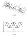
- Figure 1 shows an optoelectronic measuring device with an embodiment of the reference unit of the invention.
- Said device comprises a readhead 1 and a scale 2 that is fixed to a bedplate 4.
- the readhead 1 moves relative to the scale 2 in a direction X, generating counting signals A and B.
- Said readhead 1 comprises a plurality of photodetectors (not shown in the figures), and said scale 2 comprises a plurality of marks 2' distributed along the direction X.
- Said photodetectors detect the marks 2', and in accordance with said detection, said readhead 1 generates the counting signals A and B.
- the marks 2' are detected by reflection.
- the readhead 1 emits a beam of light that is reflected on the scale 2, with said reflected light reaching the photodetectors, and said photodetectors detecting the marks 2' by means of said reflected light.
- the reference unit 5 of the invention comprises a reference support 3 that is fixed to the bedplate 4, being disposed parallel to the scale 2, and an optical reference mark 30, usually known as I0, disposed on said reference support 3.
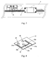
- the readhead 1 generates a reference signal R when detecting said reference mark 30 during its movement relative to the scale 2.
- the photodetectors detect the reference mark 30, with said readhead 1 generating the reference signal R in accordance with said detection.
- the beam of light emitted by said readhead 1 falls on said reference support 3 and is reflected on said reference mark 30, with the reflected light reaching said photodetectors, and said photodetectors detecting the reference mark 30 in accordance with said reflected light.
- Both the counting signals A and B and the reference signal R reach control means (not shown in the figures), and are used to determine the position of said readhead 1 in relation to the scale 2. Said counting signals A and B determine the incremental position of said readhead 1 in relation to said scale 2, taking the reference signal R as a reference point.
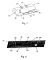
- the reference support 3 comprises adjusting means to move the reference mark 30 longitudinally, with the reference unit 5 remaining fixed to the bedplate 4. In this way, once said reference unit 5 is fixed to said bedplate 4, said reference mark 30 can be moved to synchronise the reference signal R with one of the counting signals A and B, as shown in figure 2 . To synchronise said reference signal R with one of said counting signals A and B, said reference mark 30 is aligned with one of the marks 2', as shown in figure 3 .
- the reference support 3 comprises a support plate 31 with a first area 31a joined to the bedplate 4, and a second area 31b that comprises the reference mark 30, as shown in figure 4 .
- the support plate 31 comprises a separation channel 32 between said first area 31a and said second area 31b.
- the separation channel 32 is U-shaped and comprises two transverse sections 32a and a longitudinal section 32b. Said separation channel 32 delimits the second area 31b.
- the adjusting means comprise an adjusting screw (not shown in the figures), with the second area 31b of the support plate 31 being pushed by said adjusting screw, moving said second area 31b longitudinally.
- the adjusting means also comprise a tab 33, with the adjusting screw pushing said tab 33, and said tab 33 pushing said second area 31b.
- the reference support 3 comprises a body 34, with the support plate 31 being housed in said body 34.
- the adjusting screw is housed in a housing 35 disposed in said body 34.
- said body 34 is fixed to the bedplate 4 by means of two fixing screws 37 and 37', although it can also be glued.
- the support plate 31 comprises two holes 38 and 38' in the first area 31a to allow said fixing screws 37 and 37' to pass through, so that said first area 31a is joined to said bedplate 4.
- the tab 33 is comprised in said body 34.
- the separation channel 32 of the support plate 31 delimits the first area 31a, and the tab 33 is disposed in the second area 31b of the support plate 31.
- the adjusting screw pushes said tab 33, with said tab 33 pushing said second area 31b, moving the reference mark 30 longitudinally.
- the reference support 3 comprises a magnet 36
- the readhead 1 comprises at least one Hall-effect sensor (not shown in the figures), with said Hall sensor detecting the magnet 36 when said readhead 1 passes over said magnet 36. If, in the presence of said magnet 36, the photodetectors detect a mark, said mark is determined to be corresponding with the reference mark 30, generating the reference signal R.
Landscapes
- Physics & Mathematics (AREA)
- General Physics & Mathematics (AREA)
- Optical Transform (AREA)
- Length Measuring Devices By Optical Means (AREA)
Claims (9)
- Unité de référence pour dispositif de mesure optoélectronique, ledit dispositif comprenant une tête de lecture (1) et une échelle (2) fixée sur une plaque de base (4), la tète de lecture (1) se déplaçant par rapport à l'échelle (2) ce qui génère des signaux de comptage (A, B), et l'unité de référence (5) comprenant un support de référence (3) qui est fixé sur la plaque de base (4) qui est parallèle à ladite échelle (2) et au moins une marque de référence (30) disposé sur ledit support de référence (3), la tête de lecture (1) étant adaptée pour générer un signal de référence (R) lors de la détection de ladite marque de référence (30), la position de la tête de lecture (1) par rapport à ladite échelle (2) étant déterminée en fonction desdits signaux de comptage (A, B) en prenant ledit signal de référence (R) comme référence, caractérisé en ce que le support de référence (3) comprend des moyens d'ajustement pour déplacer la marque de référence (30) de manière longitudinale ledit support de référence (3) restant fixé sur la plaque de base (4) et une plaque support (31) dont une première zone (31 a) est connectée à la plaque de base (4) et dont une seconde zone (31b) comprend la marque de référence (30), ladite plaque support (31) comprenant un canal de séparation (32) placé entre ladite première zone (31 a) et ladite seconde zone (31 b) et ladite seconde zone (31b) étant déplaçable de manière longitudinale par rapport à ladite première zone (31 a) au moyen de moyens d'ajustement de manière à ce que le signal de référence (R) soit synchronisé avec les signaux de comptage (A, B).
- Unité de référence selon la revendication précédente où le canal de séparation (32) est en forme de U.
- Unité de référence selon la revendication précédente où le canal de séparation (32) comprend deux sections transversales (32a) et une section longitudinale (32b).
- Unité de référence selon la revendication précédente où le canal de séparation (32) délimite la seconde zone (31 b) de la plaque support (31).
- Unité de référence selon la revendication 3 où le canal de séparation (32) délimite la première zone (31 a) de la plaque support (31).
- Unité de référence selon l'une quelconque des revendications précédentes où les moyens d'ajustement comprennent une vis de réglage, la seconde zone (31 b) de la plaque support (31) étant poussée au moyen de ladite vis de réglage, ce qui déplace la seconde zone (31 b) de manière longitudinale par rapport à la première zone (31 a).
- Unité de référence selon la revendication précédente où les moyens d'ajustement comprennent un onglet (33) qui est poussé par la vis de réglage et ledit onglet (33) exerce à son tour une pression sur la seconde zone (31 b) de la plaque support (31).
- Unité de référence selon l'une quelconque des revendications précédentes où le support de référence (3) comprend un corps (34), la plaque support (31) étant logée dans ledit corps (34) et ce corps (34) étant fixé sur la plaque de base (4).
- Unité de référence selon l'une quelconque des revendications précédentes où le support de référence (3) comprend un aimant (36) et la tête de lecture (1) génère un signal de référence (R) lors de la détection de la marque de référence et dudit aimant (36).
Priority Applications (3)
| Application Number | Priority Date | Filing Date | Title |
|---|---|---|---|
| EP20050380224 EP1775558B1 (fr) | 2005-10-13 | 2005-10-13 | Unité de reférence pour un dispositif de mesure optoélectronique. |
| DE200560027465 DE602005027465D1 (de) | 2005-10-13 | 2005-10-13 | Referenzeinheit für ein optoelektronisches Messgerät. |
| ES05380224T ES2360226T3 (es) | 2005-10-13 | 2005-10-13 | Unidad de referencia para un dispositivo optoelectrónico de medida. |
Applications Claiming Priority (1)
| Application Number | Priority Date | Filing Date | Title |
|---|---|---|---|
| EP20050380224 EP1775558B1 (fr) | 2005-10-13 | 2005-10-13 | Unité de reférence pour un dispositif de mesure optoélectronique. |
Publications (2)
| Publication Number | Publication Date |
|---|---|
| EP1775558A1 EP1775558A1 (fr) | 2007-04-18 |
| EP1775558B1 true EP1775558B1 (fr) | 2011-04-13 |
Family
ID=36016180
Family Applications (1)
| Application Number | Title | Priority Date | Filing Date |
|---|---|---|---|
| EP20050380224 Expired - Lifetime EP1775558B1 (fr) | 2005-10-13 | 2005-10-13 | Unité de reférence pour un dispositif de mesure optoélectronique. |
Country Status (3)
| Country | Link |
|---|---|
| EP (1) | EP1775558B1 (fr) |
| DE (1) | DE602005027465D1 (fr) |
| ES (1) | ES2360226T3 (fr) |
Families Citing this family (2)
| Publication number | Priority date | Publication date | Assignee | Title |
|---|---|---|---|---|
| DE602009000745D1 (de) * | 2009-03-02 | 2011-03-31 | Fagor S Coop | Lesekopf für ein optisches Positionsmessgerät |
| EP3015828B1 (fr) | 2014-10-30 | 2016-09-28 | Fagor, S. Coop. | Dispositif optoélectronique et procédé associé |
Family Cites Families (1)
| Publication number | Priority date | Publication date | Assignee | Title |
|---|---|---|---|---|
| GB9605278D0 (en) * | 1996-03-13 | 1996-05-15 | Renishaw Plc | Opto-electronic scale reading apparatus |
-
2005
- 2005-10-13 DE DE200560027465 patent/DE602005027465D1/de not_active Expired - Lifetime
- 2005-10-13 ES ES05380224T patent/ES2360226T3/es not_active Expired - Lifetime
- 2005-10-13 EP EP20050380224 patent/EP1775558B1/fr not_active Expired - Lifetime
Also Published As
| Publication number | Publication date |
|---|---|
| EP1775558A1 (fr) | 2007-04-18 |
| ES2360226T3 (es) | 2011-06-02 |
| DE602005027465D1 (de) | 2011-05-26 |
Similar Documents
| Publication | Publication Date | Title |
|---|---|---|
| EP1980824B1 (fr) | Codeur de type mesure de la longueur absolue de la position | |
| EP2212651B1 (fr) | Codeur magnétique et applicateur de marque de référence | |
| WO2002061366A3 (fr) | Systeme de magnetisation pour produire un changement lineaire dans un angle de champ | |
| WO2007006555A3 (fr) | Dispositif capteur d'angle | |
| AU2003208299A1 (en) | Optical displacement sensor | |
| US7326919B2 (en) | Optical encoder | |
| KR102353097B1 (ko) | 위치 측정 장치 | |
| DE50015209D1 (de) | Optische Positionsmesseinrichtung | |
| US20070206174A1 (en) | Hand-Held Device For Measuring Distances | |
| US20080204006A1 (en) | Linear position sensor | |
| WO2002004895A3 (fr) | Capteur de position optique et procede de determination de position | |
| JP2005337843A (ja) | 光学式エンコーダ | |
| EP1775558B1 (fr) | Unité de reférence pour un dispositif de mesure optoélectronique. | |
| JP2945883B2 (ja) | 移動する機械部品の位置検知方法および装置 | |
| US7421800B2 (en) | Scale reading apparatus | |
| US7599070B2 (en) | Optical axis polarization type laser interferometer | |
| EP1502858A3 (fr) | Machine automatique pour traiter des objets avec un dispositif pour détecter une position à capteurs à effet Halle | |
| JP2004233346A (ja) | 互いに対して動きうる二個の機械部品の相対的な動きを検出するための装置及び方法 | |
| JP2004361411A (ja) | 受光装置 | |
| WO2021058086A1 (fr) | Agencement de mesure de déplacement doté d'un capteur à effet hall et d'un aimant | |
| US8400643B2 (en) | Displacement sensor using multiple position sensitive photodetectors | |
| JP2017227456A (ja) | 作動機構の原点位置検出方法並びに原点位置検出装置 | |
| JP2009516187A (ja) | スケールおよび読み取りヘッド装置および方法 | |
| US20030178557A1 (en) | Position encoder | |
| US11085796B2 (en) | Sensor device |
Legal Events
| Date | Code | Title | Description |
|---|---|---|---|
| PUAI | Public reference made under article 153(3) epc to a published international application that has entered the european phase |
Free format text: ORIGINAL CODE: 0009012 |
|
| 17P | Request for examination filed |
Effective date: 20060608 |
|
| AK | Designated contracting states |
Kind code of ref document: A1 Designated state(s): AT BE BG CH CY CZ DE DK EE ES FI FR GB GR HU IE IS IT LI LT LU LV MC NL PL PT RO SE SI SK TR |
|
| AX | Request for extension of the european patent |
Extension state: AL BA HR MK YU |
|
| AKX | Designation fees paid |
Designated state(s): DE ES IT |
|
| GRAP | Despatch of communication of intention to grant a patent |
Free format text: ORIGINAL CODE: EPIDOSNIGR1 |
|
| GRAC | Information related to communication of intention to grant a patent modified |
Free format text: ORIGINAL CODE: EPIDOSCIGR1 |
|
| GRAS | Grant fee paid |
Free format text: ORIGINAL CODE: EPIDOSNIGR3 |
|
| GRAA | (expected) grant |
Free format text: ORIGINAL CODE: 0009210 |
|
| AK | Designated contracting states |
Kind code of ref document: B1 Designated state(s): DE ES IT |
|
| REF | Corresponds to: |
Ref document number: 602005027465 Country of ref document: DE Date of ref document: 20110526 Kind code of ref document: P |
|
| REG | Reference to a national code |
Ref country code: DE Ref legal event code: R096 Ref document number: 602005027465 Country of ref document: DE Effective date: 20110526 |
|
| REG | Reference to a national code |
Ref country code: ES Ref legal event code: FG2A Ref document number: 2360226 Country of ref document: ES Kind code of ref document: T3 Effective date: 20110602 |
|
| PLBE | No opposition filed within time limit |
Free format text: ORIGINAL CODE: 0009261 |
|
| STAA | Information on the status of an ep patent application or granted ep patent |
Free format text: STATUS: NO OPPOSITION FILED WITHIN TIME LIMIT |
|
| 26N | No opposition filed |
Effective date: 20120116 |
|
| REG | Reference to a national code |
Ref country code: DE Ref legal event code: R097 Ref document number: 602005027465 Country of ref document: DE Effective date: 20120116 |
|
| PG25 | Lapsed in a contracting state [announced via postgrant information from national office to epo] |
Ref country code: IT Free format text: LAPSE BECAUSE OF FAILURE TO SUBMIT A TRANSLATION OF THE DESCRIPTION OR TO PAY THE FEE WITHIN THE PRESCRIBED TIME-LIMIT Effective date: 20110413 |
|
| PGFP | Annual fee paid to national office [announced via postgrant information from national office to epo] |
Ref country code: ES Payment date: 20121022 Year of fee payment: 8 |
|
| PGFP | Annual fee paid to national office [announced via postgrant information from national office to epo] |
Ref country code: DE Payment date: 20131021 Year of fee payment: 9 |
|
| REG | Reference to a national code |
Ref country code: ES Ref legal event code: FD2A Effective date: 20141107 |
|
| PG25 | Lapsed in a contracting state [announced via postgrant information from national office to epo] |
Ref country code: ES Free format text: LAPSE BECAUSE OF NON-PAYMENT OF DUE FEES Effective date: 20131014 |
|
| REG | Reference to a national code |
Ref country code: DE Ref legal event code: R119 Ref document number: 602005027465 Country of ref document: DE |
|
| PG25 | Lapsed in a contracting state [announced via postgrant information from national office to epo] |
Ref country code: DE Free format text: LAPSE BECAUSE OF NON-PAYMENT OF DUE FEES Effective date: 20150501 |