EP1775572A2 - Messung von Flüssigteilchen in Gasströmen - Google Patents
Messung von Flüssigteilchen in Gasströmen Download PDFInfo
- Publication number
- EP1775572A2 EP1775572A2 EP06020950A EP06020950A EP1775572A2 EP 1775572 A2 EP1775572 A2 EP 1775572A2 EP 06020950 A EP06020950 A EP 06020950A EP 06020950 A EP06020950 A EP 06020950A EP 1775572 A2 EP1775572 A2 EP 1775572A2
- Authority
- EP
- European Patent Office
- Prior art keywords
- gas
- pressure
- monitor
- particles
- approximately
- Prior art date
- Legal status (The legal status is an assumption and is not a legal conclusion. Google has not performed a legal analysis and makes no representation as to the accuracy of the status listed.)
- Withdrawn
Links
- 239000002245 particle Substances 0.000 title claims abstract description 83
- 239000007788 liquid Substances 0.000 title claims abstract description 72
- 238000005259 measurement Methods 0.000 title description 6
- 239000007789 gas Substances 0.000 claims abstract description 184
- 238000001514 detection method Methods 0.000 claims abstract description 51
- 230000004044 response Effects 0.000 claims abstract description 13
- 238000000034 method Methods 0.000 claims description 22
- 238000000149 argon plasma sintering Methods 0.000 claims description 8
- 238000004891 communication Methods 0.000 claims description 8
- 150000002430 hydrocarbons Chemical class 0.000 claims description 7
- 239000010419 fine particle Substances 0.000 claims description 6
- 239000004215 Carbon black (E152) Substances 0.000 claims description 4
- 230000008859 change Effects 0.000 claims description 4
- 239000002826 coolant Substances 0.000 claims description 4
- 229930195733 hydrocarbon Natural products 0.000 claims description 4
- 239000000314 lubricant Substances 0.000 claims description 4
- 239000000203 mixture Substances 0.000 claims description 4
- NBVXSUQYWXRMNV-UHFFFAOYSA-N fluoromethane Chemical class FC NBVXSUQYWXRMNV-UHFFFAOYSA-N 0.000 claims description 3
- 150000005826 halohydrocarbons Chemical class 0.000 claims description 3
- 239000000463 material Substances 0.000 claims description 3
- 229920001296 polysiloxane Polymers 0.000 claims description 3
- 230000008878 coupling Effects 0.000 claims description 2
- 238000010168 coupling process Methods 0.000 claims description 2
- 238000005859 coupling reaction Methods 0.000 claims description 2
- -1 e.g. Substances 0.000 abstract description 10
- 239000001257 hydrogen Substances 0.000 abstract description 7
- 229910052739 hydrogen Inorganic materials 0.000 abstract description 7
- 230000035945 sensitivity Effects 0.000 abstract description 4
- 125000004435 hydrogen atom Chemical class [H]* 0.000 abstract 1
- 239000003921 oil Substances 0.000 description 36
- 238000010926 purge Methods 0.000 description 26
- VNWKTOKETHGBQD-UHFFFAOYSA-N methane Chemical compound C VNWKTOKETHGBQD-UHFFFAOYSA-N 0.000 description 18
- IJGRMHOSHXDMSA-UHFFFAOYSA-N Atomic nitrogen Chemical compound N#N IJGRMHOSHXDMSA-UHFFFAOYSA-N 0.000 description 10
- 239000003345 natural gas Substances 0.000 description 7
- 239000000356 contaminant Substances 0.000 description 6
- 239000003595 mist Substances 0.000 description 6
- UFHFLCQGNIYNRP-UHFFFAOYSA-N Hydrogen Chemical compound [H][H] UFHFLCQGNIYNRP-UHFFFAOYSA-N 0.000 description 5
- 239000012530 fluid Substances 0.000 description 5
- 229910052757 nitrogen Inorganic materials 0.000 description 5
- 238000009423 ventilation Methods 0.000 description 5
- 238000011109 contamination Methods 0.000 description 4
- 238000004519 manufacturing process Methods 0.000 description 4
- 230000009471 action Effects 0.000 description 3
- 238000010276 construction Methods 0.000 description 3
- 230000000694 effects Effects 0.000 description 3
- 238000012544 monitoring process Methods 0.000 description 3
- 239000000047 product Substances 0.000 description 3
- ATUOYWHBWRKTHZ-UHFFFAOYSA-N Propane Chemical compound CCC ATUOYWHBWRKTHZ-UHFFFAOYSA-N 0.000 description 2
- BLRPTPMANUNPDV-UHFFFAOYSA-N Silane Chemical compound [SiH4] BLRPTPMANUNPDV-UHFFFAOYSA-N 0.000 description 2
- 238000009833 condensation Methods 0.000 description 2
- 230000005494 condensation Effects 0.000 description 2
- 239000002360 explosive Substances 0.000 description 2
- 150000008282 halocarbons Chemical class 0.000 description 2
- 238000011144 upstream manufacturing Methods 0.000 description 2
- UGFAIRIUMAVXCW-UHFFFAOYSA-N Carbon monoxide Chemical compound [O+]#[C-] UGFAIRIUMAVXCW-UHFFFAOYSA-N 0.000 description 1
- ZAMOUSCENKQFHK-UHFFFAOYSA-N Chlorine atom Chemical compound [Cl] ZAMOUSCENKQFHK-UHFFFAOYSA-N 0.000 description 1
- PXGOKWXKJXAPGV-UHFFFAOYSA-N Fluorine Chemical compound FF PXGOKWXKJXAPGV-UHFFFAOYSA-N 0.000 description 1
- 239000003463 adsorbent Substances 0.000 description 1
- 239000000443 aerosol Substances 0.000 description 1
- QVGXLLKOCUKJST-UHFFFAOYSA-N atomic oxygen Chemical compound [O] QVGXLLKOCUKJST-UHFFFAOYSA-N 0.000 description 1
- 239000001273 butane Substances 0.000 description 1
- 229910002091 carbon monoxide Inorganic materials 0.000 description 1
- 230000015556 catabolic process Effects 0.000 description 1
- 239000003054 catalyst Substances 0.000 description 1
- 239000000460 chlorine Substances 0.000 description 1
- 229910052801 chlorine Inorganic materials 0.000 description 1
- 230000001427 coherent effect Effects 0.000 description 1
- 230000001419 dependent effect Effects 0.000 description 1
- 238000010586 diagram Methods 0.000 description 1
- 229920001971 elastomer Polymers 0.000 description 1
- 239000000806 elastomer Substances 0.000 description 1
- 238000004880 explosion Methods 0.000 description 1
- 239000012467 final product Substances 0.000 description 1
- 239000011737 fluorine Substances 0.000 description 1
- 229910052731 fluorine Inorganic materials 0.000 description 1
- 238000011010 flushing procedure Methods 0.000 description 1
- 239000004519 grease Substances 0.000 description 1
- 238000010438 heat treatment Methods 0.000 description 1
- 150000002431 hydrogen Chemical class 0.000 description 1
- 238000005984 hydrogenation reaction Methods 0.000 description 1
- 238000002955 isolation Methods 0.000 description 1
- 229940075473 medical gases Drugs 0.000 description 1
- 229910052751 metal Inorganic materials 0.000 description 1
- 239000002184 metal Substances 0.000 description 1
- 150000002739 metals Chemical class 0.000 description 1
- 238000012986 modification Methods 0.000 description 1
- 230000004048 modification Effects 0.000 description 1
- IJDNQMDRQITEOD-UHFFFAOYSA-N n-butane Chemical compound CCCC IJDNQMDRQITEOD-UHFFFAOYSA-N 0.000 description 1
- OFBQJSOFQDEBGM-UHFFFAOYSA-N n-pentane Natural products CCCCC OFBQJSOFQDEBGM-UHFFFAOYSA-N 0.000 description 1
- 230000000474 nursing effect Effects 0.000 description 1
- 239000001301 oxygen Substances 0.000 description 1
- 229910052760 oxygen Inorganic materials 0.000 description 1
- 239000013618 particulate matter Substances 0.000 description 1
- 238000012545 processing Methods 0.000 description 1
- 239000001294 propane Substances 0.000 description 1
- 238000002407 reforming Methods 0.000 description 1
- 230000000246 remedial effect Effects 0.000 description 1
- 230000008439 repair process Effects 0.000 description 1
- 230000029058 respiratory gaseous exchange Effects 0.000 description 1
- 229910000077 silane Inorganic materials 0.000 description 1
- 239000007787 solid Substances 0.000 description 1
- 229910001220 stainless steel Inorganic materials 0.000 description 1
- 239000010935 stainless steel Substances 0.000 description 1
- 238000003860 storage Methods 0.000 description 1
- XLYOFNOQVPJJNP-UHFFFAOYSA-N water Substances O XLYOFNOQVPJJNP-UHFFFAOYSA-N 0.000 description 1
Images

Classifications
-
- G—PHYSICS
- G01—MEASURING; TESTING
- G01N—INVESTIGATING OR ANALYSING MATERIALS BY DETERMINING THEIR CHEMICAL OR PHYSICAL PROPERTIES
- G01N15/00—Investigating characteristics of particles; Investigating permeability, pore-volume or surface-area of porous materials
- G01N15/06—Investigating concentration of particle suspensions
-
- G—PHYSICS
- G01—MEASURING; TESTING
- G01N—INVESTIGATING OR ANALYSING MATERIALS BY DETERMINING THEIR CHEMICAL OR PHYSICAL PROPERTIES
- G01N15/00—Investigating characteristics of particles; Investigating permeability, pore-volume or surface-area of porous materials
- G01N15/06—Investigating concentration of particle suspensions
- G01N15/075—Investigating concentration of particle suspensions by optical means
Definitions
- This invention relates generally to liquid particle/droplet detecting systems, and more particularly to systems for detecting particles or droplets of liquids, e.g., oils, in gas systems making use of at least one gas compressor or other device which may introduce fine particles of such liquid(s) into gas in the system.
- liquids e.g., oils
- oil mist may enter into the conduit carrying the natural gas as a result of leakage of oil from seals of compressors.
- the presence of such minute particles or droplets of oil (sometimes referred to as "oil droplet breakthrough") can contaminate the natural gas.
- oil mist in natural gas feed stock may reduce the efficiency of the hydrogenation catalyst by deactivating it and also causing it to "cake", thereby creating a pressure drop across a hydrogenator/desulfurizer.
- the patented prior art includes various particle detecting devices that make use of light scattering techniques to detect the presence of particles in fluid streams.
- particle detectors each of which employs a laser disposed in a resonant cavity and an intra-cavity view volume.
- the resonant cavity is defined by two spaced apart mirrors, with the laser medium positioned between them, defining a light path.
- a pump source is optically coupled to drive the laser medium to produce coherent light having a first wavelength.
- the view volume is positioned in the light path, between the first mirror and the laser medium, to introduce particles into the resonant cavity so that light impinging there-upon produces scattered light.
- a detector is disposed to sense light scattered from the view volume and produces signals proportional to the light sensed.
- a displaying device such as a pulse height analyzer, is in electrical communication to receive the signals produced by the detector to quantitatively display the intensity of the light sensed.
- DE 10162278 discloses a system of detecting the presence of air compressor produced oil droplets in compressed gas stream by heating and expanding a partial aerosol stream, to thereby transform the droplets into a gas which is subsequently analyzed by a gas sensor.
- Thermo Andersen, Inc. of Franklin, MA sells a HPM-1000 particulate monitor that is designed to be installed directly in line with compressed air/gas streams to provide continuous measurement of oil mist carryover, entrained water mist, and particulate contamination at pressures up to 350 psig.
- the HPM-1000 monitor uses a high sensitivity nephalometric (photometric) sensor, whose light scattering detection configuration has been optimized for the measurement of fine particle contamination in compressed air and gas streams.
- our co-pending application discloses a system for detecting fine liquid, e.g., oil, particles in a gas system having a high pressure compressor and at least two gas handling devices, e.g., a coalescer and at least one adsorber.
- the detection system uses plural sensors and a monitor unit. Each of the monitors is arranged for detecting the presence of fine liquid particles in the gas by means of light scattering and for providing an output signal to a data acquisition unit.
- the data acquisition unit operates in response to the detection of the fine liquid particles in various portions of the gas system and to provide alert signals in response thereto.
- the alert signals can be used to control associated valves in the gas system to bring about a desired result.
- the prior art systems as disclosed above may not be suitable, e.g., they may be too complex or expensive.
- automated control may not be necessary.
- the systems and methods of the invention of our co-pending application, absent its feed-back or automated control aspects, can be used for such simplified (e.g., non-automatic control) applications.
- the subject invention is directed to providing systems and methods to aid in identification of fine oil (or other liquid) particles into a downstream gas supply by monitoring the gas at one point and reacting to any appreciable increase in oil levels to provide a signal indicative of the absolute value of the liquid detected.
- the systems and methods of the subject invention are capable of detecting extremely low levels of liquid particles.
- the usage of the systems and methods of this invention enables an early warning of oil/liquid droplet presence that may be an unsafe or unhealthy environment, or indicative of a pump/compressor/fan failure.
- a detection system for detecting the presence of fine liquid particles in a gas system including a compressor or other device which may introduce fine liquid particles into a gas -carrying conduit.
- the detection system comprises a first monitor, a data acquisition unit and pressure and flow control means.
- the first monitor is arranged for detecting the presence of fine liquid, e.g., oil, particles in the gas by means of light scattering and for providing an output signal to the data acquisition unit in response to the detection of such fine liquid particles.
- the first monitor is in communication with the interior of the first gas-carrying conduit.
- the pressure and flow control means is arranged to control the pressure and flow rate of the gas in the gas-carrying conduit at the first monitor so that it is within a predetermined range, whereupon the data acquisition unit provides at least one output signal indicative of an absolute value change in the mass count of any fine liquid particles in the gas carrying conduit.
- a method for detecting the presence of fine liquid particles in a gas system e.g., a natural gas system or an aircraft ventilation system
- the gas system comprising a compressor or other device which may introduce fine liquid particles into a gas -carrying conduit.
- the detection system comprises a first monitor, a data acquisition unit and pressure and flow control means.
- the first monitor is arranged for detecting the presence of fine liquid particles in the gas by means of light scattering and for providing an output signal to the data acquisition unit in response to the detection of such fine liquid particles.
- the method comprises coupling the first monitor in communication with the interior of the first gas-carrying conduit, operating the pressure and flow control means to control the pressure and flow rate of the gas in the gas-carrying conduit at the first monitor, whereupon the pressure and flow rate of the gas in the gas-carrying conduit is within a predetermined range, and operating said data acquisition unit to provide at least one output signal indicative of an absolute value change in the mass count of any fine liquid particles in the gas carrying conduit.
- the pressure and flow control means is adjustable in automatic response to a signal from the data acquisition unit, e.g., the pressure and flow control means is arranged to control the flow within a range of approximately +/- 2% for rates in the range of approximately 1 to 30 liters per minute, and to control the pressure within a range of +/- 10 PSIG for pressures in the range of approximately 100 to 350 PSIG and approximately +/- 5% of the value in the range 1 to 100 PSIG.
- Fig. 1 is a schematic view of one exemplary embodiment of the detection system of the subject invention shown in an exemplary embodiment of a conventional gas system, e.g., a non-flammable gas system;
- a conventional gas system e.g., a non-flammable gas system
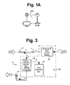
- Fig. 1A is a schematic diagram of one exemplary portion of the exemplary flow and pressure control means used in the system of Fig. 1;
- Fig. 2 is a schematic view of the embodiment of the detection system shown in Fig. 1 configured for use in another exemplary embodiment of a conventional gas system, e.g., a flammable gas system; and
- Fig. 3 is a schematic view of the embodiment of the detection system shown in Fig. 1 configured for use in another exemplary embodiment of a gas system, in this case a HVAC or other ventilation system, such as may be found in an aircraft, in an enclosed environment manufacturing facility, etc.
- a gas system in this case a HVAC or other ventilation system, such as may be found in an aircraft, in an enclosed environment manufacturing facility, etc.
- each of the systems 20A, 20B and 20C comprises a single particulate detection monitor 22, an associated data acquisition unit 24 and pressure and flow control means 26. The details and operation of those components will be described later and are consistent with that described in our aforementioned co-pending patent application.
- this invention can be used in any systems including components, e.g., lubricated valves, fittings, etc., including a grease, oil, other lubricants, coolants, etc. which may be enable any type of liquid to be drawn into (or otherwise introduced) a gas stream.
- the gas stream may be an elemental gas (such as hydrogen, etc.), combined elemental gases (such as Silane (SiH 4 ), CO 2 , etc.), a hydrocarbon gas (such as methane, propane, butane, etc.), a halohydrocarbon gas (such as Suva® gases containing either fluorine or chlorine, etc.) or mixtures of gases (such as air).
- an elemental gas such as hydrogen, etc.
- combined elemental gases such as Silane (SiH 4 ), CO 2 , etc.
- a hydrocarbon gas such as methane, propane, butane, etc.
- a halohydrocarbon gas such as Suva® gases containing either fluorine or chlorine, etc
- ultra-pure hydrogen is required.
- the presence of even minute amounts of oil or other liquid particles in the hydrogen may result in an inferior product.
- industries frequently demand that the hydrogen have as low a hydrocarbon content as possible.
- the subject invention can be used to achieve that end.
- the gas system 1A (Fig. 1) in which the detection system 20A is used comprises a gas supply system carrying a non-flammable gas.
- the gas supply system 2B in which the detection system 20B is used comprises a gas supply system making use of a flammable gas.
- the system 1C in which the detection system 20C is used comprises an HVAC system or any other system carrying air, e.g., a ventilation system to the interior of an aircraft, a clean room or other controlled environment. It must be pointed out at this juncture that the systems 1A, 1B and 1C are merely exemplary of many types of gas systems making use of at least one high pressure gas compressor or other device which may introduce fine oil particles into a gas stream.
- the gas system 1A receives the gas to be monitored (the gas is identified by the legend "Sample” within the arrow shown in Fig. 1) from a conduit 2 carrying that gas. Located upstream of the conduit is any device or component (not shown) that may introduce fine liquid particles or droplets as a mist into the gas stream.
- the pressure and flow control means 26 is connected in the conduit 2 and its output is provided via a conduit 3. Downstream of the pressure and flow control means 26 is a manual shut-off (on/off) valve 4 in the conduit 3.
- a safety pressure relief valve 5 is located in the conduit 3 downstream of the valve 4.
- An optional isolation valve 6 is located in the conduit 4 downstream of the relief valve 5.
- the output of the valve 6 is provided via a conduit 7.
- a restrictor, e.g., needle valve, 8 is located in the conduit 7.
- the conduit 7 is connected to a conduit 9 which serves as the input to the particulate detection monitor 22 of the fine liquid particle/droplet detection system 20A.
- the conduit 9 serves to carry the gas to be sampled for liquid particulates (i.e., the "Sample” gas) to the monitor 22.
- the monitor 22 is arranged to provide electrical output signals indicative of the level of oil or other liquid particles in the gas in the conduit 9 to the data acquisition unit 24 via an electrical line 10.
- the system 1A includes another input to the monitor. That input is provided via a conduit 11 and serves to carry a purge gas, e.g., nitrogen (designated by the legend "Zero N 2 " within the arrow shown in Fig. 1) from a gas source (not shown).
- a purge gas e.g., nitrogen (designated by the legend "Zero N 2 " within the arrow shown in Fig. 1) from a gas source (not shown).
- the purge gas input conduit 11 merges with the sample gas conduit 7 as a joint input into the conduit 9 leading to the monitor 22.
- a manual shut off valve 12 is connected in the purge gas input line 11 between the source of the purge gas and conduit 9.
- the gas output of the monitor 22 is provided by a conduit 13 to vent the gas to some means (not shown and designated by the legend "Vent" within the arrow shown in Fig. 1).
- a flow meter 14 (whose function and operation will be described later) is located in the conduit 13 between the monitor and the vent.
- the gases may be compressed using halocarbon oil lubed equipment.
- oil-less compressors/pumps are used.
- the subject invention has application for use in medical gas monitoring systems, e.g. in-home care, hospitals, nursing homes and clinics.
- the purging of the monitor 22 of any residual contaminants is accomplished by closing the manual shut off valve 4, thereby preventing any of the Sample gas from gaining access to the monitor via conduit 8.
- the manual shut off valve 11 can then be opened to introduce a purge gas, e.g., nitrogen, via communicating conduits 11 and 9 into the monitor 22.
- a purge gas e.g., nitrogen
- the optional valve 6 may be closed, to thereby prevent the purge gas from flowing upstream, in case the valve 4 was not shut.
- the introduction of the purge gas into the system so that it flows through the monitor 22 has the effect of flushing any contaminants out of the monitor via output conduit 13 and flow valve 14 to the vent.
- the valve 12 is arranged to be adjusted so that the rate of flow of the purge gas through the monitor can be made consistent with the rate of flow of the Sample gas through the monitor 22, e.g., 25 liters/minute, thereby ensuring accurate calibration of the monitor.
- the presence of the flow meter 14 in the output conduit 13 enables one to readily adjust the flow rate of the purge gas to the desired level.
- the system 20A After the system 20A has been purged, it can be calibrated to a zero level. Once this has been accomplished the detection system 20A is ready for use with the Sample gas to detect the presence and absolute value of any liquid particles therein.
- the detection system 20A comprises a single particulate detection monitor 22, the data acquisition unit 22 and the pressure and flow control means 26.
- the monitor 22 makes use of a high sensitivity nephalometric (photometric) sensor and is connected to the data acquisition unit via line 10.
- the data acquisition unit may be any conventional device, such as data logger, a computer or a portion of a distributed control system (DCS) of the facility operating the system 1A.
- One particularly suitable particle commercially available monitor unit 22 is the above mentioned HPM-1000 particulate monitor of Thermo Andersen, Inc. As mentioned above, this monitor and its associated sensor is designed to measure the concentration of gas borne particulate matter (liquid or solid), at pressures up to 350 psig.
- the high sensitivity nephalometric (photometric) sensors' light scattering detection configuration of this invention is optimized for the measurement of fine particle contamination in compressed air and gas streams.
- the system 20A is designed to work within the following parameters: Sample Pressures: 0 psig - 350 psig. Sample Flow Rates: 1 L/min - 30 Umin. Sensor Electrical Requirements: 90 - 265 VAC, 50 - 60 Hz. Measurement Range: 0.01 mg/m3 to 400 mg/m3 or 0.03 ug/ft3 to 11,330 ug/ft3. It should be pointed out at this juncture that other oil or other liquid particle monitors can be used in lieu of the HPM-1000 monitor.
- the HPM-1000 high pressure particulate monitor is specified by its manufacturer as being capable of measurement and calibration independent of flow rate. However, it has been discovered that enhanced effective and accurate usage, the flow rate and pressure be controlled.
- the input to the HPM1-1000 the monitor 22 is via the pressure and flow control means 26. That means comprises any commercially available devices, such as a pressure control valve 26A and a flow control valve and associated components collectively designated by the reference number 26B and shown in more detail in Fig. 1A. Such devices are available from Swagelock Company of Solon, OH, Parker Hannifin Corporation of Cleveland, OH and others.
- the valves 26A and 26B are connected in series between the monitor 22 and the line, conduit or device carrying the sample gas.
- the valves may be adjusted manually or under automated control from a data logger (not shown) or any other associated equipment.
- Each of the pressure and flow control means is arranged to control the flow within a range of approximately +/- 2% for rates in the range of approximately 1 to 30 liters per minute, and to control the pressure within a range of +/- 10 psig for pressures in the range of approximately 100 to 350 psig and approximately +/- 5% of the value in the range of approximately 1 to 100 psig.
- the settings for the pressure and flow are dependent upon the conditions of the system 1 in which the subject invention is to be used.
- the pressure and flow rate of the system 1A at the location where the monitor 22 is to be located should be determined and the appropriate setting of pressure and flow made consistent therewith. Also, it is desirable to set the pressure as low as possible and consistent with the make-up of the system 1A to prevent the liquid particles/droplets from condensing out of the gas and onto the conduit, tubing or device(s) in which the gas passes.
- One exemplary setting for the pressure and flow could be a pressure of approximately 15 psi at a flow rate of approximately 25 liters/minute. It has been determined that particle size for detection by the specific embodiment of the monitor 22 disclosed above can be in the range of 0.1 to 10 microns (e.g., or any other effective range for the monitor). However, particles in the range of 1 to 100 microns can also be detected by the subject invention, depending upon ambient conditions, e.g., temperature since it may affect condensation
- the data acquisition unit 24 is arranged to receive signals from the monitor 22, to analyze those signals and to provide alert signals indicative of the absolute level of liquid particles detected.
- This signal may be used for various functions, e.g., to repair or replace any equipment/component found to be the source of the introduced liquid particles, etc.
- the gas system 1A can be maintained in a condition wherein the level of oil or other liquid particle/droplets is below a desired threshold level.
- the system can be arranged to take automated corrective action (e.g., switch an associated valve to send gas feed to a device or component for trapping it, e.g., to another filter bed or coalescer to prevent the oil or other liquid contaminant being passed into the final product).
- the data acquisition unit 24 may include one or more output lines for automatically controlling the operation of any appropriate valves in the gas system 1A to take any component out of the system and/or connect any component into the system to thereby ensure that the system can continue to operate at a desired level of gas purity.
- the detection of a precipitous drop in particles/droplets detected can be used by the data acquisition unit 24 to provide appropriate warning (alert) signals to operating personnel (or control signals to take automated corrective action, if such is desired).
- the monitor 22 will be subjected to substantial vibration, e.g., a monitor mounted on or near a particular vibration prone component, e.g., a high pressure compressor, it may be desirable to make use of conventional vibration isolator to ensure proper monitor operation.
- a particularly suitable isolator for that purpose is the 6M MICRO/LEVEL ® Elastomer Isolator available from VIBRO/DYNAMICS Corporation of Broadview, IL.
- Operation of the system 20A in the gas system 1A to detect the presence of liquid particles in the Sample gas is as follows.
- the shut off valve 12 is closed to prevent any additional purging gas from gaining ingress to the monitor, whereupon any residual purging gas in the monitor may flow out to the vent.
- the Sample gas can then be introduced into the system by opening the shut off valve 4.
- the pressure and flow rate of the Sample gas through the conduit 2 is adjusted by the pressure and flow control means 26, e.g., its components 33A and 33B, in the same manner as described above and in our co-pending application.
- the pressure relief valve 5 is set at approximately level, e.g., 350 psig, thereby protecting the system.
- the Sample gas at the controlled pressure and flow rate then passes through the optional valve 6 and its associated conduit 7, through the restrictor 8 to the monitor input conduit 9.
- the restrictor 8 is arranged to prevent backflow of the purge (zero) gas, e.g., nitrogen into the sample line.
- the Sample gas then passes into the monitor 22 wherein the presence of any liquid particles is detected and the absolute value of the mass count of such particles is determined and provided as an electrical output signal on line 10 to the data acquisition unit.
- Fig. 2 there is shown an alternative gas system 1B making use of a detection system 20B constructed in accordance with this invention.
- the gas system 1 B represents any flammable gas system, e.g., a system for reforming natural gas into hydrogen.
- the common components of the gas systems 1A and 1 B and of the detection systems 20A and 20B will be given the same reference numbers and the details of their construction, arrangement and operation will not be reiterated.
- the detection system 20B (with the exception of the data acquisition unit 24) and most of the components of the gas system 1 B are housed within a fire/explosion proof/resistant housing or enclosure 15. If desired the data acquisition unit 24 can also be located within the enclosure.
- the housing or enclosure 15 includes a portion containing a meter M.
- the meter M provides the user of the system with direct knowledge of the volume flow of purge gas passing in/out of the housing to assure safe operation. This is usually ten times the volume of the enclosure in liters of purge gas per hour.
- the interior of the housing 15 is arranged to be purged of any potentially explosive gases or liquids. This is accomplished by the introduction of a purge gas, e.g., nitrogen, therein.
- a purge gas e.g., nitrogen
- the interior of the monitor itself may be the repository of some residual explosive gas or liquid
- the monitor's interior is also arranged to be purged of any such gases or liquids by the introduction of the purge gas therein.
- purge gas e.g., nitrogen (designated by the legend "House N 2 " within the arrow shown in Fig. 2), although other non-flammable gases may be used for this purpose.
- the purge gas is provided from a gas source (not shown) into a first flowmeter 16A (referred to as the enclosure or cabinet flowmeter).
- the outlet of the enclosure flowmeter 16A is connected to a conduit 17 which is in fluid communication with the interior of the enclosure 15.
- Another flowmeter 16B (referred to as the instrument flowmeter) is also provided and is connected to a conduit 18, which is connected downstream of the enclosure flowmeter 16A.
- the outlet of the instrument flowmeter 16B is connected to a conduit 19 which is in fluid communication with the interior of the monitor 22.
- the subject invention can be utilized in ventilating systems for providing air to some enclosed structure, e.g., the interior of an aircraft, a clean room or other environmentally controlled room in a manufacturing facility, etc.
- Fig. 3 there is shown a detection system 20C in an exemplary aircraft HVAC system.
- HVAC system various oil or other liquid contaminant particles can gain ingress into the passenger cabin and/or pilot compartment via the ventilation ducts forming a part of the HVAC system. Such action may occur through breakdown of seals in various components of the HVAC system. If this occurs it is of considerable importance that one can accurately determine the amount of particles introduced into the air stream to either the pilot's compartment or passenger cabin.
- the detection system 20C is similar in construction to the system to the systems 20A and 20.
- the gas system 1C in which the detection system 20C is used comprises a source of gas to be sampled.
- it comprises air from the aircraft's HVAC system and is taken off any conduit, passageway or duct through which air is brought to the pilot's compartment and the passenger's cabin.
- the air identified by the legend "Sample” within the arrow in Fig. 3, is introduced into the conduit 2 of the system 1 B.
- the outlet of the pressure and flow control means 26 is provided via conduit 3.
- the shut-off valve 4 is located in the conduit 3 and its output is provided by the conduit 7.
- the conduit 7 merges and is in fluid communication with the conduit 9 leading to the monitor 22.
- the electrical output of the monitor is provided via line 10 to the data acquisition unit 24.
- Purge gas (designated by the legend "Zero N 2 " within the arrow shown in Fig. 3) is arranged to pass through shut-off valve 12 when it is opened, whereupon the purge gas flows into communicating conduit 11 and from there merges into conduit 9 to the monitor 22.
- the gas outlet of the monitor is provided via conduit 13 and flowmeter 14 leading to the vent.
- the operation of the system 20C to detect oil/liquid particles in the Sample gas is as described heretofore with respect to the systems 20A and 20B.
- the signals from the data acquisition unit which are indicative of the presence of oil or other liquid particles in the air system can be wirelessly transmitted from the aircraft to the ground.
- appropriate restorative measures can be taken, e.g., servicing the offending component(s).
- the aircraft's HVAC system can be constructed and arranged with appropriate valves and other components that can be automatically connected into or out of the system to achieve that end.
- Such automatic control in such a case would be in accordance with the teachings of our co-pending patent application.
Landscapes
- Chemical & Material Sciences (AREA)
- Dispersion Chemistry (AREA)
- Physics & Mathematics (AREA)
- Health & Medical Sciences (AREA)
- Life Sciences & Earth Sciences (AREA)
- Analytical Chemistry (AREA)
- Biochemistry (AREA)
- General Health & Medical Sciences (AREA)
- General Physics & Mathematics (AREA)
- Immunology (AREA)
- Pathology (AREA)
- Sampling And Sample Adjustment (AREA)
Applications Claiming Priority (2)
| Application Number | Priority Date | Filing Date | Title |
|---|---|---|---|
| US11/249,206 US7343781B2 (en) | 2005-10-13 | 2005-10-13 | Systems and methods for detecting liquid particles in a gas system |
| US11/494,403 US7481095B2 (en) | 2005-10-13 | 2006-07-27 | Liquid particle mass measurement in gas streams |
Publications (1)
| Publication Number | Publication Date |
|---|---|
| EP1775572A2 true EP1775572A2 (de) | 2007-04-18 |
Family
ID=37607204
Family Applications (1)
| Application Number | Title | Priority Date | Filing Date |
|---|---|---|---|
| EP06020950A Withdrawn EP1775572A2 (de) | 2005-10-13 | 2006-10-05 | Messung von Flüssigteilchen in Gasströmen |
Country Status (2)
| Country | Link |
|---|---|
| US (1) | US7481095B2 (de) |
| EP (1) | EP1775572A2 (de) |
Cited By (1)
| Publication number | Priority date | Publication date | Assignee | Title |
|---|---|---|---|---|
| CN102998233A (zh) * | 2012-11-22 | 2013-03-27 | 中国石油大学(北京) | 适用于高压气体管道内颗粒物在线检测的装置及方法 |
Families Citing this family (10)
| Publication number | Priority date | Publication date | Assignee | Title |
|---|---|---|---|---|
| US7889337B2 (en) * | 2009-07-20 | 2011-02-15 | Saudi Arabian Oil Company | Optical method for determination of the total suspended solids in jet fuel |
| US9440754B2 (en) | 2012-03-29 | 2016-09-13 | R.P. Scherer Technologies, Llc | Three circuit fill system for blow fill seal containers |
| US8986610B2 (en) * | 2013-01-22 | 2015-03-24 | Roei Ben Haim | Apparatus and method for dispersing liquid in aerosol |
| US9983189B2 (en) * | 2016-02-26 | 2018-05-29 | Pratt & Whitney Canada Corp. | Detection of oil contamination in engine air |
| CN109312896A (zh) * | 2016-04-15 | 2019-02-05 | 斯科特科技公司 | 针对特定呼吸气瓶的各种气体和污染物的实时分析记录 |
| TWI697173B (zh) * | 2019-10-09 | 2020-06-21 | 研能科技股份有限公司 | 具氣體偵測之行動電源裝置 |
| US11733143B2 (en) * | 2019-12-06 | 2023-08-22 | Microjet Technology Co., Ltd. | External gas detecting device |
| JP2021189019A (ja) * | 2020-05-29 | 2021-12-13 | 株式会社神戸製鋼所 | オイルミスト計測装置および該方法ならびに圧縮システム |
| CN115586118A (zh) * | 2022-09-21 | 2023-01-10 | 华检(广东)新能源发展有限公司 | 一种氢气颗粒物浓度的检测装置 |
| CN117722538A (zh) * | 2023-12-25 | 2024-03-19 | 北京京仪自动化装备技术股份有限公司 | 负压检测管道及系统 |
Family Cites Families (9)
| Publication number | Priority date | Publication date | Assignee | Title |
|---|---|---|---|---|
| US5027642A (en) | 1987-10-13 | 1991-07-02 | American Air Liquide | Method of detecting and or removing trace amounts of condensible vapors from compressed gas |
| FR2667397B1 (fr) * | 1990-10-02 | 1992-10-30 | Air Liquide | Procede et dispositif de fourniture de gaz a un analyseur a tres haute sensibilite. |
| DE4115212C2 (de) | 1991-05-10 | 1995-02-02 | Kernforschungsz Karlsruhe | Verfahren zur kontinuierlichen Bestimmung von Staubgehalten in strömenden Medien |
| FR2714968B1 (fr) * | 1994-01-07 | 1996-03-29 | Air Liquide | Procédé et dispositif de fourniture de gaz à un analyseur de traces d'impuretés dans un gaz. |
| US5642193A (en) | 1996-03-08 | 1997-06-24 | Met One, Inc. | Particle counter employing a solid-state laser with an intracavity view volume |
| US5932795A (en) | 1997-01-22 | 1999-08-03 | President And Fellows Of Harvard College | Methods and apparatus for continuous ambient particulate mass monitoring |
| US6709478B2 (en) | 2001-06-06 | 2004-03-23 | Daimlerchrysler Corporation | Engine crank case sampling system |
| DE10162278A1 (de) | 2001-12-19 | 2003-07-10 | Udo Weimar | Verfahren zur Detektion von flüssigen Komponenten in einem Aerosolstrom |
| US7438079B2 (en) * | 2005-02-04 | 2008-10-21 | Air Products And Chemicals, Inc. | In-line gas purity monitoring and control system |
-
2006
- 2006-07-27 US US11/494,403 patent/US7481095B2/en not_active Expired - Fee Related
- 2006-10-05 EP EP06020950A patent/EP1775572A2/de not_active Withdrawn
Cited By (2)
| Publication number | Priority date | Publication date | Assignee | Title |
|---|---|---|---|---|
| CN102998233A (zh) * | 2012-11-22 | 2013-03-27 | 中国石油大学(北京) | 适用于高压气体管道内颗粒物在线检测的装置及方法 |
| CN102998233B (zh) * | 2012-11-22 | 2015-04-22 | 中国石油大学(北京) | 适用于高压气体管道内颗粒物在线检测的方法 |
Also Published As
| Publication number | Publication date |
|---|---|
| US7481095B2 (en) | 2009-01-27 |
| US20070086008A1 (en) | 2007-04-19 |
Similar Documents
| Publication | Publication Date | Title |
|---|---|---|
| US7481095B2 (en) | Liquid particle mass measurement in gas streams | |
| EP2629875B1 (de) | System zur atemluftherstellung und -filterung | |
| US6227035B1 (en) | Gas module orifice automated test fixture | |
| US9120044B2 (en) | Fume extraction | |
| US10705016B2 (en) | Portable moisture analyzer for natural gas | |
| US20130031960A1 (en) | Seal gas monitoring and control system | |
| RU2674425C2 (ru) | Система взятия проб с испарителем с регулировкой давления газоконденсатной жидкости | |
| US20240226870A1 (en) | Laboratory on location test system for accreditation of breathing air quality | |
| US8243274B2 (en) | Portable diesel particulate monitor | |
| US20140349408A1 (en) | Automated stationary gas sensor calibration system and method | |
| Kotchenda et al. | STAR TPC gas system | |
| CN105723103B (zh) | 监测过程管线中的过程流体的特征的系统和方法 | |
| US5677480A (en) | Method and system for assessing the operating condition of a pressure regulator in a corrosive gas distribution system | |
| WO1999024809A1 (en) | Sample retrieval system | |
| KR20140012233A (ko) | 휴대용 공기 호흡기(공기통)의 공기 성분 분석 장치 | |
| US7343781B2 (en) | Systems and methods for detecting liquid particles in a gas system | |
| US12442725B2 (en) | Automated vacuum sampling system and methods related thereto | |
| EP0747626A2 (de) | Vorrichtung und Verfahren zum Filtrieren von Verunreinigungen aus einem Gasstrom, zur Feststellung von Filter- und/oder Druckzustanden in situ | |
| RU2860382C1 (ru) | Газоаналитическая установка для мониторинга | |
| EP2865424A1 (de) | Luftverdichtungssystem | |
| EP2633893B1 (de) | Filteranordnung | |
| AU2024227482A1 (en) | A gas analyser and method of use thereof | |
| Analyser | Datasheet | |
| Roberts | Steady State and Transient Response Characteristics of Commercial Non-Dispersive Infrared Carbon Dioxide Sensors | |
| Schneider | Hydrogen mitigation Gas Characterization System: System design description |
Legal Events
| Date | Code | Title | Description |
|---|---|---|---|
| PUAI | Public reference made under article 153(3) epc to a published international application that has entered the european phase |
Free format text: ORIGINAL CODE: 0009012 |
|
| AK | Designated contracting states |
Kind code of ref document: A2 Designated state(s): AT BE BG CH CY CZ DE DK EE ES FI FR GB GR HU IE IS IT LI LT LU LV MC NL PL PT RO SE SI SK TR |
|
| AX | Request for extension of the european patent |
Extension state: AL BA HR MK YU |
|
| STAA | Information on the status of an ep patent application or granted ep patent |
Free format text: STATUS: THE APPLICATION IS DEEMED TO BE WITHDRAWN |
|
| 18D | Application deemed to be withdrawn |
Effective date: 20100501 |