EP1775903A2 - Méthode et dispositif dynamique de construction d'un tunnel donnant accès sécurisé à un LAN privé - Google Patents
Méthode et dispositif dynamique de construction d'un tunnel donnant accès sécurisé à un LAN privé Download PDFInfo
- Publication number
- EP1775903A2 EP1775903A2 EP06021530A EP06021530A EP1775903A2 EP 1775903 A2 EP1775903 A2 EP 1775903A2 EP 06021530 A EP06021530 A EP 06021530A EP 06021530 A EP06021530 A EP 06021530A EP 1775903 A2 EP1775903 A2 EP 1775903A2
- Authority
- EP
- European Patent Office
- Prior art keywords
- tunnel
- data packet
- command
- host
- destination
- Prior art date
- Legal status (The legal status is an assumption and is not a legal conclusion. Google has not performed a legal analysis and makes no representation as to the accuracy of the status listed.)
- Granted
Links
- 238000010276 construction Methods 0.000 title description 2
- 238000004891 communication Methods 0.000 claims abstract description 69
- 238000000034 method Methods 0.000 claims abstract description 62
- 238000012545 processing Methods 0.000 claims description 22
- 230000004044 response Effects 0.000 claims description 12
- 238000001914 filtration Methods 0.000 claims description 11
- 230000008569 process Effects 0.000 claims description 9
- 230000005540 biological transmission Effects 0.000 claims description 8
- 238000010586 diagram Methods 0.000 description 5
- 238000005516 engineering process Methods 0.000 description 4
- 230000006855 networking Effects 0.000 description 3
- 230000009885 systemic effect Effects 0.000 description 3
- 238000013475 authorization Methods 0.000 description 2
- 238000012986 modification Methods 0.000 description 2
- 230000004048 modification Effects 0.000 description 2
- 230000004224 protection Effects 0.000 description 2
- 238000013459 approach Methods 0.000 description 1
- 230000009286 beneficial effect Effects 0.000 description 1
- 230000003993 interaction Effects 0.000 description 1
- 230000007246 mechanism Effects 0.000 description 1
- 230000002441 reversible effect Effects 0.000 description 1
- 230000035945 sensitivity Effects 0.000 description 1
- 230000009528 severe injury Effects 0.000 description 1
Images

Classifications
-
- H—ELECTRICITY
- H04—ELECTRIC COMMUNICATION TECHNIQUE
- H04L—TRANSMISSION OF DIGITAL INFORMATION, e.g. TELEGRAPHIC COMMUNICATION
- H04L63/00—Network architectures or network communication protocols for network security
- H04L63/02—Network architectures or network communication protocols for network security for separating internal from external traffic, e.g. firewalls
- H04L63/029—Firewall traversal, e.g. tunnelling or, creating pinholes
-
- H—ELECTRICITY
- H04—ELECTRIC COMMUNICATION TECHNIQUE
- H04L—TRANSMISSION OF DIGITAL INFORMATION, e.g. TELEGRAPHIC COMMUNICATION
- H04L63/00—Network architectures or network communication protocols for network security
- H04L63/04—Network architectures or network communication protocols for network security for providing a confidential data exchange among entities communicating through data packet networks
- H04L63/0428—Network architectures or network communication protocols for network security for providing a confidential data exchange among entities communicating through data packet networks wherein the data content is protected, e.g. by encrypting or encapsulating the payload
-
- H—ELECTRICITY
- H04—ELECTRIC COMMUNICATION TECHNIQUE
- H04L—TRANSMISSION OF DIGITAL INFORMATION, e.g. TELEGRAPHIC COMMUNICATION
- H04L63/00—Network architectures or network communication protocols for network security
- H04L63/08—Network architectures or network communication protocols for network security for authentication of entities
Definitions
- the present invention relates generally to a secure access to a private LAN, and more particularly to a dynamic tunnel construction method for securely accessing to the private LAN and apparatus therefor.
- each device within a private LAN (such as intranet, home-network or the like) will become possible to own an independent IP address, through which or a domain name corresponding the IP address the respective devices may be addressed from an external network. This will make it possible in technique to remotely access to and control the devices within the private LAN via Internet. As applications and services are developing, it will become gradually an imminent need for those subscribers to perform a remote access to and control of the devices within the private LAN.
- the owners of the devices do not like to let their devices within the private LAN to be optionally accessed to from the external network due to consideration of the privacy and sensitivity of the devices within the private LAN. If the external network is permitted to optionally access to those devices, the devices will suffer a huge risk of being attacked, which may lead to a severe damage upon the owners of the devices.
- a tunnel technique is a scheme widely used at the present to solve the above secure access problems that occur in access to the private LAN.
- the authenticated subscribers in the external network may legally access to the devices within the private LAN via a secure communication tunnel established between the private LAN and the external network, while the other hosts/devices which do not pass authentication in the external network cannot access to the private LAN.
- VPN Virtual Private Network
- the VPN enables legal subscribers having been passed identity authentication to access to LANs within the VPN from the external network, and prevents the other hosts/devices which do not pass authentication in the external network from accessing to these LANs.
- the communications between the external network and the VPN LANs have security and privacy.
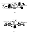
- Fig.1 illustrates two access modes in the VPN technologies: a remote access mode and a local access mode. Both modes access to the LANs in the VPN via the respective secure communication tunnels.
- the secure communication tunnel establishment methods and the shortages thereof in the two access modes will be briefly described below.
- the secure communication tunnel is often fixedly configured, that is, a secure tunnel is manually configured by a manager of the private LAN (VPN) in advance between a local point of presence and a remote access server.
- VPN private LAN
- the remote access server and the local point of presence are referred to as tunnel server.
- POP local point of presence
- the source host within the external network becomes possible to access to the private LAN in distance via the secure tunnel established in advance.
- the main shortages of the remote access mode lie in that: the secure tunnel is manually configured, so a lot of manually configuring jobs are required for VPN managers.
- networking components vary in the private LAN (VPN), for example, IP address is modified for the present remote access server/local point of presence, or a new remote access server/local point of presence is configured, etc., such statically configured manual tunnels need to be manually modified, which will become complicated.
- VPN private LAN
- the local access mode when a source host within the external network is about to access to the private LAN (VPN), it is first directly connected to a local access server to be accessed to in a local private LAN.
- the source host within the external network needs to be aware of an IP address of a corresponding local access server.
- a secure communication tunnel is established through negotiation between the local access server and the source host within the external network.
- the source host within the external network becomes possible to access to the private LAN in local via the tunnel.
- the roles of the tunnel servers are played by the local access servers and the source hosts within the external network.
- the main shortages of the local access mode lie in that: the tunnel is not transparent with respect to the subscribers.
- the subscribers are required to provide an IP address for the access servers with respect to corresponding private LANs.
- the subscribers need to keep in memory a lot of addresses for the access servers, which will increase the burden and difficulty of the subscribers using VPN.
- neither of the above two kinds of tunnel establishment methods supports subscriber devices of a small scale. All the hosts in the external network that are used to access to the private LANs participate in establishment procedures of secure communication tunnels to different extents. Especially for the local access mode, the hosts within the external network serve as tunnel servers to be directly in charge of the negotiation and establishment of the secure communication tunnels, which requires those hosts to install therein a tunnel support software that is complicated. In several circumstances, however, the devices that the subscribers use to access to the private LANs are likely to be quite simple in hardware and software, without such a tunnel support software installed or installable therein. As a result, the devices that the subscribers use to access to the private LANs will not be able to access to the private LANs via the secure tunnels.
- the present invention provides a dynamic tunnel establishment method that is novel.
- a source tunnel server or a destination tunnel server is disposed on a routing device through which a source host transmits IP data packets or a routing device through which a destination host receives IP data packets.
- a secure communication tunnel is established automatically rather than manually between the source and destination tunnel servers, without requiring any IP address to be provided for the access servers with respect to corresponding private LANs.
- the method of the present invention comprises the following steps:
- the device on the side of the source host intercepts and de-encrypts the IP data packet containing the tunnel negotiation command, and then generates an IP data packet containing a tunnel negotiation response command, which is subjected to encryption and subsequently transmitted to the device on the side of the destination host;
- the device on the side of the destination host intercepts and de-encrypts the IP data packet containing the tunnel negotiation response command.
- the device on the side of the destination host negotiates with the device on the side of the source host to establish a secure communication tunnel in accordance with tunnel parameters within the tunnel negotiation command.
- the device on the side of the above source host performing interception, de-encryption, generation, encryption and transmission of the IP data packets is a source tunnel server disposed on the path through which the source host receives/transmits IP data packets.
- the device on the side of the above destination host performing interception, de-encryption, generation, encryption and transmission of the IP data packets is a destination tunnel server disposed on the path through which the destination host receives/transmits IP data packets.
- the present invention also provides a tunnel server, wherein the tunnel server is either disposed on a path through which a source host within an external network receives/transmits IP data packets, to serve as a source tunnel server, or on a path through which a destination host within a private LAN receives/transmits IP data packets, to serve as a destination tunnel server, comprising:
- the source hosts within the external network need no configuration and process in relation to the negotiation and establishment of the secure communication tunnels. Therefor, there is no need to install those support software and hardware in relation to the negotiation and establishment of the secure communication tunnels. With the present method, those hosts relatively simply in software and hardware are also able to dynamically establish the secure communication tunnels for accessing to the private LANs.
- Fig.2 is a diagram of a systemic structure of a dynamic tunnel establishment method according to the first embodiment of the present invention. It is supposed for such a situation where a certain subscriber is one of the legal subscribers of private LAN A to which their companies pertain, who has been at other places than the local due to business trips or the other causes. There is a question, what to do for the subscriber to securely access to private LAN A if he/she needs to access to private LAN A, to which their companies pertain, to obtain essential materials therefrom.
- This mission requires the method of establishing dynamic tunnel of the present invention to establish a secure communication tunnel between the source host within the external network and the destination host within the private LAN, thereby the source host accessing to the destination host via the secure communication tunnel.
- Fig.2 illustrates a systemic structure, of the dynamic tunnel establishment method, in which one tunnel server is disposed on a path through which the source host within the external network receives/transmits IP data packets, to serve as a source tunnel server, while the other tunnel server is disposed on a path through which the destination host within the private LAN receives/transmits IP data packets, to serve as a destination tunnel server; an identity authenticating unit is disposed on a server within a public network to perform an identity authentication of a subscriber who is going to access to the private LAN. Thereafter, a secure communication tunnel becomes established between the source host and the destination host, thereby the source host accessing to the destination host via the secure communication tunnel.
- Fig.3 is a flow chart of a dynamic tunnel establishment method according to the second embodiment of the present invention.
- the source host within the external network transmits subscriber identity authentication information to the server to which the identity authenticating unit pertains, so as to perform the identity authentication at the identity authenticating unit (step 320).
- the subscriber identity authentication information includes subscriber name, subscriber password, IP address and port number of the destination host, and IP address of the source host.
- the step of the identity authenticating unit performing the identity authentication of the received identity authentication information further comprises the following steps:
- the destination tunnel server intercepts and processes the IP data packet containing the secure communication tunnel establishment command (step 340).
- the destination tunnel server intercepts the IP data packet containing tunnel commands in accordance with the methods derived from in-advance negotiations, and performs a de-encryption of the IP data packet, subsequently issues corresponding instruction in accordance with the contents of the tunnel command. Since the tunnel command described herein is to establish the secure communication tunnel, the destination tunnel server generates, in accordance with the instruction, an IP data packet containing a tunnel negotiation command, which is subjected to encryption and subsequently transmitted to the source tunnel server.
- the destination address of the IP data packet is IP address of the source host.
- the source tunnel server intercepts and processes the IP data packet containing the tunnel negotiation command (step 350).
- the source tunnel server intercepts the IP data packet containing the tunnel negotiation command in accordance with the methods derived from in-advance negotiations.
- the contents of the IP data packet containing the tunnel negotiation command include IP address of the source host, IP address and port number of the destination host, and parameters regarding the secure communication tunnel.
- the source tunnel server then performs a de-encryption of the IP data packet, and issues corresponding instruction in accordance with the contents of the tunnel command. Since the tunnel command described herein is to negotiate with respect to the secure communication tunnel, the source tunnel server generates, in accordance with the instruction, an IP data packet containing a tunnel negotiation response command, which is subjected to encryption and subsequent transmission to the destination tunnel server.
- the destination tunnel server intercepts and processes the IP data packet containing the tunnel negotiation response command (step 360).
- the destination tunnel server intercepts the IP data packet containing the tunnel command in accordance with the method derived from in-advance negotiations, and performs a de-encryption of the IP data packet, subsequently issues corresponding instruction in accordance with the contents of the tunnel command. Since the tunnel command described herein is the tunnel negotiation response command, when the tunnel command processing unit has determined it being accurate response command in accordance with the corresponding instruction, the tunnel negotiating module is called to enable the destination tunnel server to negotiate with the source tunnel server in accordance with the tunnel parameters within the tunnel negotiation command thereby to establish the secure communication tunnel.
- the destination tunnel server, the source tunnel server, or the server to which the identity authenticating unit pertains intercepts the IP data packet containing the tunnel command in accordance with the method derived from in-advance negotiations.
- the method may be flexibly designed. There rise two instances.
- SPI Security Parameter Index
- a stipulated reserved Security Parameter Index is placed into the header of the IP data packet as the Security Parameter Index (SPI) of the IP data packet, after encrypting the IP data packets containing tunnel commands at the party to which the identity authenticating unit pertains, a device on a side of the source host or a device on a side of the destination host.
- the source address a stipulated reserved address is used as the source address of the IP data packet, after encrypting the IP data packet containing tunnel command at the party to which the identity authenticating unit pertains, a device on a side of the source host or a device on a side of the destination host.
- the IP data packet is encrypted or de-encrypted, at the source tunnel server, the destination tunnel server, and the server to which the identity authenticating unit pertains, in accordance with security policies derived from their negotiation with each other and security unions corresponding to the security policies.
- the security policies and security unions are respectively stored in a security policy database and security union database that are those of the prior art.
- the source host within the external network becomes able to access to the destination host within the private LAN via the secure communication tunnel.
- the secure communication tunnel may be cancelled (step 370).
- this includes the following steps: the source host within the external network transmits the subscriber identity authentication information to the server to which the identity authenticating unit pertains. Thereafter, the server to which the identity authenticating unit pertains perform an identity authentication of the received information, upon having been subjected to the identity authentication, transmits an encrypted IP data packet containing a secure communication tunnel cancellation command to the destination tunnel server, wherein the destination addresses of the IP data packets are IP addresses of the destination hosts. Finally, the destination tunnel server issues a notification of cancelling the secure communication tunnel to the source tunnel server, and deletes tunnel parameters within the destination tunnel server.
- the identity authenticating unit is independently disposed on the server such as AAA server within the public network.
- the identity authenticating unit is allowed to have quite flexible dispositions, it can be either independently disposed on the other devices within the public network, or disposed on the destination tunnel server or the source tunnel server.
- Fig.4 is a block diagram of a tunnel server according to the second embodiment of the present invention.
- the tunnel server is disposed on a path through which a source host within the external network receives/transmits data packets, to serve as a source tunnel server, or on a path through which a destination host within the private LAN receives/transmits data packets, to serve as a destination tunnel server.
- a secure communication tunnel can be dynamically established between the source tunnel server and the destination tunnel server, and used to securely access to the private LAN.
- a tunnel server 400 comprises a tunnel negotiating unit 410, a tunnel data packet processing unit 420, a database 430, a tunnel command filtering unit 440, a tunnel command processing unit 450, and a tunnel command generating unit 460.
- the tunnel negotiating unit 410, the tunnel data packet processing unit 420, and the database 430 are normal modules of the tunnel server that belong to the prior art.
- the tunnel command filtering unit 440, the tunnel command processing unit 450, and the tunnel command generating unit 460 are newly added modules in the present invention. With these newly added modules, a secure communication tunnel can be dynamically established between the source tunnel server and the destination tunnel server, without any participation of the devices of the subscribers.
- the tunnel server addressing the network can be automatically completed without any manual configuration of the address information of the tunnel server.
- the tunnel negotiating unit 410 is used to negotiate with a tunnel server at an opposite end, with respect to encryption/de-encryption parameters of tunnels, in accordance with corresponding instructions.
- the tunnel negotiating unit 410 is normal model of tunnel server. "a tunnel server at an opposite end" described herein is in relation to the tunnel server 400. If the tunnel server 400 is a source tunnel server, the tunnel server at the opposite end is a destination tunnel server, vice versa.
- the tunnel data packet processing unit 420 is used to perform an encryption/de-encryption process of data packets transmitted via the secure communication tunnel in accordance with the encryption/de-encryption parameters of tunnels.
- the tunnel data packet processing unit 420 is a normal module of the tunnel server.
- the database 430 includes a security policy database for storing various kinds of security policies and a security union database for storing various kinds of security unions.
- the database 430 is a normal module of the tunnel server.
- the security policy (SP) and security union (SA) belong to a convention set up between two communication entities, for example, the source host within the external network and the destination host within the private LAN, for purposes of secure communications.
- the security policy is intended to determine whether outgoing or incoming IP data packet needs security assurances and protections, includes at least two optional symbols of the source and destination addresses of the IP data packets.
- the security policy further includes the other optional symbols of the source and destination ports or the like.
- Various kinds of security policies may be stored in the security policy database.
- the security union is intended to determine IPSec protocols, encryption manners, secret keys, and effective duration of the secret keys or the like for the security assurances and protections of the IP data packets.
- various kinds of security union may be stored in the security union database. The correspondence between the security policy and the security union belongs to the prior art.
- the tunnel command filtering unit 440 is used to intercept the IP data packet containing tunnel commands from the external network. There may be a plurality of flexible approaches for the tunnel command filtering unit 440 to intercept the IP data packet containing tunnel commands. For the details, refer to the description of the first embodiment. Such details are no longer repeated for the present embodiment.
- the tunnel command processing unit 450 is used to perform a de-encryption of the IP data packet containing the tunnel commands that is intercepted by the tunnel command filtering unit, and to issue corresponding instructions to the tunnel negotiating unit 410 or the tunnel command generating unit 460 in accordance with the contents of the tunnel commands. If the tunnel command is a secure communication tunnel establishment command, the tunnel command processing unit 450 issues an instruction to the tunnel command generating unit 460 to generate and transmit a secure communication tunnel negotiation command. If the tunnel command is a secure communication tunnel negotiation command, the tunnel command processing unit 450 issues an instruction to the tunnel command generating unit 460 to generate and transmit a secure communication tunnel negotiation response command. If the tunnel command is a secure communication tunnel negotiation response command, the tunnel command processing unit 450 issues an instruction to the tunnel negotiating unit 410 to negotiate with the tunnel server at the opposite end with respect to encryption/de-encryption parameters.
- the tunnel command generating unit 460 is used to generate corresponding tunnel commands in accordance with the instructions from the tunnel command processing unit 450 so as to perform an encryption of the tunnel commands and then transmit it to a destination address.
- the corresponding tunnel commands described herein include tunnel establishment commands, tunnel negotiation commands, tunnel negotiation response commands, or tunnel cancellation commands. If the tunnel command generating unit 460 is a tunnel command generating unit within the destination tunnel server, it generates the tunnel commands including tunnel establishment commands (if the identity authenticating unit is disposed within the destination tunnel server), tunnel negotiation commands, and tunnel cancellation commands. If the tunnel command generating unit 460 is a tunnel command generating unit within the source tunnel server, it generates the tunnel commands including tunnel negotiation response commands.
- the tunnel server 400 may further include an identity authenticating unit 470 that is used to perform an identity authentication of the source host within the external network.
- the identity authenticating unit 470 acquires from an AAA server within the public network a network address range of the private LANs corresponding to the subscriber name in accordance with the identity authentication information transmitted from the source host within the external network.
- the identity authentication information includes subscriber names, subscriber passwords, IP addresses and port numbers of the destination hosts, and IP addresses of the source hosts. Thereafter, the identity authenticating unit 470 checks whether or not the subscriber name and password belong to legal subscribers of the private LAN and whether or not the destination host to be subjected to access belongs to the private LAN. If it has been checked that the subscriber is one of legal subscribers, this subscriber is entitled to access to the private LAN.
- AAA Authentication, Authorization, Accounting
- the identity authenticating unit 470 may be disposed in other places than within the tunnel server 400.
- the identity authentication processing unit 470 may flexibly undergo an independent disposition on the servers (such as AAA servers) within the public network, instead of the restricted disposition on the tunnel servers.
- the next description is presented in detail with regard to the encryption or de-encryption performed on the IP data packet.
- the IP data packet is subjected to encryption/de-encryption process at the source tunnel server and the destination tunnel server in accordance with the security policies derived from their negotiation with each other and the security unions corresponding to the security policies.
- the security policies and the security unions are stored in the security policy & security union database, such a database belongs to the prior art.
- the security policy & security union database is included in the database 430.
- connection are indicated by imaginary lines with two reversible arrows between the database 430 and the tunnel negotiating unit 410, tunnel data packet processing unit 420, tunnel command processing unit 450, or tunnel command generating unit 460, to illustrate the interaction of data between the database 430 and the above units.
- the database 430 is always called when the above units need to encrypt/de-encrypt the IP data packets.
Landscapes
- Engineering & Computer Science (AREA)
- Computer Hardware Design (AREA)
- Computer Security & Cryptography (AREA)
- Computing Systems (AREA)
- General Engineering & Computer Science (AREA)
- Computer Networks & Wireless Communication (AREA)
- Signal Processing (AREA)
- Data Exchanges In Wide-Area Networks (AREA)
- Small-Scale Networks (AREA)
- Mobile Radio Communication Systems (AREA)
Applications Claiming Priority (1)
| Application Number | Priority Date | Filing Date | Title |
|---|---|---|---|
| CN2005100305246A CN1949705B (zh) | 2005-10-14 | 2005-10-14 | 一种用于安全访问专用局域网的动态隧道构建方法及用于该方法的装置 |
Publications (3)
| Publication Number | Publication Date |
|---|---|
| EP1775903A2 true EP1775903A2 (fr) | 2007-04-18 |
| EP1775903A3 EP1775903A3 (fr) | 2008-03-19 |
| EP1775903B1 EP1775903B1 (fr) | 2011-04-13 |
Family
ID=37667489
Family Applications (1)
| Application Number | Title | Priority Date | Filing Date |
|---|---|---|---|
| EP06021530A Not-in-force EP1775903B1 (fr) | 2005-10-14 | 2006-10-13 | Méthode et dispositif dynamique de construction d'un tunnel donnant accès sécurisé à un LAN privé |
Country Status (5)
| Country | Link |
|---|---|
| US (1) | US20070086462A1 (fr) |
| EP (1) | EP1775903B1 (fr) |
| CN (1) | CN1949705B (fr) |
| AT (1) | ATE505892T1 (fr) |
| DE (1) | DE602006021266D1 (fr) |
Cited By (1)
| Publication number | Priority date | Publication date | Assignee | Title |
|---|---|---|---|---|
| CN101682656B (zh) * | 2007-05-09 | 2013-07-24 | 艾利森电话股份有限公司 | 用于保护数据分组的路由选择的方法和设备 |
Families Citing this family (10)
| Publication number | Priority date | Publication date | Assignee | Title |
|---|---|---|---|---|
| CN101399665B (zh) * | 2007-09-24 | 2011-07-13 | 上海贝尔阿尔卡特股份有限公司 | 以基于身份的密码体制为基础的业务认证方法和系统 |
| US7975294B2 (en) * | 2007-11-19 | 2011-07-05 | International Business Machines Corporation | VPN management |
| JP2010034860A (ja) * | 2008-07-29 | 2010-02-12 | Fujitsu Ltd | セキュリティ機能を有するipネットワーク通信方法及び通信システム |
| US9083587B2 (en) * | 2009-08-21 | 2015-07-14 | Cisco Technology, Inc. | Port chunk allocation in network address translation |
| CN102420740B (zh) * | 2010-09-28 | 2015-06-10 | 中兴通讯股份有限公司 | 用于路由协议的密钥管理方法和系统 |
| CN103237015B (zh) * | 2013-03-29 | 2016-08-31 | 汉柏科技有限公司 | 一种IPSec安全关联存储方法 |
| CN104753752B (zh) * | 2013-12-30 | 2019-05-07 | 格尔软件股份有限公司 | 一种适用于vpn的按需连接方法 |
| US11290425B2 (en) * | 2016-02-01 | 2022-03-29 | Airwatch Llc | Configuring network security based on device management characteristics |
| CN106936684A (zh) * | 2017-01-18 | 2017-07-07 | 北京华夏创新科技有限公司 | 一种透明模式下无ip地址建立隧道的方法及系统 |
| CN114389916B (zh) * | 2022-01-20 | 2023-12-15 | 迈普通信技术股份有限公司 | 一种组网通信方法、装置、系统及网络设备 |
Citations (2)
| Publication number | Priority date | Publication date | Assignee | Title |
|---|---|---|---|---|
| US20030188001A1 (en) | 2002-03-27 | 2003-10-02 | Eisenberg Alfred J. | System and method for traversing firewalls, NATs, and proxies with rich media communications and other application protocols |
| EP1411676A1 (fr) | 2002-10-17 | 2004-04-21 | Alcatel | Méthode, serveur d'accès réseau, client et programme d'ordinateur pour la définition de connexions de tunnels de niveau 2 |
Family Cites Families (8)
| Publication number | Priority date | Publication date | Assignee | Title |
|---|---|---|---|---|
| US6076168A (en) * | 1997-10-03 | 2000-06-13 | International Business Machines Corporation | Simplified method of configuring internet protocol security tunnels |
| US6055236A (en) * | 1998-03-05 | 2000-04-25 | 3Com Corporation | Method and system for locating network services with distributed network address translation |
| US6522880B1 (en) * | 2000-02-28 | 2003-02-18 | 3Com Corporation | Method and apparatus for handoff of a connection between network devices |
| US6763018B1 (en) * | 2000-11-30 | 2004-07-13 | 3Com Corporation | Distributed protocol processing and packet forwarding using tunneling protocols |
| US6950862B1 (en) * | 2001-05-07 | 2005-09-27 | 3Com Corporation | System and method for offloading a computational service on a point-to-point communication link |
| US20040088385A1 (en) * | 2002-11-01 | 2004-05-06 | Hexago Inc. | Method and apparatus for connecting IPV4 devices through an IPV6 network using a tunnel setup protocol |
| ATE440467T1 (de) * | 2004-06-24 | 2009-09-15 | Spyder Navigations Llc | Transfer von paketdaten in einem system mit mobilendgerät, drahtlosem lokalem netzwerk und mobilnetzwerk |
| US20060251101A1 (en) * | 2005-04-25 | 2006-11-09 | Zhang Li J | Tunnel establishment |
-
2005
- 2005-10-14 CN CN2005100305246A patent/CN1949705B/zh not_active Expired - Lifetime
-
2006
- 2006-10-12 US US11/546,326 patent/US20070086462A1/en not_active Abandoned
- 2006-10-13 DE DE602006021266T patent/DE602006021266D1/de active Active
- 2006-10-13 EP EP06021530A patent/EP1775903B1/fr not_active Not-in-force
- 2006-10-13 AT AT06021530T patent/ATE505892T1/de not_active IP Right Cessation
Patent Citations (2)
| Publication number | Priority date | Publication date | Assignee | Title |
|---|---|---|---|---|
| US20030188001A1 (en) | 2002-03-27 | 2003-10-02 | Eisenberg Alfred J. | System and method for traversing firewalls, NATs, and proxies with rich media communications and other application protocols |
| EP1411676A1 (fr) | 2002-10-17 | 2004-04-21 | Alcatel | Méthode, serveur d'accès réseau, client et programme d'ordinateur pour la définition de connexions de tunnels de niveau 2 |
Cited By (1)
| Publication number | Priority date | Publication date | Assignee | Title |
|---|---|---|---|---|
| CN101682656B (zh) * | 2007-05-09 | 2013-07-24 | 艾利森电话股份有限公司 | 用于保护数据分组的路由选择的方法和设备 |
Also Published As
| Publication number | Publication date |
|---|---|
| US20070086462A1 (en) | 2007-04-19 |
| CN1949705B (zh) | 2010-08-18 |
| CN1949705A (zh) | 2007-04-18 |
| ATE505892T1 (de) | 2011-04-15 |
| EP1775903B1 (fr) | 2011-04-13 |
| DE602006021266D1 (de) | 2011-05-26 |
| EP1775903A3 (fr) | 2008-03-19 |
Similar Documents
| Publication | Publication Date | Title |
|---|---|---|
| US11190489B2 (en) | Methods and systems for establishing a connection between a first device and a second device across a software-defined perimeter | |
| US8239531B1 (en) | Method and apparatus for connection to virtual private networks for secure transactions | |
| US7661131B1 (en) | Authentication of tunneled connections | |
| JP4648148B2 (ja) | 接続支援装置 | |
| US8549157B2 (en) | Transparent secure socket layer | |
| US5835726A (en) | System for securing the flow of and selectively modifying packets in a computer network | |
| US12250199B2 (en) | Enhanced privacy preserving access to a VPN service | |
| US10425384B1 (en) | Optimizing connections over virtual private networks | |
| US7565526B1 (en) | Three component secure tunnel | |
| US8886934B2 (en) | Authorizing physical access-links for secure network connections | |
| WO1997000471A2 (fr) | Systeme pour la securisation et la modification selective du flux de paquets dans un reseau informatique | |
| US7707628B2 (en) | Network system, internal server, terminal device, storage medium and packet relay method | |
| US20040243837A1 (en) | Process and communication equipment for encrypting e-mail traffic between mail domains of the internet | |
| US20020178356A1 (en) | Method for setting up secure connections | |
| EP1775903B1 (fr) | Méthode et dispositif dynamique de construction d'un tunnel donnant accès sécurisé à un LAN privé | |
| Chawla et al. | A review on IPsec and SSL VPN | |
| JP3847343B2 (ja) | コンピュータネットワークにおける通信のセキュリティのためのデータパケットを検査し選択的変更を施す方法及びシステム及びそのシステムの操作方法 | |
| US20090271852A1 (en) | System and Method for Distributing Enduring Credentials in an Untrusted Network Environment | |
| Sharma | Secure remote access ipsec virtual private network to university network system | |
| US20050086533A1 (en) | Method and apparatus for providing secure communication | |
| JP4630296B2 (ja) | ゲートウェイ装置および認証処理方法 | |
| KR102059150B1 (ko) | IPsec 가상 사설 네트워크 시스템 | |
| Есенжолов et al. | Implementation of traffic protection based on ipsec vpn technology and network modeling on ensp software environment | |
| Degefa | VPN Scenarios, Configuration and Analysis:- | |
| TR2024017238A2 (tr) | Siber dünyadan zaafiyet taramasına ve sömürülmeye kapalı SSLVPN dizayn ve ürün |
Legal Events
| Date | Code | Title | Description |
|---|---|---|---|
| PUAI | Public reference made under article 153(3) epc to a published international application that has entered the european phase |
Free format text: ORIGINAL CODE: 0009012 |
|
| AK | Designated contracting states |
Kind code of ref document: A2 Designated state(s): AT BE BG CH CY CZ DE DK EE ES FI FR GB GR HU IE IS IT LI LT LU LV MC NL PL PT RO SE SI SK TR |
|
| AX | Request for extension of the european patent |
Extension state: AL BA HR MK YU |
|
| RIN1 | Information on inventor provided before grant (corrected) |
Inventor name: YAN, RENXIANG Inventor name: WEN, HAIBO Inventor name: ZHANG, QINGSHAN Inventor name: BIN, FANGXIANG |
|
| PUAL | Search report despatched |
Free format text: ORIGINAL CODE: 0009013 |
|
| AK | Designated contracting states |
Kind code of ref document: A3 Designated state(s): AT BE BG CH CY CZ DE DK EE ES FI FR GB GR HU IE IS IT LI LT LU LV MC NL PL PT RO SE SI SK TR |
|
| AX | Request for extension of the european patent |
Extension state: AL BA HR MK YU |
|
| RIC1 | Information provided on ipc code assigned before grant |
Ipc: H04L 12/46 20060101ALI20080212BHEP Ipc: H04L 12/22 20060101ALI20080212BHEP Ipc: H04L 29/06 20060101AFI20070126BHEP |
|
| 17P | Request for examination filed |
Effective date: 20080514 |
|
| 17Q | First examination report despatched |
Effective date: 20080625 |
|
| AKX | Designation fees paid |
Designated state(s): AT BE BG CH CY CZ DE DK EE ES FI FR GB GR HU IE IS IT LI LT LU LV MC NL PL PT RO SE SI SK TR |
|
| GRAP | Despatch of communication of intention to grant a patent |
Free format text: ORIGINAL CODE: EPIDOSNIGR1 |
|
| GRAS | Grant fee paid |
Free format text: ORIGINAL CODE: EPIDOSNIGR3 |
|
| GRAA | (expected) grant |
Free format text: ORIGINAL CODE: 0009210 |
|
| AK | Designated contracting states |
Kind code of ref document: B1 Designated state(s): AT BE BG CH CY CZ DE DK EE ES FI FR GB GR HU IE IS IT LI LT LU LV MC NL PL PT RO SE SI SK TR |
|
| REG | Reference to a national code |
Ref country code: GB Ref legal event code: FG4D |
|
| REG | Reference to a national code |
Ref country code: CH Ref legal event code: EP |
|
| REG | Reference to a national code |
Ref country code: IE Ref legal event code: FG4D |
|
| REF | Corresponds to: |
Ref document number: 602006021266 Country of ref document: DE Date of ref document: 20110526 Kind code of ref document: P |
|
| REG | Reference to a national code |
Ref country code: DE Ref legal event code: R096 Ref document number: 602006021266 Country of ref document: DE Effective date: 20110526 |
|
| REG | Reference to a national code |
Ref country code: NL Ref legal event code: VDEP Effective date: 20110413 |
|
| LTIE | Lt: invalidation of european patent or patent extension |
Effective date: 20110413 |
|
| PG25 | Lapsed in a contracting state [announced via postgrant information from national office to epo] |
Ref country code: LT Free format text: LAPSE BECAUSE OF FAILURE TO SUBMIT A TRANSLATION OF THE DESCRIPTION OR TO PAY THE FEE WITHIN THE PRESCRIBED TIME-LIMIT Effective date: 20110413 Ref country code: PT Free format text: LAPSE BECAUSE OF FAILURE TO SUBMIT A TRANSLATION OF THE DESCRIPTION OR TO PAY THE FEE WITHIN THE PRESCRIBED TIME-LIMIT Effective date: 20110816 Ref country code: SE Free format text: LAPSE BECAUSE OF FAILURE TO SUBMIT A TRANSLATION OF THE DESCRIPTION OR TO PAY THE FEE WITHIN THE PRESCRIBED TIME-LIMIT Effective date: 20110413 |
|
| PG25 | Lapsed in a contracting state [announced via postgrant information from national office to epo] |
Ref country code: ES Free format text: LAPSE BECAUSE OF FAILURE TO SUBMIT A TRANSLATION OF THE DESCRIPTION OR TO PAY THE FEE WITHIN THE PRESCRIBED TIME-LIMIT Effective date: 20110724 Ref country code: AT Free format text: LAPSE BECAUSE OF FAILURE TO SUBMIT A TRANSLATION OF THE DESCRIPTION OR TO PAY THE FEE WITHIN THE PRESCRIBED TIME-LIMIT Effective date: 20110413 Ref country code: CY Free format text: LAPSE BECAUSE OF FAILURE TO SUBMIT A TRANSLATION OF THE DESCRIPTION OR TO PAY THE FEE WITHIN THE PRESCRIBED TIME-LIMIT Effective date: 20110413 Ref country code: FI Free format text: LAPSE BECAUSE OF FAILURE TO SUBMIT A TRANSLATION OF THE DESCRIPTION OR TO PAY THE FEE WITHIN THE PRESCRIBED TIME-LIMIT Effective date: 20110413 Ref country code: SI Free format text: LAPSE BECAUSE OF FAILURE TO SUBMIT A TRANSLATION OF THE DESCRIPTION OR TO PAY THE FEE WITHIN THE PRESCRIBED TIME-LIMIT Effective date: 20110413 Ref country code: IS Free format text: LAPSE BECAUSE OF FAILURE TO SUBMIT A TRANSLATION OF THE DESCRIPTION OR TO PAY THE FEE WITHIN THE PRESCRIBED TIME-LIMIT Effective date: 20110813 Ref country code: GR Free format text: LAPSE BECAUSE OF FAILURE TO SUBMIT A TRANSLATION OF THE DESCRIPTION OR TO PAY THE FEE WITHIN THE PRESCRIBED TIME-LIMIT Effective date: 20110714 Ref country code: LV Free format text: LAPSE BECAUSE OF FAILURE TO SUBMIT A TRANSLATION OF THE DESCRIPTION OR TO PAY THE FEE WITHIN THE PRESCRIBED TIME-LIMIT Effective date: 20110413 Ref country code: BE Free format text: LAPSE BECAUSE OF FAILURE TO SUBMIT A TRANSLATION OF THE DESCRIPTION OR TO PAY THE FEE WITHIN THE PRESCRIBED TIME-LIMIT Effective date: 20110413 |
|
| PG25 | Lapsed in a contracting state [announced via postgrant information from national office to epo] |
Ref country code: NL Free format text: LAPSE BECAUSE OF FAILURE TO SUBMIT A TRANSLATION OF THE DESCRIPTION OR TO PAY THE FEE WITHIN THE PRESCRIBED TIME-LIMIT Effective date: 20110413 |
|
| PG25 | Lapsed in a contracting state [announced via postgrant information from national office to epo] |
Ref country code: CZ Free format text: LAPSE BECAUSE OF FAILURE TO SUBMIT A TRANSLATION OF THE DESCRIPTION OR TO PAY THE FEE WITHIN THE PRESCRIBED TIME-LIMIT Effective date: 20110413 Ref country code: EE Free format text: LAPSE BECAUSE OF FAILURE TO SUBMIT A TRANSLATION OF THE DESCRIPTION OR TO PAY THE FEE WITHIN THE PRESCRIBED TIME-LIMIT Effective date: 20110413 |
|
| PLBE | No opposition filed within time limit |
Free format text: ORIGINAL CODE: 0009261 |
|
| STAA | Information on the status of an ep patent application or granted ep patent |
Free format text: STATUS: NO OPPOSITION FILED WITHIN TIME LIMIT |
|
| RAP2 | Party data changed (patent owner data changed or rights of a patent transferred) |
Owner name: ALCATEL LUCENT |
|
| PG25 | Lapsed in a contracting state [announced via postgrant information from national office to epo] |
Ref country code: PL Free format text: LAPSE BECAUSE OF FAILURE TO SUBMIT A TRANSLATION OF THE DESCRIPTION OR TO PAY THE FEE WITHIN THE PRESCRIBED TIME-LIMIT Effective date: 20110413 Ref country code: SK Free format text: LAPSE BECAUSE OF FAILURE TO SUBMIT A TRANSLATION OF THE DESCRIPTION OR TO PAY THE FEE WITHIN THE PRESCRIBED TIME-LIMIT Effective date: 20110413 Ref country code: DK Free format text: LAPSE BECAUSE OF FAILURE TO SUBMIT A TRANSLATION OF THE DESCRIPTION OR TO PAY THE FEE WITHIN THE PRESCRIBED TIME-LIMIT Effective date: 20110413 Ref country code: RO Free format text: LAPSE BECAUSE OF FAILURE TO SUBMIT A TRANSLATION OF THE DESCRIPTION OR TO PAY THE FEE WITHIN THE PRESCRIBED TIME-LIMIT Effective date: 20110413 |
|
| REG | Reference to a national code |
Ref country code: CH Ref legal event code: PCOW Free format text: ALCATEL LUCENT;3, AVENUE OCTAVE GREARD;75007 PARIS (FR) |
|
| 26N | No opposition filed |
Effective date: 20120116 |
|
| REG | Reference to a national code |
Ref country code: DE Ref legal event code: R097 Ref document number: 602006021266 Country of ref document: DE Effective date: 20120116 |
|
| PG25 | Lapsed in a contracting state [announced via postgrant information from national office to epo] |
Ref country code: IT Free format text: LAPSE BECAUSE OF FAILURE TO SUBMIT A TRANSLATION OF THE DESCRIPTION OR TO PAY THE FEE WITHIN THE PRESCRIBED TIME-LIMIT Effective date: 20110413 Ref country code: MC Free format text: LAPSE BECAUSE OF NON-PAYMENT OF DUE FEES Effective date: 20111031 |
|
| REG | Reference to a national code |
Ref country code: CH Ref legal event code: PL |
|
| PG25 | Lapsed in a contracting state [announced via postgrant information from national office to epo] |
Ref country code: CH Free format text: LAPSE BECAUSE OF NON-PAYMENT OF DUE FEES Effective date: 20111031 Ref country code: LI Free format text: LAPSE BECAUSE OF NON-PAYMENT OF DUE FEES Effective date: 20111031 |
|
| REG | Reference to a national code |
Ref country code: IE Ref legal event code: MM4A |
|
| PG25 | Lapsed in a contracting state [announced via postgrant information from national office to epo] |
Ref country code: IE Free format text: LAPSE BECAUSE OF NON-PAYMENT OF DUE FEES Effective date: 20111013 |
|
| PG25 | Lapsed in a contracting state [announced via postgrant information from national office to epo] |
Ref country code: LU Free format text: LAPSE BECAUSE OF NON-PAYMENT OF DUE FEES Effective date: 20111013 |
|
| PG25 | Lapsed in a contracting state [announced via postgrant information from national office to epo] |
Ref country code: BG Free format text: LAPSE BECAUSE OF FAILURE TO SUBMIT A TRANSLATION OF THE DESCRIPTION OR TO PAY THE FEE WITHIN THE PRESCRIBED TIME-LIMIT Effective date: 20110713 |
|
| PG25 | Lapsed in a contracting state [announced via postgrant information from national office to epo] |
Ref country code: TR Free format text: LAPSE BECAUSE OF FAILURE TO SUBMIT A TRANSLATION OF THE DESCRIPTION OR TO PAY THE FEE WITHIN THE PRESCRIBED TIME-LIMIT Effective date: 20110413 |
|
| PG25 | Lapsed in a contracting state [announced via postgrant information from national office to epo] |
Ref country code: HU Free format text: LAPSE BECAUSE OF FAILURE TO SUBMIT A TRANSLATION OF THE DESCRIPTION OR TO PAY THE FEE WITHIN THE PRESCRIBED TIME-LIMIT Effective date: 20110413 |
|
| REG | Reference to a national code |
Ref country code: FR Ref legal event code: GC Effective date: 20131018 |
|
| REG | Reference to a national code |
Ref country code: FR Ref legal event code: RG Effective date: 20141016 |
|
| REG | Reference to a national code |
Ref country code: FR Ref legal event code: PLFP Year of fee payment: 10 |
|
| REG | Reference to a national code |
Ref country code: FR Ref legal event code: PLFP Year of fee payment: 11 |
|
| REG | Reference to a national code |
Ref country code: FR Ref legal event code: PLFP Year of fee payment: 12 |
|
| REG | Reference to a national code |
Ref country code: FR Ref legal event code: PLFP Year of fee payment: 13 |
|
| PGFP | Annual fee paid to national office [announced via postgrant information from national office to epo] |
Ref country code: FR Payment date: 20180913 Year of fee payment: 13 |
|
| PG25 | Lapsed in a contracting state [announced via postgrant information from national office to epo] |
Ref country code: FR Free format text: LAPSE BECAUSE OF NON-PAYMENT OF DUE FEES Effective date: 20191031 |
|
| REG | Reference to a national code |
Ref country code: DE Ref legal event code: R079 Ref document number: 602006021266 Country of ref document: DE Free format text: PREVIOUS MAIN CLASS: H04L0029060000 Ipc: H04L0065000000 |
|
| PGFP | Annual fee paid to national office [announced via postgrant information from national office to epo] |
Ref country code: GB Payment date: 20210831 Year of fee payment: 16 |
|
| PGFP | Annual fee paid to national office [announced via postgrant information from national office to epo] |
Ref country code: DE Payment date: 20210831 Year of fee payment: 16 |
|
| REG | Reference to a national code |
Ref country code: DE Ref legal event code: R119 Ref document number: 602006021266 Country of ref document: DE |
|
| GBPC | Gb: european patent ceased through non-payment of renewal fee |
Effective date: 20221013 |
|
| PG25 | Lapsed in a contracting state [announced via postgrant information from national office to epo] |
Ref country code: DE Free format text: LAPSE BECAUSE OF NON-PAYMENT OF DUE FEES Effective date: 20230503 |
|
| PG25 | Lapsed in a contracting state [announced via postgrant information from national office to epo] |
Ref country code: GB Free format text: LAPSE BECAUSE OF NON-PAYMENT OF DUE FEES Effective date: 20221013 |