EP1776155B1 - System und verfahren zum selektiven beladen und verschliessen mehrerer implantierbarer bioresorbierbarer schläuche für radioaktive seeds - Google Patents
System und verfahren zum selektiven beladen und verschliessen mehrerer implantierbarer bioresorbierbarer schläuche für radioaktive seeds Download PDFInfo
- Publication number
- EP1776155B1 EP1776155B1 EP05804756A EP05804756A EP1776155B1 EP 1776155 B1 EP1776155 B1 EP 1776155B1 EP 05804756 A EP05804756 A EP 05804756A EP 05804756 A EP05804756 A EP 05804756A EP 1776155 B1 EP1776155 B1 EP 1776155B1
- Authority
- EP
- European Patent Office
- Prior art keywords
- tube
- loading
- implantable
- implantable bioresorbable
- bioresorbable
- Prior art date
- Legal status (The legal status is an assumption and is not a legal conclusion. Google has not performed a legal analysis and makes no representation as to the accuracy of the status listed.)
- Expired - Lifetime
Links
- 238000007789 sealing Methods 0.000 title claims abstract description 20
- 238000000034 method Methods 0.000 title claims description 45
- 125000006850 spacer group Chemical group 0.000 claims abstract description 37
- 238000010438 heat treatment Methods 0.000 claims description 27
- 238000002725 brachytherapy Methods 0.000 claims description 21
- 238000004806 packaging method and process Methods 0.000 claims description 18
- 238000011282 treatment Methods 0.000 claims description 18
- 239000000463 material Substances 0.000 claims description 7
- 238000010899 nucleation Methods 0.000 claims description 7
- 230000000717 retained effect Effects 0.000 claims description 4
- 230000000007 visual effect Effects 0.000 claims description 3
- 238000011179 visual inspection Methods 0.000 claims description 3
- 238000001816 cooling Methods 0.000 claims description 2
- 239000000155 melt Substances 0.000 claims description 2
- 238000002844 melting Methods 0.000 claims description 2
- 230000008018 melting Effects 0.000 claims description 2
- 238000012790 confirmation Methods 0.000 claims 1
- 230000001419 dependent effect Effects 0.000 claims 1
- 230000002285 radioactive effect Effects 0.000 abstract description 27
- 239000007943 implant Substances 0.000 description 14
- 230000005855 radiation Effects 0.000 description 11
- 206010028980 Neoplasm Diseases 0.000 description 8
- 238000003780 insertion Methods 0.000 description 8
- 230000037431 insertion Effects 0.000 description 8
- 210000001519 tissue Anatomy 0.000 description 7
- KDLHZDBZIXYQEI-UHFFFAOYSA-N Palladium Chemical compound [Pd] KDLHZDBZIXYQEI-UHFFFAOYSA-N 0.000 description 6
- 239000000969 carrier Substances 0.000 description 6
- 206010073306 Exposure to radiation Diseases 0.000 description 5
- 206010060862 Prostate cancer Diseases 0.000 description 5
- 208000000236 Prostatic Neoplasms Diseases 0.000 description 5
- 238000005520 cutting process Methods 0.000 description 5
- 230000005012 migration Effects 0.000 description 5
- 238000013508 migration Methods 0.000 description 5
- 230000008569 process Effects 0.000 description 5
- ZCYVEMRRCGMTRW-UHFFFAOYSA-N 7553-56-2 Chemical compound [I] ZCYVEMRRCGMTRW-UHFFFAOYSA-N 0.000 description 4
- 229920000642 polymer Polymers 0.000 description 4
- 238000012360 testing method Methods 0.000 description 4
- 210000000988 bone and bone Anatomy 0.000 description 3
- 210000000056 organ Anatomy 0.000 description 3
- 230000008901 benefit Effects 0.000 description 2
- 201000011510 cancer Diseases 0.000 description 2
- 229920001577 copolymer Polymers 0.000 description 2
- 230000000694 effects Effects 0.000 description 2
- 239000003999 initiator Substances 0.000 description 2
- 229910052740 iodine Inorganic materials 0.000 description 2
- 239000011630 iodine Substances 0.000 description 2
- 229910052751 metal Inorganic materials 0.000 description 2
- 239000002184 metal Substances 0.000 description 2
- 229910052763 palladium Inorganic materials 0.000 description 2
- 210000002307 prostate Anatomy 0.000 description 2
- 239000000523 sample Substances 0.000 description 2
- 238000002604 ultrasonography Methods 0.000 description 2
- 240000007594 Oryza sativa Species 0.000 description 1
- 235000007164 Oryza sativa Nutrition 0.000 description 1
- 229920000954 Polyglycolide Polymers 0.000 description 1
- RTAQQCXQSZGOHL-UHFFFAOYSA-N Titanium Chemical compound [Ti] RTAQQCXQSZGOHL-UHFFFAOYSA-N 0.000 description 1
- 235000013339 cereals Nutrition 0.000 description 1
- 230000006835 compression Effects 0.000 description 1
- 238000007906 compression Methods 0.000 description 1
- 239000013256 coordination polymer Substances 0.000 description 1
- 230000008878 coupling Effects 0.000 description 1
- 238000010168 coupling process Methods 0.000 description 1
- 238000005859 coupling reaction Methods 0.000 description 1
- 239000012297 crystallization seed Substances 0.000 description 1
- 230000001747 exhibiting effect Effects 0.000 description 1
- 238000007730 finishing process Methods 0.000 description 1
- 239000011521 glass Substances 0.000 description 1
- JVTAAEKCZFNVCJ-UHFFFAOYSA-N lactic acid Chemical class CC(O)C(O)=O JVTAAEKCZFNVCJ-UHFFFAOYSA-N 0.000 description 1
- 235000014655 lactic acid Nutrition 0.000 description 1
- 210000004072 lung Anatomy 0.000 description 1
- 238000004519 manufacturing process Methods 0.000 description 1
- 238000012986 modification Methods 0.000 description 1
- 230000004048 modification Effects 0.000 description 1
- 229910001120 nichrome Inorganic materials 0.000 description 1
- 229920003023 plastic Polymers 0.000 description 1
- 239000004033 plastic Substances 0.000 description 1
- 229920000747 poly(lactic acid) Polymers 0.000 description 1
- 229920002463 poly(p-dioxanone) polymer Polymers 0.000 description 1
- 239000000622 polydioxanone Substances 0.000 description 1
- 229920006149 polyester-amide block copolymer Polymers 0.000 description 1
- 239000004633 polyglycolic acid Substances 0.000 description 1
- 239000004626 polylactic acid Substances 0.000 description 1
- 235000009566 rice Nutrition 0.000 description 1
- 239000007787 solid Substances 0.000 description 1
- 238000006467 substitution reaction Methods 0.000 description 1
- 238000002560 therapeutic procedure Methods 0.000 description 1
- 239000010936 titanium Substances 0.000 description 1
- 229910052719 titanium Inorganic materials 0.000 description 1
- 238000012795 verification Methods 0.000 description 1
Images






Classifications
-
- A—HUMAN NECESSITIES
- A61—MEDICAL OR VETERINARY SCIENCE; HYGIENE
- A61N—ELECTROTHERAPY; MAGNETOTHERAPY; RADIATION THERAPY; ULTRASOUND THERAPY
- A61N5/00—Radiation therapy
- A61N5/10—X-ray therapy; Gamma-ray therapy; Particle-irradiation therapy
- A61N5/1001—X-ray therapy; Gamma-ray therapy; Particle-irradiation therapy using radiation sources introduced into or applied onto the body; brachytherapy
- A61N5/1007—Arrangements or means for the introduction of sources into the body
-
- A—HUMAN NECESSITIES
- A61—MEDICAL OR VETERINARY SCIENCE; HYGIENE
- A61N—ELECTROTHERAPY; MAGNETOTHERAPY; RADIATION THERAPY; ULTRASOUND THERAPY
- A61N5/00—Radiation therapy
- A61N5/10—X-ray therapy; Gamma-ray therapy; Particle-irradiation therapy
- A61N5/1001—X-ray therapy; Gamma-ray therapy; Particle-irradiation therapy using radiation sources introduced into or applied onto the body; brachytherapy
- A61N5/1007—Arrangements or means for the introduction of sources into the body
- A61N2005/1009—Apparatus for loading seeds into magazines or needles
-
- A—HUMAN NECESSITIES
- A61—MEDICAL OR VETERINARY SCIENCE; HYGIENE
- A61N—ELECTROTHERAPY; MAGNETOTHERAPY; RADIATION THERAPY; ULTRASOUND THERAPY
- A61N5/00—Radiation therapy
- A61N5/10—X-ray therapy; Gamma-ray therapy; Particle-irradiation therapy
- A61N5/1001—X-ray therapy; Gamma-ray therapy; Particle-irradiation therapy using radiation sources introduced into or applied onto the body; brachytherapy
- A61N2005/1019—Sources therefor
- A61N2005/1023—Means for creating a row of seeds, e.g. spacers
Definitions
- the present invention relates generally to radiation sources placed within a body for treating cancer and to holders/injectors for such radiation sources. More specifically, the present invention relates to methods and apparatus for a selectively loadable/sealable bioresorbable carrier assembly for low dose radioisotope seeds used in brachytherapy procedures.
- radioisotopes for various medical procedures such as brachytherapy and the like are well known. Such uses fall into two general categories: (i) high dose radioisotopes which are temporarily positioned in relation to a patient's body for a relatively short period of time to effect the radiation treatment, and (ii) low dose radioisotopes which are permanently implanted in a patient's body with the duration of the radiation treatment determined by the strength and half-life of the radioisotope being implanted.
- High dose radioisotopes are typically implanted using a catheter arrangement and a device commonly known as an afterloader that advances the high dose radioisotope located on the end of a source wire through the catheter to the desired location.
- Low dose radioisotopes are implanted using an array of implant needles with the low dose radioisotopes being encapsulated in very small containers known as seeds that are manually loaded into a series of implant needles and then ejected to form a three-dimensional grid of radioisotopes in the patient that corresponds to a dose plan as determined by the physician.
- the goal of the low dose brachytherapy procedure is to position this three-dimensional grid of radioisotopes seeds in and around a target cancerous tissue area.
- Each of the radioisotope seeds consists of a radioactive source such as Iodine (I-125) or Palladium (Pd-103) inside a small tube-like titanium shell that is about the size of a grain of rice.
- a radioactive source such as Iodine (I-125) or Palladium (Pd-103) inside a small tube-like titanium shell that is about the size of a grain of rice.
- These type of low dose radioactive sources emit a very low energy radiation that is primarily absorbed by the tissue immediately surrounding the radioisotope seed. This constant low energy radiation is typically emitted by the radioisotope seeds for a period of up to six months as a way to kill the cancer cells in the target area without having to subject the patient to the discomfort and risks that often accompany high dose radioisotope procedures.
- brachytherapy procedure is the use of low dose radioisotopes to treat prostate cancer.
- brachytherapy procedures using low dose radioisotopes can be applied to many different parts of the body, it is helpful to describe a particular treatment to gain a better understanding of these treatments.
- the typical prostate cancer brachytherapy procedure involves positioning a predetermined number of seeds (between 1-6) within each of a series of implant needles (up to 40), the seeds being spaced apart in each needle by small spacers.
- a small amount of bone wax is positioned on the tip of the implant needles to prevent the seeds and spacers from falling out until they are implanted in the patient.
- the loaded implant needles are then positioned at the appropriate location for insertion into the perineal area of the patient using a stand that has an X-Y coordinate grid. Each needle is manually positioned in the appropriate chamber in the grid and is inserted into the patient. An ultrasound probe is used to assist the physician in guiding each of the needles to the desired location.
- the seeds and spacers are delivered from the tip of the implant needle using a stylet and hollow needle arrangement where the hollow needle is preferably retracted while the stylet remains in place such that the seeds are forced out of the implant needle and such that the seeds occupy the space evacuated by the needle.
- the implanted seeds form a three-dimensional grid of radioisotope sources that implements a predetermined dose plan for treating the prostate cancer in the patient.
- a predetermined dose plan for treating the prostate cancer in the patient For a more detailed background of the procedures and equipment used in this type of prostate cancer treatment, reference is made to U.S. Patent Nos. 4,167,179 and 6,537,192 .
- the seeds and spacer are no longer held in position relative to one another and an opportunity exists for them to migrate within and possibly outside of the tumor.
- Potential migration of the radioactive seeds within the body leads to several issues. First, the time consuming step of properly positioning the needles using the ultrasound probe is defeated. Secondly, migration of seeds results in a deviation from the treatment program possibly causing some areas of cancerous tissue to be overexposed to radiation while others are underexposed. Finally, migration of the seeds outside of the tumor can lead to the seeds becoming lodged within healthy tissue or organs, for example the lungs. The healthy tissue or organ is then exposed to radiation, which will have undesired effects on healthy cells. All of these potential consequences can contribute to reducing the overall success of the brachytherapy procedure.
- Several methods for fixing the orientation of seeds and spacers include configurations in which the seeds and spacers are interlocked to create a unitary assembly, such as described in U.S. Patent No. 6,010,446 .
- the seeds and spacers are packaged in a carrier and subsequently placed into the tumor.
- these carriers are preloaded and shipped from an off-site location based on a treatment plan supplied by the treating physician.
- U.S. Patents Nos. 4,697,575 and 4,815,449 describe a bioresorbable elongated member that carries a fixed number of multiple radioisotopes seeds.
- U. S. Patent No. 5,460,592 describes a pre-loaded bioresorbable strand that is pre-loaded with ten seeds spaced at equal distances for use in a conventional metal implant needle and is commercially available under the Rapid Strand TM brand name.
- a physician uses a cutting jig during the brachytherapy procedure to cut each strand in order to provide the desired number of seeds to be loaded into the implant needle at a given treatment location.
- 6,450,937 and 6,530,875 describe needle arrangements that utilize open ended and translucent needle carrier tubes as part of the loading process to permit visual inspection of the arrangement of seeds and spacers to be loaded, however, these needle carrier tubes are not intended to be implanted as part of the brachytherapy procedure.
- WO2004/014215 which claims priority from a US Contnuation-in-part of US6,530,875 mentioned previously, discloses another embodiment of such a system wherein at least two seeds are secured together by a filament.
- U. S. Patent No. 6,679,824 describes a single stranded bioresorbable material that is preloaded with seeds by placing the seeds in slits made along the material and then preferably melting the material around each seed.
- the present invention is directed to a system for loading a selectable arrangement of radioactive seeds and spacers into a bioresorbable tube for use in brachytherapy procedures.
- the present invention is also directed to a method for loading a selectable arrangement of radioactive seeds and spacers into a bioresorbable tube for use in brachytherapy procedures.
- the selectively loadable/sealable bioresorbable carrier assembly comprises a bioresorbable tube having a closed distal end and a proximal open end.
- the bioresorbable tube is oriented with respect to a loading station such that a selectable arrangement of elements, including at least one radioactive seed, are loaded into the bioresorbable tube through the proximal open end. After the bioresorbable tube is selectably loaded, the bioresorbable tube is transferred to a finishing station that includes an automated heat source.
- the finishing station positions the bioresorbable tube based on the selectable arrangement of elements such that the automated heat source heat seals the bioresorbable tube at the proximal end of the selectable arrangement of elements. Once sealed, the bioresorbable tube maintains the arrangement of elements for the duration of therapy.
- the bioresorbable carrier assembly is configured such that an arrangement of radioactive seeds and spacer members can be selectively loaded at the treatment facility just prior to the brachytherapy procedure. Most preferably, the seeds and spacers are precisely loaded by an automated loading system.
- the bioresorbable carrier assembly of the present invention provides treatment flexibility to the medical professional that is unavailable with the preloaded needles and carriers currently in use. This flexibility allows the medical professional to selectively modify the treatment program based on observations made at the time of insertion.
- bioresorbable carrier system of the present invention eliminates the radiological testing and disposal issues present with preloaded carriers as seed potency can be determined prior to individual placement within the bioresorbable carrier thereby eliminating the need to remove and separately test individual seeds.
- an automated loading system the risk of radiation exposure to medical personnel is reduced through the use of an automated process to test seed potency and load the bioresorbable carrier.
- a selectable arrangement of elements including radioactive seeds and spacers are retained and positioned within a bioresorbable tube having a distal closed end, a proximal open end and lumen therebetween.
- the bioresorbable tube is constructed so as to allow the use of industry standard elements.
- the bioresorbable tube is constructed for use in conjunction with industry standard seeding needles.
- the bioresorbable carrier assembly of the present invention allows for physicians to precisely deliver a selectable arrangement of low dose radioisotope seeds and spacers into a tumor.
- a bioresorbable tube is automatically loaded and sealed using an automated loading machine.
- the bioresorbable carrier tube assembly of the present invention is described with reference to prostate brachytherapy treatment. It will be understood that the bioresorbable carrier assembly is contemplated for use in other brachytherapy procedures that benefit from the precise delivery and retainment of low dose radioisotope seeds within a tumor.
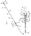
- an embodiment of a bioresorbable tube 100 of the present invention comprises a length of bioresorbable tubing.
- Bioresorbable tube 100 is comprised of a suitable bioresorbable polymer or copolymer, for example polymers or copolymers of polyglycolic acid, polylactic acid, polyester amides of glycolic or lactic acids, polydioxanone and the like. It will be understood that the length of time required for bioresorbable tube 100 to break down in the body is designed to be long enough to maintain the radioactive seeds and spaced in position for the intended duration of the brachytherapy.
- bioresorbable tube 100 comprises a commercially available polymer such as polyglactin 910, polyglycaprone 25 or polydioanone.
- Bioresorbable tube 100 is defined by a distal closed end 102, a proximal open end 104 and a lumen 106 therebetween.
- Lumen 106 defines a tube inside diameter 110 while a tube wall 108 defines a tube outside diameter 112.
- tube inside diameter 110 is .036 inches while the tube outside diameter 112 is .039 inches.
- Bioresorbable tube 100 is constructed such that the tube inside diameter 110 allows for loading commercially available radioactive seeds and spacers such as those manufactured by Mentor Corporation of Santa Barbara, California, within the lumen 106.
- Bioresorbable tube 100 is further constructed such that the tube outside diameter 112 allows the bioresorbable tube 100 to be loaded into commercially available seeding needles.
- Bioresorbable tube 100 has a tube length 113. In one embodiment, tube length 113 exceeds 70 mm.
- Bioresorbable tube 100 is preferably shipped as a component of a packaging kit 114 as depicted in Figs. 3 and 4 .
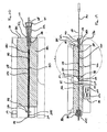
- the packaging kit 114 includes the bioresorbable tube 100, a loading stylet 116, a packaging tube 118, and a loading assembly 120.
- the packaging kit 114 allows a user to quickly confirm that all components have been received.
- the packaging kit 114 provides for immediate attachment to a loading means as described later without requiring any assembly or component manipulation.
- Loading assembly 120 as further depicted in Figs. 5 and 6 , comprises a loading tube 122 and a loading spring 124. As illustrated in Figs. 5, 6 and 7 , the loading assembly 120 and the loading stylet 116 are arranged in a loading orientation 126 described in more detail below.
- Loading stylet 116 comprises a rod 128 and a handle 130.
- Rod 128 is preferably a solid rod dimensioned to fit within the lumen 106.
- Rod 128 can be constructed of metallic or polymeric materials.
- Rod 128 is fixedly attached to the handle 130 at a stylet flange 132.
- Handle 130 includes a circumferential handle flange 133. In a preferred embodiment, handle 130 comprises a polymeric material molded over the rod 128.
- Loading tube 122 comprises a loading connector 134.
- Loading tube 122 further comprises a continuous loading tube lumen 136 having a tapered lumen portion 138.
- Tapered lumen portion 138 includes a circumferential loading spring channel 142.
- the loading tube lumen 136 defmes a continuous lumen between a loading end 146 and an unloading end 148.
- the proximal open end 104 of bioresorbable tube 100 is dimensioned to reside within the tapered lumen portion 138.
- a circumferential application of bone wax 149 in proximity to the proximal open end 104 as illustrated in Figs.
- Loading tube 122 also includes a circumferential alignment flange 152.
- Loading connector 134 is dimensioned and adapted for operable connection to a fitting such as a Luer lock or other comparable fitting.
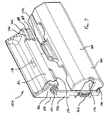
- a tube assembly apparatus 154 is shown in Figs. 7 , 8 and 9 .
- the tube assembly apparatus 154 comprises a frame member 156 having a mounting surface 158. Attached to frame member 156 is a loading station 160, a finishing station 162 and a power connector 164.
- tube assembly apparatus 154 is operably attached to an automated loader 166 as shown in Fig. 10 .
- An example of a suitable automated loader 166 is the IsoLoader® family of products manufactured by Mentor Corporation of Santa Barbara, California, and described in U. S. Patents Nos. 6,537,192 and 6,616,593 , as well as U. S. Patent Applications Nos.
- Loading station 160 comprises a hinged cover 168 attached to the frame member 156 at a hinge 170.
- Hinged cover 168 includes a handle 172 and defines a loading cavity 174. Loading cavity 174 is sized so as to fully accommodate the packaging kit 114.
- Hinged cover 168 is manufactured of a suitable radiation shielding material such as metal, lead-doped glass or suitable radiation absorbing plastic polymers.
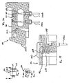
- Finishing station 162 comprises a positioning assembly 176, a heating assembly 178, a mounting assembly 180 and a shield 182 shown in Figs. 11 and 12 .
- Shield 182 can include a measuring scale 183 and a sealing mark 185.
- Finishing station 162 is generally defined by a tube insertion end 184 and a tube removal end 186.
- Positioning assembly 176 includes a loading tube channel 188 aligned with a finishing channel 190 to define a continuous channel 191 extending from the tube insertion end 184 to the tube removal end 186.
- Heating assembly 178 comprises a heating module 192 and a control module 194.
- Heating module 192 as shown in Figs. 13, 14 , 15, 16, 17 and 18 , comprises a heating frame 196, a heating element 198, a retaining latch 200, a latch pin 202, a pair of latch springs 204a, 204b, a pair of heater leads 206a, 206b and a positioning spring 208.
- Heating element 198 typically comprises a single length of nichrome wire, though other heating means exhibiting similar heating characteristics could be used.
- Heating frame 196 defines a heater cavity 210, a heater channel 212, a pin throughbore 214, a latch cavity 216 and a spring cavity 218.
- a spring opening 219 is located within heater channel 212.
- Control module 194 comprises a status indicator 220, such as a pair of LED's indicating a sealing status and a ready status, and a cycle initiator 222 such as a push-button or switch.
- Mounting assembly 180 comprises a mounting connector 224 aligned and coupled with the finishing channel 191.
- Mounting connector 224 can comprise a standard fastener such as a Luer lock.
- bioresorbable tube 100 is used to fixedly position radioactive seeds within the body during a brachytherapy procedure. Prior to placing the bioresorbable tube 100 within the body, bioresorbable tube 100 is loaded with radioactive seeds according to the desired treatment plan. In a preferred embodiment, bioresorbable tube 100 is loaded using the automated loader 166 which can incorporate a variety of testing and safety features to speed the loading of the bioresorbable tube 100. In an alternative embodiment, bioresorbable tube 100 is loaded via a manual loading process, for example hand loading with a tweezer. The bioresorbable tube 100 suitably retains and positions the radioactive seeds without regard as to the method of loading.
- the automated loader 166 is configured for operably mounting the tube assembly apparatus 154.
- the automated loader 166 is adapted to include a power supply for interfacing with the power connector 164 during coupling of the tube assembly apparatus 154 to the automated loader 166.
- the power connector 164 can be connected to a stand-alone cord and plug.
- the hinged cover 160 is rotatably opened such that the packaging kit 114 can be coupled to the automated loader 166.
- the bioresorbable tube 100 is positioned within the loading tube lumen 136.
- the hinged cover 168 is preferably rotated to a closed position such that the bioresorbable tube 100 within the packaging kit 114 is fully positioned within the loading cavity 174.
- the hinged cover 168 shields nearby personnel from potential radiation exposure during loading of the bioresorbable tube 100.
- Automated loader 166 includes insertion means for slidably inserting a selectable arrangement of elements comprising low dose radioactive seeds 226 and spacers 228 within the bioresorbable tube 100.
- automated loader 166 loads a minimum of at least one radioactive seed 226.
- Radioactive seeds 226 and spacers 228 can comprise any commercially available configuration having dimensions slightly less than the carrier tube inside diameter 110. Examples of suitable radioactive seeds 226 include Iodine (I-125) and Palladium (Pd-103) seeds manufactured by Mentor Corporation of Santa Barbara, California, with a seed length of approximately 4.5 mm and a seed diameter of approximately 0.8 mm.
- spacers 228 include Accu-Space TM and BioSpacer 910 TM spacers available from CP Medical of Portland, Oregon.
- Spacer 228 can be provided in various lengths, for example 5.5 mm or 10 mm, such that the positioning of radioactive seeds 226 can be conformed to the treatment plan.
- Automated loader 166 proceeds to load the bioresorbable tube 100 with the radioactive seeds 226 and spacers 228 as dictated by the treatment plan and as disclosed in the aforementioned and incorporated IsoLoader TM patents and published patent applications.
- the bioresorbable tube 100 can be loaded with any variety of radioactive seeds 226 and spacers 228 with the only limitation being that the loading arrangement not exceed 70 mm in length.
- the radioactive seeds 226 and spacers 228 are advanced into the bioresorbable tube 100 through the proximal open end 104 whereby they are advanced through the lumen 106 and whereby further advancement is prevented by distal closed end 102.
- the hinged cover 168 is rotatably opened as depicted in Fig. 10 such that the loading tube 122 can be removed from the automated loader 166.
- loading stylet 116 and packaging tube 118 are removed such that loading assembly 120 can be positioned with respect to the positioning assembly 176, as shown in Figs. 8 , 19 , 20 and 21 .
- Packaging tube 118 can be discarded while loading stylet 116 is set aside for use as described below.
- the loading tube 122 in positioning the loading assembly 120 with respect to the positioning assembly 176, the loading tube 122 is placed within the loading tube channel 188 and slidingly advanced until the circumferential alignment flange 152 is in contact with the tube insertion end 184. At this point, a portion of the loading tube lumen 136 including the bioresorbable tube 100 resides within the finishing channel 190. When the bioresorbable tube 100 is located within the finishing channel 190, the shield 182 prevents radiation exposure to a user during the finishing process.
- a user directs the rod 128 of loading stylet 116 into the tapered lumen portion 138 as depicted in Fig. 21 .
- the rod 128 is slidingly advanced through the tapered lumen portion 138 such that the rod 128 enters into the lumen 106 whereby the rod 128 comes into contact with a proximalmost element 230, i.e., a radioactive seed 226 or spacer 228.
- a proximalmost element 230 i.e., a radioactive seed 226 or spacer 228.
- the bioresorbable tube 100 is advanced out of the loading tube lumen 136 and into the finishing channel 190 due to the rod 128 pushing the combination of radioactive seeds 226 and spacers 228 against the distal closed end 102.
- the advancement of the rod 128 overcomes the retaining features, i.e., the proximal open end 104 and the bone wax 149, that previously acted to retain the bioresorbable tube 100 within the loading tube 122.
- the stylet flange 132 comes into contact with the loading spring 124 whereby further advancement of the rod 128 causes compression of the loading spring 124.
- Rod 128 is fully advanced until the circumferential handle flange 133 abuts the loading end 146. At this point, the user releases the handle 130 whereby the loading spring 124 relaxes such that the rod 128 is directed away from the rearmost element 230.
- loading spring 124 relaxes a distance of approximately 2 mm so as to create an approximately 2 mm gap between the rod 128 and the proximalmost element 230.
- Loading stylet 116, loading tube channel 188 and finishing channel 190 are precisely dimensioned such that when loading spring 124 relaxes, the heating element 198 is aligned within the approximately 2 mm gap between the rod 128 and the proximalmost element 230.
- the heating element 198 is properly positioned within the 2 mm gap without regard to the number or configuration of radioactive seeds 226 and spacers 228 loaded within the bioresorbable stand 100 as dictated by the treatment plan.
- the heating element 198 could be aligned with a special rearmost element 230 that is designed to melt as part of the heat sealing process.
- the user seals the lumen 106 at the 2 mm gap.
- the user presses or switches the cycle indicator 222 to initiate the sealing process.
- the cycle initiator 222 communicates with an internal microprocessor or electronic circuit integral to the heating assembly 178 such that the heater leads 206a, 206b are powered.
- the heater leads 206a, 206b cause the heating element 198 to quickly heat whereby the bioresorbable tube 100 melts within the 2 mm gap.
- the status indicator 220 provides a visual feedback, i.e., a light, indicating the heating condition.
- the heater leads 206a, 206b are typically powered from two to fifteen seconds to accommodate polymeric variations within bioresorbable carrier tubes 100 of differing manufacturing batches. Once the heating time is completed, the heater leads 206a, 206b are deenergized such that a newly formed, proximal sealed end 232 is allowed to cool. After cooling for approximately 3 seconds, the microprocessor or electronic circuit directs the status indicator 220 to indicate that a sealed tube 234 is complete.
- Second stylet 236 has a second stylet rod 238 with a length greater than the continuous channel 191.
- the user can attach a seeding needle 240 or alternative delivery vehicle to the mounting connector 224.
- the user advances the second stylet rod 238 through the continuous channel 191 whereby the second stylet rod 238 contacts the proximal sealed end 232 causing the sealed tube 234 to be advanced into the seeding needle 240.
- the seeding needle 240 is detached and ready for use in placing the sealed tube 234 within cancerous tissue.
Landscapes
- Health & Medical Sciences (AREA)
- Engineering & Computer Science (AREA)
- Biomedical Technology (AREA)
- Life Sciences & Earth Sciences (AREA)
- Nuclear Medicine, Radiotherapy & Molecular Imaging (AREA)
- Radiology & Medical Imaging (AREA)
- Pathology (AREA)
- Animal Behavior & Ethology (AREA)
- General Health & Medical Sciences (AREA)
- Public Health (AREA)
- Veterinary Medicine (AREA)
- Radiation-Therapy Devices (AREA)
- Prostheses (AREA)
- Medicines Containing Plant Substances (AREA)
Claims (22)
- System zum selektiven Laden und Versiegeln einer Vielzahl implantierbarer bioresorbierbarer Röhren (100) für niedrig dosierte radioisotopische Seeds, wobei jede der Vielzahl implantierbarer bioresorbierbarer Röhren (100) ein distales geschlossenes Ende (102) und ein proximales offenes Ende (104) und dazwischen ein Lumen (106) aufweist, und wobei das System Folgendes umfasst:eine Ladestation (160), die es einem Benutzer gestattet,eine auswählbare Anordnung von Elementen, die zumindest ein radioisotopisches Seed (226) enthält, durch das proximale offene Ende (104) jeder implantierbaren bioresorbierbaren Röhre (100) in das Lumen (106) zu laden; undeine Endbearbeitungsstation (162), die eine automatisierte Wärmequelle enthält, welche selektiv jede implantierbare bioresorbierbare Röhre (100) schmilzt und das proximale offene Ende (104) jeder implantierbaren bioresorbierbaren Röhre (100) an einer Versiegelungsposition entlang der bioresorbierbaren Röhre versiegelt, die im Allgemeinen so neben einem proximalen Ende der auswählbaren Anordnung von Elementen liegt, dass die auswählbare Anordnung von Elementen in der implantierbaren bioresorbierbaren Röhre (100) derart gehalten wird, dass sich die Versiegelungsposition für verschiedene der Vielzahl implantierbarer bioresorbierbarer Röhren (100) in verschiedenen Abständen zum distalen geschlossenen Ende (102) befindet, abhängig von der auswählbaren Anordnung von Elementen, die in diese implantierbare bioresorbierbare Röhre (100) eingebracht wird.
- System nach Anspruch 1, wobei die Ladestation (160) eine automatisierte Ladestation ist.
- System nach Anspruch 2, das des Weiteren eine Laderöhre (122) umfasst, die extern und koaxial zu jeder implantierbaren bioresorbierbaren Röhre ist und zwei offene Enden (146, 148) hat, mit einem Ladeadapter an einem Ende, der sich mit einer Öffnung an der automatisierten Ladestation verbindet.
- System nach Anspruch 3, wobei der Ladeadapter einen aufgeweiteten Teil der Laderöhre (122) umfasst, mit einer Verriegelungsstruktur darauf, die mit einer entsprechenden Struktur nahe der Öffnung an der automatisierten Ladestation zusammenpasst.
- System nach Anspruch 3, wobei zumindest ein Teil der Laderöhre (122) transparent ist, um eine visuelle Kontrolle der auswählbaren Anordnung von Elementen zu gestatten.
- System nach Anspruch 3, das des Weiteren eine Verpackungsröhre (118), die extern und koaxial zu zumindest einem Teil jeder Laderöhre (122) ist, und ein entfernbares Stilett (116) umfasst, das zwischen der Verpackungsröhre (118) und der Laderöhre (122) am dem Ladeadapter entgegengesetzten Ende positioniert ist.
- System nach Anspruch 6, wobei zumindest ein Teil der Laderöhre (122) und ein entsprechender Teil der Verpackungsröhre (118) transparent sind, um eine visuelle Kontrolle der auswählbaren Anordnung von Elementen zu gestatten.
- System nach Anspruch 2, wobei die Vielzahl implantierbarer bioresorbierbarer Röhren (100) selektiv in Übereinstimmung mit einem erwünschten Behandlungsplan geladen wird.
- System nach Anspruch 1, des Weiteren umfassend:eine Laderöhre (122), die extern und koaxial zu jeder implantierbaren bioresorbierbaren Röhre (100) ist, und ein offenes Ende (146), das dem proximalen Ende (104) der implantierbaren bioresorbierbaren Röhre entspricht, und ein offenes distales Ende (148) aufweist, das dem distalen geschlossenen Ende (102) der implantierbaren bioresorbierbaren Röhre (100) entspricht; undMittel zum lösbaren Halten der implantierbaren bioresorbierbaren Röhre (100) in der Laderöhre (122).
- System nach Anspruch 9, wobei die Mittel zum lösbaren Halten der implantierbaren bioresorbierbaren Röhre (100) eine Reibungspassung umfassen, die durch ein Material (149) gebildet wird, das zumindest einen Teil der implantierbaren bioresorbierbaren Röhre nahe dem proximalen Ende (104) der implantierbaren bioresorbierbaren Röhre umgibt, und die mit einem Teil einer inneren Fläche des proximalen Endes der Laderöhre (122) verbunden ist.
- System nach Anspruch 9, wobei die Endbearbeitungsstation Folgendes umfasst:einen Positionierungskanal, der ein erstes Ende und ein zweites Ende hat, wobei das erste Ende ausgelegt ist, die implantierbare bioresorbierbare Röhre vom distalen Ende der Laderöhre aufzunehmen, wenn ein Stilett in das proximale offene Ende der implantierbaren bioresorbierbaren Röhre eingeführt wird;ein federndes Element am zweiten Ende des Positionierungskanals, das zusammengedrückt wird, wenn das Stilett die implantierbare bioresorbierbare Röhre in das federnde Element hinein drückt, und zurückfedert, um die implantierbare bioresorbierbare Röhre an einer Versiegelungsposition zu positionieren; undein Wärmeelement, positioniert entlang des Positionierungskanals nahe der Versiegelungsposition, das selektiv aktiviert wird, um die implantierbare bioresorbierbare Röhre hitzezuversiegeln;sodass jede implantierbare bioresorbierbare Röhre an der Versiegelungsposition positioniert ist, in Entsprechung zu einer kombinierten Länge der auswählbaren Anordnung von Elementen, die in jene implantierbare bioresorbierbare Röhre geladen werden.
- Verfahren zum Halten einer auswählbaren Anordnung von Elementen in einem Brachytherapie-Träger, umfassend:das Laden einer implantierbaren bioresorbierbaren Röhre (100) mit der auswählbaren Anordnung von Elementen, wobei die auswählbare Anordnung von Elementen zumindest ein niedrig dosiertes radioisotopisches Seed (226) enthält, und wobei die auswählbare Anordnung von Elementen an einem proximalen offenen Ende (104) in die implantierbare bioresorbierbare Röhre geführt wird und von einem distalen geschlossenen Ende (102) gehalten wird;das Definieren einer Versiegelungsposition entlang der Länge der implantierbaren bioresorbierbaren Röhre (100), wobei die Versiegelungsposition durch die auswählbare Anordnung von Elementen innerhalb der implantierbaren bioresorbierbaren Röhre bestimmt wird und die Versiegelungsposition im Allgemeinen benachbart an einem am weitesten proximal gelegenen Element (230) ist, und wobei die Versiegelungsposition nahe einer automatisierten Wärmequelle liegt;das Versiegeln der implantierbaren bioresorbierbaren Röhre mit der automatisierten Wärmequelle, wobei die automatisierte Wärmequelle die implantierbare bioresorbierbare Röhre an der Versiegelungsposition schmilzt, sodass die auswählbare Anordnung von Elementen innerhalb einer versiegelten implantierbaren bioresorbierbaren Röhre eingeschlossen ist.
- Verfahren nach Anspruch 12, wobei die auswählbare Anordnung von Elementen zumindest einen Spacer (228) enthält.
- Verfahren nach Anspruch 12, wobei die auswählbare Anordnung von Elementen eine Länge der Anordnung innerhalb eines Bereichs von 4,5 mm - 70 mm definiert.
- Verfahren nach Anspruch 12, wobei ein automatisierter Lader (166) die auswählbare Anordnung von Elementen in die implantierbare bioresorbierbare Röhre lädt.
- Verfahren nach Anspruch 12, das des Weiteren das Einsetzen der versiegelten implantierbaren bioresorbierbaren Röhre in eine Brachytherapie-Nadel (240) umfasst, sodass die versiegelte implantierbare bioresorbierbare Röhre in ein Krebsgewebe eingebracht werden kann.
- Verfahren nach Anspruch 12, wobei das Definieren der Versiegelungsposition das Platzieren der implantierbaren bioresorbierbaren Röhre (100) in einem Kanal an einer Endbearbeitungsstation (162) einschließt, sodass ein Stilett gegen das am weitesten proximal gelegene Element (230) drückt und das am weitesten proximal gelegene Element (230) neben der Wärmequelle positioniert, unabhängig von der auswählbaren Anordnung von Elementen.
- Verfahren nach Anspruch 12, wobei die Wärmequelle eine Steuerschaltung enthält, die einen Temperaturzyklus einleitet, während dessen die implantierbare bioresorbierbare Röhre (100) zuerst geschmolzen wird und dann ein Kühlzyklus folgt, während dessen es der versiegelten bioresorbierbaren Röhre gestattet wird, abzukühlen.
- Verfahren nach Anspruch 18, wobei die Steuerschaltung einen visuellen Indikator enthält, durch den die Vervollständigung des Temperaturzyklus angezeigt wird.
- Verfahren nach Anspruch 12, wobei zumindest ein Teil der implantierbaren bioresorbierbaren Röhre (100) transparent ist, um eine visuelle Bestätigung der auswählbaren Anordnung von Elementen zu gestatten.
- Verfahren nach Anspruch 12, das des Weiteren das Wiederholen der zuvor erwähnten Schritte für eine Vielzahl von implantierbaren bioresorbierbaren Röhren (100) umfasst, sodass eine Vielzahl von versiegelten implantierbaren bioresorbierbaren Röhren so präpariert wird, wie dies durch einen Behandlungsplan definiert ist.
- Verfahren nach Anspruch 21, wobei die Vielzahl der versiegelten implantierten bioresorbierbaren Röhren (100) an einer Behandlungsstelle präpariert wird.
Priority Applications (1)
| Application Number | Priority Date | Filing Date | Title |
|---|---|---|---|
| EP10075270A EP2226093B1 (de) | 2004-05-25 | 2005-03-31 | System und Verfahren zum selektiven Beladen und Verschliessen mehrerer implantierbarer bioresorbierbarer Schläuche für radioaktive Seeds |
Applications Claiming Priority (2)
| Application Number | Priority Date | Filing Date | Title |
|---|---|---|---|
| US10/853,575 US7351192B2 (en) | 2004-05-25 | 2004-05-25 | Selectively loadable/sealable bioresorbable carrier assembly for radioisotope seeds |
| PCT/US2005/010945 WO2005118066A2 (en) | 2004-05-25 | 2005-03-31 | Selectively loadable/sealable bioresorbable carrier assembly for radioisotope seeds |
Publications (3)
| Publication Number | Publication Date |
|---|---|
| EP1776155A2 EP1776155A2 (de) | 2007-04-25 |
| EP1776155A4 EP1776155A4 (de) | 2009-02-11 |
| EP1776155B1 true EP1776155B1 (de) | 2010-07-14 |
Family
ID=35463376
Family Applications (2)
| Application Number | Title | Priority Date | Filing Date |
|---|---|---|---|
| EP05804756A Expired - Lifetime EP1776155B1 (de) | 2004-05-25 | 2005-03-31 | System und verfahren zum selektiven beladen und verschliessen mehrerer implantierbarer bioresorbierbarer schläuche für radioaktive seeds |
| EP10075270A Expired - Lifetime EP2226093B1 (de) | 2004-05-25 | 2005-03-31 | System und Verfahren zum selektiven Beladen und Verschliessen mehrerer implantierbarer bioresorbierbarer Schläuche für radioaktive Seeds |
Family Applications After (1)
| Application Number | Title | Priority Date | Filing Date |
|---|---|---|---|
| EP10075270A Expired - Lifetime EP2226093B1 (de) | 2004-05-25 | 2005-03-31 | System und Verfahren zum selektiven Beladen und Verschliessen mehrerer implantierbarer bioresorbierbarer Schläuche für radioaktive Seeds |
Country Status (9)
| Country | Link |
|---|---|
| US (3) | US7351192B2 (de) |
| EP (2) | EP1776155B1 (de) |
| JP (1) | JP4929167B2 (de) |
| AT (2) | ATE473779T1 (de) |
| AU (1) | AU2005249891A1 (de) |
| CA (1) | CA2567896A1 (de) |
| DE (1) | DE602005022318D1 (de) |
| ES (1) | ES2349232T3 (de) |
| WO (1) | WO2005118066A2 (de) |
Families Citing this family (26)
| Publication number | Priority date | Publication date | Assignee | Title |
|---|---|---|---|---|
| US7351192B2 (en) * | 2004-05-25 | 2008-04-01 | Core Oncology, Inc. | Selectively loadable/sealable bioresorbable carrier assembly for radioisotope seeds |
| CA2634161A1 (en) * | 2005-12-19 | 2007-06-28 | Coloplast A/S | Pump with one-touch release |
| JP4992075B2 (ja) * | 2006-03-02 | 2012-08-08 | 国立大学法人大阪大学 | ポリ乳酸チューブ |
| US20070282155A1 (en) * | 2006-06-06 | 2007-12-06 | Rohit Mehta | Seed-Holding Device |
| DK200970206A (en) * | 2009-11-16 | 2011-05-17 | Coloplast As | Penile prosthetic with anti-autoinflation mechanism |
| US8545393B2 (en) | 2010-02-04 | 2013-10-01 | Coloplast A/S | Inflatable penile implant |
| US8016746B2 (en) * | 2010-02-03 | 2011-09-13 | Coloplast A/S | Inflatable penile implant |
| US8257246B1 (en) | 2011-04-19 | 2012-09-04 | Coloplast A/S | Penile prosthetic system and pump having inlet valve with high velocity closure mechanism |
| US10350431B2 (en) | 2011-04-28 | 2019-07-16 | Gt Medical Technologies, Inc. | Customizable radioactive carriers and loading system |
| CA2882984A1 (en) | 2012-08-24 | 2014-02-27 | Boston Scientific Corporation | Device and method for improving brachytherapy |
| US9492683B2 (en) | 2013-03-15 | 2016-11-15 | Gammatile Llc | Dosimetrically customizable brachytherapy carriers and methods thereof in the treatment of tumors |
| CN103845788A (zh) * | 2014-02-21 | 2014-06-11 | 天津赛德医药研究院有限公司 | 放射性密封籽源链装载系统及其装载方法 |
| US9554937B2 (en) | 2014-06-16 | 2017-01-31 | Coloplast A/S | Penile prosthetic pump having an inlet valve with a lockout flange |
| US9649217B2 (en) | 2014-07-08 | 2017-05-16 | Coloplast A/S | Implantable penile prosthetic lockout valve assembly |
| US9821174B1 (en) | 2015-02-06 | 2017-11-21 | Gammatile Llc | Radioactive implant planning system and placement guide system |
| US10543379B2 (en) | 2015-10-23 | 2020-01-28 | Boston Scientific Scimed, Inc. | Radioactive stents |
| US9987136B2 (en) | 2016-09-09 | 2018-06-05 | Coloplast A/S | Penile prosthetic pump with an inflation assembly including a rotary valve |
| US10888710B1 (en) | 2016-11-29 | 2021-01-12 | Gt Medical Technologies, Inc. | Transparent loading apparatus |
| EP3703804B1 (de) * | 2017-11-02 | 2022-02-16 | IsoRay Medical, Inc. | Vorrichtung zum laden von brachytherapiesamen in implantationshülsen |
| CN108831580B (zh) * | 2018-08-22 | 2023-10-10 | 原子高科股份有限公司 | 一种放射性粒子自动组装与焊封的装置及方法 |
| DE102018125610A1 (de) * | 2018-10-16 | 2020-04-16 | Aesculap Ag | Resorbierbare Verpackung für ein medizintechnisches Produkt |
| CN109529184B (zh) * | 2019-01-16 | 2023-04-28 | 北京智博高科生物技术有限公司 | 一种用于密封籽源的弹夹装置及其使用方法 |
| JP2024509768A (ja) | 2021-03-11 | 2024-03-05 | アルファ タウ メディカル リミテッド | 放射線治療アプリケータ |
| CA3211766A1 (en) | 2021-03-19 | 2022-09-22 | Gt Medical Technologies, Inc. | Custom brachytherapy carriers |
| IL309330A (en) | 2021-06-30 | 2024-02-01 | Alpha Tau Medical Ltd | Radiotherapy conductor with perpendicular or angular radial distribution |
| US12053644B2 (en) | 2021-12-30 | 2024-08-06 | Gt Medical Technologies, Inc. | Radiation shielding apparatus for implantable radioactive seeds |
Family Cites Families (58)
| Publication number | Priority date | Publication date | Assignee | Title |
|---|---|---|---|---|
| US1073408A (en) | 1913-09-16 | Victor Talking Machine Co | Sound-box. | |
| US1073401A (en) | 1913-09-16 | Walter H Cook | Shock-absorber. | |
| US1096808A (en) | 1912-12-13 | 1914-05-12 | Arthur W Beaman | Shaping-machine. |
| US1096801A (en) | 1914-04-09 | 1914-05-12 | Frank P D Arcy | Spring structure. |
| US4167179A (en) * | 1977-10-17 | 1979-09-11 | Mark Kirsch | Planar radioactive seed implanter |
| US4323055A (en) * | 1980-04-08 | 1982-04-06 | Minnesota Mining And Manufacturing Company | Radioactive iodine seed |
| US4509506A (en) * | 1981-05-11 | 1985-04-09 | Minnesota Mining & Manufacturing Co. | Shielding device for radioactive seed |
| US4697575A (en) * | 1984-11-21 | 1987-10-06 | Henry Ford Hospital | Delivery system for interstitial radiation therapy including substantially non-deflecting elongated member |
| AT397468B (de) * | 1990-07-11 | 1994-04-25 | Oesterr Forsch Seibersdorf | Strahlerhalter sowie verfahren und vorrichtung zur herstellung desselben |
| US5242373A (en) * | 1991-09-17 | 1993-09-07 | Scott Walter P | Medical seed implantation instrument |
| FR2694084B1 (fr) | 1992-07-24 | 1994-09-30 | Sames Sa | Dispositif de mesure de débit d'un liquide. |
| US5460592A (en) * | 1994-01-24 | 1995-10-24 | Amersham Holdings, Inc. | Apparatus and method for making carrier assembly for radioactive seed carrier |
| US5906574A (en) * | 1995-10-06 | 1999-05-25 | Kan; William C. | Apparatus for vacuum-assisted handling and loading of radioactive seeds and spacers into implant needles within an enclosed visible radiation shield for use in therapeutic radioactive seed implantation |
| US5713828A (en) * | 1995-11-27 | 1998-02-03 | International Brachytherapy S.A | Hollow-tube brachytherapy device |
| US5860909A (en) * | 1996-10-18 | 1999-01-19 | Mick Radio Nuclear Instruments, Inc. | Seed applicator for use in radiation therapy |
| US6635008B1 (en) * | 1997-03-11 | 2003-10-21 | Interventional Therapies Llc | System and method for delivering a medical treatment to a treatment site |
| US5851173A (en) * | 1997-03-17 | 1998-12-22 | Marlene H. Dugan | Self securing Brachy tube cap |
| US6561967B2 (en) * | 1997-12-12 | 2003-05-13 | Bruno Schmidt | Interstitial brachytherapy device and method |
| US5938583A (en) * | 1997-12-29 | 1999-08-17 | Grimm; Peter D. | Precision implant needle and method of using same in seed implant treatment of prostate cancer |
| DE19807908A1 (de) * | 1998-02-25 | 1999-08-26 | Basf Ag | Kosmetisches Mittel |
| US5928130A (en) * | 1998-03-16 | 1999-07-27 | Schmidt; Bruno | Apparatus and method for implanting radioactive seeds in tissue |
| US6010446A (en) * | 1998-05-20 | 2000-01-04 | Grimm; Peter D. | Spacer element for radioactive seed implant treatment of prostate cancer |
| US6159143A (en) * | 1998-06-17 | 2000-12-12 | Scimed Life Systems, Inc. | Method and device for delivery of therapeutic agents in conjunction with isotope seed placement |
| US6113529A (en) * | 1998-08-06 | 2000-09-05 | Shi; Xiaolin | Radioactive seed handling device |
| US6080099A (en) * | 1998-08-12 | 2000-06-27 | Syntheon, Llc | Radioactive therapeutic seeds |
| DE60037314T2 (de) * | 1999-04-28 | 2008-11-27 | Medi Physics, Inc., Arlington Heights | Produkte für brachytherapie und herstellungsverfahren dafür |
| US6221003B1 (en) * | 1999-07-26 | 2001-04-24 | Indigo Medical, Incorporated | Brachytherapy cartridge including absorbable and autoclaveable spacer |
| US6267718B1 (en) * | 1999-07-26 | 2001-07-31 | Ethicon, Endo-Surgery, Inc. | Brachytherapy seed cartridge |
| US6264599B1 (en) * | 1999-08-10 | 2001-07-24 | Syntheon, Llc | Radioactive therapeutic seeds having fixation structure |
| US6264600B1 (en) * | 1999-10-21 | 2001-07-24 | Peter D. Grimm | Hollow suture member with radioactive seeds positioned therein for treatment of prostate cancer |
| US6402677B1 (en) * | 1999-12-17 | 2002-06-11 | C.R. Bard, Inc. | Brachytherapy seed needle with window |
| US6450937B1 (en) * | 1999-12-17 | 2002-09-17 | C. R. Bard, Inc. | Needle for implanting brachytherapy seeds |
| US6358195B1 (en) * | 2000-03-09 | 2002-03-19 | Neoseed Technology Llc | Method and apparatus for loading radioactive seeds into brachytherapy needles |
| US6361487B1 (en) * | 2000-03-09 | 2002-03-26 | Neoseed Technology Llc | Method and apparatus for brachytherapy treatment of prostate disease |
| US6450938B1 (en) * | 2000-03-21 | 2002-09-17 | Promex, Llc | Brachytherapy device |
| US6277326B1 (en) * | 2000-05-31 | 2001-08-21 | Callaway Golf Company | Process for liquid-phase sintering of a multiple-component material |
| US6869390B2 (en) * | 2000-06-05 | 2005-03-22 | Mentor Corporation | Automated implantation system for radioisotope seeds |
| US6537192B1 (en) * | 2000-06-05 | 2003-03-25 | Mentor Corporation | Automated radioisotope seed loader system for implant needles |
| US6616593B1 (en) * | 2000-06-05 | 2003-09-09 | Mentor Corporation | Automated radioisotope seed cartridge |
| US6949064B2 (en) * | 2000-10-20 | 2005-09-27 | Bard Brachytherapy, Inc. | Brachytherapy seed deployment system |
| US6530875B1 (en) * | 2000-10-20 | 2003-03-11 | Imagyn Medical Technologies, Inc. | Brachytherapy seed deployment system |
| EP1377342A4 (de) * | 2000-10-25 | 2006-11-29 | Gary A Lamoureux | Geladene nadelanordnung |
| AU2002232517A1 (en) * | 2000-11-10 | 2002-06-03 | Mentor Corporation | Automated implantation system for radioisotope seeds |
| US6926657B1 (en) * | 2000-11-14 | 2005-08-09 | Medi-Physics, Inc. | Device for loading radioactive seeds |
| US6572527B2 (en) * | 2001-02-23 | 2003-06-03 | Mentor Corporation | Radioactive seed-holding device |
| US20020169354A1 (en) * | 2001-05-10 | 2002-11-14 | Munro John J. | Brachytherapy systems and methods |
| US6656106B2 (en) * | 2001-08-17 | 2003-12-02 | Bruno Schmidt | Device for checking seeds in brachytherapy needle |
| US6755775B2 (en) * | 2001-08-30 | 2004-06-29 | North American Scientific, Inc. | Apparatus and method for loading a brachytherapy seed cartridge |
| US7074291B2 (en) * | 2001-11-02 | 2006-07-11 | Worldwide Medical Technologies, L.L.C. | Delivery system and method for interstitial radiation therapy using strands constructed with extruded strand housings |
| US6639237B2 (en) * | 2001-11-02 | 2003-10-28 | Mentor Corporation | Brachytherapy medical devices |
| US6761680B2 (en) * | 2001-11-02 | 2004-07-13 | Richard A. Terwilliger | Delivery system and method for interstitial radiation therapy using seed strands constructed with preformed strand housing |
| US6599233B1 (en) * | 2002-03-04 | 2003-07-29 | Capintec, Inc. | Radioactive seed handling device |
| US20030225437A1 (en) * | 2002-04-04 | 2003-12-04 | Ferguson Patrick J. | Device for retaining material |
| US20030220535A1 (en) * | 2002-04-04 | 2003-11-27 | Ferguson Patrick J. | Device for retaining material |
| US20030191355A1 (en) * | 2002-04-04 | 2003-10-09 | Ferguson Patrick J. | Hollow bioabsorbable elements for positioning material in living tissue |
| US6656107B1 (en) * | 2002-05-24 | 2003-12-02 | Mentor Corporation | Brachytherapy seed applicators |
| US7037252B2 (en) * | 2003-05-05 | 2006-05-02 | Draxis Specialty Pharmaceuticals, Inc. | Brachytherapy seed transport devices and methods for using same |
| US7351192B2 (en) * | 2004-05-25 | 2008-04-01 | Core Oncology, Inc. | Selectively loadable/sealable bioresorbable carrier assembly for radioisotope seeds |
-
2004
- 2004-05-25 US US10/853,575 patent/US7351192B2/en not_active Expired - Lifetime
-
2005
- 2005-03-31 EP EP05804756A patent/EP1776155B1/de not_active Expired - Lifetime
- 2005-03-31 EP EP10075270A patent/EP2226093B1/de not_active Expired - Lifetime
- 2005-03-31 ES ES05804756T patent/ES2349232T3/es not_active Expired - Lifetime
- 2005-03-31 JP JP2007515067A patent/JP4929167B2/ja not_active Expired - Lifetime
- 2005-03-31 WO PCT/US2005/010945 patent/WO2005118066A2/en not_active Ceased
- 2005-03-31 DE DE602005022318T patent/DE602005022318D1/de not_active Expired - Lifetime
- 2005-03-31 AU AU2005249891A patent/AU2005249891A1/en not_active Abandoned
- 2005-03-31 CA CA002567896A patent/CA2567896A1/en not_active Abandoned
- 2005-03-31 AT AT05804756T patent/ATE473779T1/de not_active IP Right Cessation
- 2005-03-31 AT AT10075270T patent/ATE539791T1/de active
-
2008
- 2008-02-21 US US12/035,127 patent/US8298129B2/en active Active
-
2009
- 2009-03-26 US US12/412,277 patent/US20090193764A1/en not_active Abandoned
Also Published As
| Publication number | Publication date |
|---|---|
| US20070135673A1 (en) | 2007-06-14 |
| DE602005022318D1 (de) | 2010-08-26 |
| EP1776155A2 (de) | 2007-04-25 |
| CA2567896A1 (en) | 2005-12-15 |
| US8298129B2 (en) | 2012-10-30 |
| EP2226093A2 (de) | 2010-09-08 |
| ATE539791T1 (de) | 2012-01-15 |
| AU2005249891A1 (en) | 2005-12-15 |
| US20080207982A1 (en) | 2008-08-28 |
| JP2008500097A (ja) | 2008-01-10 |
| EP2226093A3 (de) | 2010-12-01 |
| WO2005118066A3 (en) | 2006-10-26 |
| ATE473779T1 (de) | 2010-07-15 |
| US20090193764A1 (en) | 2009-08-06 |
| WO2005118066A2 (en) | 2005-12-15 |
| US7351192B2 (en) | 2008-04-01 |
| JP4929167B2 (ja) | 2012-05-09 |
| EP1776155A4 (de) | 2009-02-11 |
| EP2226093B1 (de) | 2012-01-04 |
| ES2349232T3 (es) | 2010-12-29 |
Similar Documents
| Publication | Publication Date | Title |
|---|---|---|
| US8298129B2 (en) | Selectively loadable/sealable bioresorbable carrier assembly for radioisotope seeds | |
| AU2003274960B2 (en) | Brachytherapy apparatus | |
| US6709381B2 (en) | Brachytherapy systems and methods | |
| JP5129751B2 (ja) | 小線源療法用装置およびこれらの使用方法 | |
| US7736292B2 (en) | Brachytherapy apparatus and methods of using same | |
| Gutin et al. | A coaxial catheter system for afterloading radioactive sources for the interstitial irradiation of brain tumors | |
| US7267643B2 (en) | Method and apparatus for temporarily inserting and positioning at least one energy emitting source in an animal body | |
| US20070167665A1 (en) | Helical brachytherapy apparatus and methods of using same | |
| JP2006509531A (ja) | 短距離照射治療法シード配置システム | |
| JP2007535334A (ja) | 密封小線源療法のためのシードとスペーサの配置 | |
| US7988611B2 (en) | After-loader for positioning implants for needle delivery in brachytherapy and other radiation therapy | |
| US7306557B2 (en) | Device for image guided automated insertion of an elongated hollow needle to a desired location in an animal body for effecting radiation therapy of cancerous tissue | |
| CA2530876A1 (en) | Methods and systems of preparing preloaded needles for brachytherapy |
Legal Events
| Date | Code | Title | Description |
|---|---|---|---|
| PUAI | Public reference made under article 153(3) epc to a published international application that has entered the european phase |
Free format text: ORIGINAL CODE: 0009012 |
|
| 17P | Request for examination filed |
Effective date: 20061222 |
|
| AK | Designated contracting states |
Kind code of ref document: A2 Designated state(s): AT BE BG CH CY CZ DE DK EE ES FI FR GB GR HU IE IS IT LI LT LU MC NL PL PT RO SE SI SK TR |
|
| AX | Request for extension of the european patent |
Extension state: AL BA HR LV MK YU |
|
| RAP1 | Party data changed (applicant data changed or rights of an application transferred) |
Owner name: MILLS BIOPHARMACEUTICALS, LLC |
|
| DAX | Request for extension of the european patent (deleted) | ||
| 111Z | Information provided on other rights and legal means of execution |
Free format text: ATBEBGCHCYCZDEDKEEESFIFRGBGRHUIEISITLTLUMCNLPLPTROSESISKTR Effective date: 20070723 |
|
| A4 | Supplementary search report drawn up and despatched |
Effective date: 20090112 |
|
| 17Q | First examination report despatched |
Effective date: 20090519 |
|
| GRAP | Despatch of communication of intention to grant a patent |
Free format text: ORIGINAL CODE: EPIDOSNIGR1 |
|
| RTI1 | Title (correction) |
Free format text: SYSTEM AND METHOD FOR SELECTIVELY LOADING AND SEALING A PLURALITY OF IMPLANTABLE BIORESORBABLE TUBES FOR RADIOISOTOPE SEEDS |
|
| GRAS | Grant fee paid |
Free format text: ORIGINAL CODE: EPIDOSNIGR3 |
|
| GRAA | (expected) grant |
Free format text: ORIGINAL CODE: 0009210 |
|
| AK | Designated contracting states |
Kind code of ref document: B1 Designated state(s): AT BE BG CH CY CZ DE DK EE ES FI FR GB GR HU IE IS IT LI LT LU MC NL PL PT RO SE SI SK TR |
|
| REG | Reference to a national code |
Ref country code: GB Ref legal event code: FG4D |
|
| REG | Reference to a national code |
Ref country code: CH Ref legal event code: EP |
|
| BECA | Be: change of holder's address |
Owner name: MILLS BIOPHARMACEUTICALS LLCISLAND CORPORATE CENTE Effective date: 20100714 |
|
| REG | Reference to a national code |
Ref country code: IE Ref legal event code: FG4D |
|
| REF | Corresponds to: |
Ref document number: 602005022318 Country of ref document: DE Date of ref document: 20100826 Kind code of ref document: P |
|
| REG | Reference to a national code |
Ref country code: NL Ref legal event code: T3 |
|
| REG | Reference to a national code |
Ref country code: CH Ref legal event code: PFA Owner name: MILLS BIOPHARMACEUTICALS, LLC Free format text: MILLS BIOPHARMACEUTICALS, LLC#120 N.E. 26TH STREET#OKLAHOMA CITY OK 73105 (US) -TRANSFER TO- MILLS BIOPHARMACEUTICALS, LLC#ISLAND CORPORATE CENTER, 7525 SE 24TH STREET, SUITE 450#MERCER ISLAND, WA 98040 (US) Ref country code: CH Ref legal event code: NV Representative=s name: KIRKER & CIE S.A. |
|
| RAP2 | Party data changed (patent owner data changed or rights of a patent transferred) |
Owner name: MILLS BIOPHARMACEUTICALS, LLC |
|
| LTIE | Lt: invalidation of european patent or patent extension |
Effective date: 20100714 |
|
| REG | Reference to a national code |
Ref country code: ES Ref legal event code: FG2A Effective date: 20101216 |
|
| REG | Reference to a national code |
Ref country code: FR Ref legal event code: CA |
|
| PG25 | Lapsed in a contracting state [announced via postgrant information from national office to epo] |
Ref country code: AT Free format text: LAPSE BECAUSE OF FAILURE TO SUBMIT A TRANSLATION OF THE DESCRIPTION OR TO PAY THE FEE WITHIN THE PRESCRIBED TIME-LIMIT Effective date: 20100714 Ref country code: FI Free format text: LAPSE BECAUSE OF FAILURE TO SUBMIT A TRANSLATION OF THE DESCRIPTION OR TO PAY THE FEE WITHIN THE PRESCRIBED TIME-LIMIT Effective date: 20100714 Ref country code: LT Free format text: LAPSE BECAUSE OF FAILURE TO SUBMIT A TRANSLATION OF THE DESCRIPTION OR TO PAY THE FEE WITHIN THE PRESCRIBED TIME-LIMIT Effective date: 20100714 |
|
| PG25 | Lapsed in a contracting state [announced via postgrant information from national office to epo] |
Ref country code: SI Free format text: LAPSE BECAUSE OF FAILURE TO SUBMIT A TRANSLATION OF THE DESCRIPTION OR TO PAY THE FEE WITHIN THE PRESCRIBED TIME-LIMIT Effective date: 20100714 Ref country code: BG Free format text: LAPSE BECAUSE OF FAILURE TO SUBMIT A TRANSLATION OF THE DESCRIPTION OR TO PAY THE FEE WITHIN THE PRESCRIBED TIME-LIMIT Effective date: 20101014 Ref country code: CY Free format text: LAPSE BECAUSE OF FAILURE TO SUBMIT A TRANSLATION OF THE DESCRIPTION OR TO PAY THE FEE WITHIN THE PRESCRIBED TIME-LIMIT Effective date: 20100714 Ref country code: IS Free format text: LAPSE BECAUSE OF FAILURE TO SUBMIT A TRANSLATION OF THE DESCRIPTION OR TO PAY THE FEE WITHIN THE PRESCRIBED TIME-LIMIT Effective date: 20101114 Ref country code: PL Free format text: LAPSE BECAUSE OF FAILURE TO SUBMIT A TRANSLATION OF THE DESCRIPTION OR TO PAY THE FEE WITHIN THE PRESCRIBED TIME-LIMIT Effective date: 20100714 Ref country code: PT Free format text: LAPSE BECAUSE OF FAILURE TO SUBMIT A TRANSLATION OF THE DESCRIPTION OR TO PAY THE FEE WITHIN THE PRESCRIBED TIME-LIMIT Effective date: 20101115 |
|
| PG25 | Lapsed in a contracting state [announced via postgrant information from national office to epo] |
Ref country code: SE Free format text: LAPSE BECAUSE OF FAILURE TO SUBMIT A TRANSLATION OF THE DESCRIPTION OR TO PAY THE FEE WITHIN THE PRESCRIBED TIME-LIMIT Effective date: 20100714 Ref country code: GR Free format text: LAPSE BECAUSE OF FAILURE TO SUBMIT A TRANSLATION OF THE DESCRIPTION OR TO PAY THE FEE WITHIN THE PRESCRIBED TIME-LIMIT Effective date: 20101015 |
|
| PG25 | Lapsed in a contracting state [announced via postgrant information from national office to epo] |
Ref country code: DK Free format text: LAPSE BECAUSE OF FAILURE TO SUBMIT A TRANSLATION OF THE DESCRIPTION OR TO PAY THE FEE WITHIN THE PRESCRIBED TIME-LIMIT Effective date: 20100714 |
|
| PGFP | Annual fee paid to national office [announced via postgrant information from national office to epo] |
Ref country code: IE Payment date: 20110324 Year of fee payment: 7 |
|
| PLBE | No opposition filed within time limit |
Free format text: ORIGINAL CODE: 0009261 |
|
| STAA | Information on the status of an ep patent application or granted ep patent |
Free format text: STATUS: NO OPPOSITION FILED WITHIN TIME LIMIT |
|
| PG25 | Lapsed in a contracting state [announced via postgrant information from national office to epo] |
Ref country code: EE Free format text: LAPSE BECAUSE OF FAILURE TO SUBMIT A TRANSLATION OF THE DESCRIPTION OR TO PAY THE FEE WITHIN THE PRESCRIBED TIME-LIMIT Effective date: 20100714 Ref country code: CZ Free format text: LAPSE BECAUSE OF FAILURE TO SUBMIT A TRANSLATION OF THE DESCRIPTION OR TO PAY THE FEE WITHIN THE PRESCRIBED TIME-LIMIT Effective date: 20100714 Ref country code: SK Free format text: LAPSE BECAUSE OF FAILURE TO SUBMIT A TRANSLATION OF THE DESCRIPTION OR TO PAY THE FEE WITHIN THE PRESCRIBED TIME-LIMIT Effective date: 20100714 Ref country code: RO Free format text: LAPSE BECAUSE OF FAILURE TO SUBMIT A TRANSLATION OF THE DESCRIPTION OR TO PAY THE FEE WITHIN THE PRESCRIBED TIME-LIMIT Effective date: 20100714 |
|
| PGFP | Annual fee paid to national office [announced via postgrant information from national office to epo] |
Ref country code: CH Payment date: 20110329 Year of fee payment: 7 Ref country code: IT Payment date: 20110326 Year of fee payment: 7 Ref country code: NL Payment date: 20110331 Year of fee payment: 7 |
|
| 26N | No opposition filed |
Effective date: 20110415 |
|
| REG | Reference to a national code |
Ref country code: DE Ref legal event code: R097 Ref document number: 602005022318 Country of ref document: DE Effective date: 20110415 |
|
| PGFP | Annual fee paid to national office [announced via postgrant information from national office to epo] |
Ref country code: BE Payment date: 20110324 Year of fee payment: 7 Ref country code: GB Payment date: 20110330 Year of fee payment: 7 Ref country code: ES Payment date: 20110330 Year of fee payment: 7 Ref country code: DE Payment date: 20110323 Year of fee payment: 7 Ref country code: FR Payment date: 20110629 Year of fee payment: 7 |
|
| PG25 | Lapsed in a contracting state [announced via postgrant information from national office to epo] |
Ref country code: MC Free format text: LAPSE BECAUSE OF NON-PAYMENT OF DUE FEES Effective date: 20110331 |
|
| BERE | Be: lapsed |
Owner name: MILLS BIOPHARMACEUTICALS LLC Effective date: 20120331 |
|
| REG | Reference to a national code |
Ref country code: NL Ref legal event code: V1 Effective date: 20121001 |
|
| REG | Reference to a national code |
Ref country code: CH Ref legal event code: PL |
|
| GBPC | Gb: european patent ceased through non-payment of renewal fee |
Effective date: 20120331 |
|
| REG | Reference to a national code |
Ref country code: FR Ref legal event code: ST Effective date: 20121130 |
|
| REG | Reference to a national code |
Ref country code: IE Ref legal event code: MM4A |
|
| REG | Reference to a national code |
Ref country code: DE Ref legal event code: R119 Ref document number: 602005022318 Country of ref document: DE Effective date: 20121002 |
|
| PG25 | Lapsed in a contracting state [announced via postgrant information from national office to epo] |
Ref country code: IE Free format text: LAPSE BECAUSE OF NON-PAYMENT OF DUE FEES Effective date: 20120331 Ref country code: BE Free format text: LAPSE BECAUSE OF NON-PAYMENT OF DUE FEES Effective date: 20120331 Ref country code: LI Free format text: LAPSE BECAUSE OF NON-PAYMENT OF DUE FEES Effective date: 20120331 Ref country code: FR Free format text: LAPSE BECAUSE OF NON-PAYMENT OF DUE FEES Effective date: 20120402 Ref country code: GB Free format text: LAPSE BECAUSE OF NON-PAYMENT OF DUE FEES Effective date: 20120331 Ref country code: CH Free format text: LAPSE BECAUSE OF NON-PAYMENT OF DUE FEES Effective date: 20120331 |
|
| PG25 | Lapsed in a contracting state [announced via postgrant information from national office to epo] |
Ref country code: IT Free format text: LAPSE BECAUSE OF NON-PAYMENT OF DUE FEES Effective date: 20120331 |
|
| PG25 | Lapsed in a contracting state [announced via postgrant information from national office to epo] |
Ref country code: NL Free format text: LAPSE BECAUSE OF NON-PAYMENT OF DUE FEES Effective date: 20121001 |
|
| PG25 | Lapsed in a contracting state [announced via postgrant information from national office to epo] |
Ref country code: LU Free format text: LAPSE BECAUSE OF NON-PAYMENT OF DUE FEES Effective date: 20110331 |
|
| REG | Reference to a national code |
Ref country code: ES Ref legal event code: FD2A Effective date: 20130710 |
|
| PG25 | Lapsed in a contracting state [announced via postgrant information from national office to epo] |
Ref country code: ES Free format text: LAPSE BECAUSE OF NON-PAYMENT OF DUE FEES Effective date: 20120401 |
|
| PG25 | Lapsed in a contracting state [announced via postgrant information from national office to epo] |
Ref country code: TR Free format text: LAPSE BECAUSE OF FAILURE TO SUBMIT A TRANSLATION OF THE DESCRIPTION OR TO PAY THE FEE WITHIN THE PRESCRIBED TIME-LIMIT Effective date: 20100714 |
|
| PG25 | Lapsed in a contracting state [announced via postgrant information from national office to epo] |
Ref country code: HU Free format text: LAPSE BECAUSE OF FAILURE TO SUBMIT A TRANSLATION OF THE DESCRIPTION OR TO PAY THE FEE WITHIN THE PRESCRIBED TIME-LIMIT Effective date: 20100714 |
|
| PG25 | Lapsed in a contracting state [announced via postgrant information from national office to epo] |
Ref country code: DE Free format text: LAPSE BECAUSE OF NON-PAYMENT OF DUE FEES Effective date: 20121002 |