EP1777110A1 - Device with a cover - Google Patents
Device with a cover Download PDFInfo
- Publication number
- EP1777110A1 EP1777110A1 EP06021748A EP06021748A EP1777110A1 EP 1777110 A1 EP1777110 A1 EP 1777110A1 EP 06021748 A EP06021748 A EP 06021748A EP 06021748 A EP06021748 A EP 06021748A EP 1777110 A1 EP1777110 A1 EP 1777110A1
- Authority
- EP
- European Patent Office
- Prior art keywords
- lid
- gap
- lever
- cover
- movement
- Prior art date
- Legal status (The legal status is an assumption and is not a legal conclusion. Google has not performed a legal analysis and makes no representation as to the accuracy of the status listed.)
- Withdrawn
Links
Images


Classifications
-
- B—PERFORMING OPERATIONS; TRANSPORTING
- B60—VEHICLES IN GENERAL
- B60R—VEHICLES, VEHICLE FITTINGS, OR VEHICLE PARTS, NOT OTHERWISE PROVIDED FOR
- B60R7/00—Stowing or holding appliances inside vehicle primarily intended for personal property smaller than suit-cases, e.g. travelling articles, or maps
- B60R7/04—Stowing or holding appliances inside vehicle primarily intended for personal property smaller than suit-cases, e.g. travelling articles, or maps in driver or passenger space, e.g. using racks
-
- B—PERFORMING OPERATIONS; TRANSPORTING
- B60—VEHICLES IN GENERAL
- B60N—SEATS SPECIALLY ADAPTED FOR VEHICLES; VEHICLE PASSENGER ACCOMMODATION NOT OTHERWISE PROVIDED FOR
- B60N3/00—Arrangements or adaptations of other passenger fittings, not otherwise provided for
- B60N3/08—Arrangements or adaptations of other passenger fittings, not otherwise provided for of receptacles for refuse, e.g. ash-trays
- B60N3/083—Ash-trays
-
- B—PERFORMING OPERATIONS; TRANSPORTING
- B60—VEHICLES IN GENERAL
- B60N—SEATS SPECIALLY ADAPTED FOR VEHICLES; VEHICLE PASSENGER ACCOMMODATION NOT OTHERWISE PROVIDED FOR
- B60N3/00—Arrangements or adaptations of other passenger fittings, not otherwise provided for
- B60N3/12—Arrangements or adaptations of other passenger fittings, not otherwise provided for of receptacles for cigarettes or the like
Definitions
- the invention relates to a device with a lid having the features of the preamble of claim 1.
- the invention is particularly intended for storage compartments, ashtrays or installation spaces in motor vehicles.
- Such a device is known from the DE 200 23 500 U1 ,
- the lid is guided on each side to a lever which projects rigidly from the lid in the known device.
- the lever can also be hingedly connected to the lid.
- the lever passes through a gap on one side of an opening, which can be closed or covered with the lid.
- the lid covers the gap.
- a gap cover coupled to the cover is provided, which covers the gap as completely and as completely as possible.
- the gap cover is a strip-shaped aperture. It counteracts the ingress of dirt through the gap penetrated by the lever of the lid.
- the gap cover counteracts penetration of cigarette ash through the gap. Furthermore, the gap cover prevents small parts from falling through the gap and jamming in a mechanism of the device. In addition, the gap cover serves a visually appealing appearance with the lid open.
- the invention has for its object to provide an alternative gap coverage.
- the gap cover of the device according to the invention is during an opening movement and during a closing movement of the lid, the gap, which is penetrated by the lever leading the lid, free and covers the gap at the end of the lid movement, ie both open and closed Cover, off.
- the invention has the advantage that the gap is covered even when the lid is closed by the gap cover. The gap must therefore not be covered by the closed lid.
- Another advantage of the invention is the placement of the gap cover with the lid closed where the gap cover is also with the lid open. It is therefore no additional space for the gap cover the closed lid necessary.
- the gap cover performs a relatively small movement when opening and when closing the lid, so that even for this only a comparatively small space for movement must be available.
- the invention allows a movement of the gap cover upwards or outwards, so that they do not penetrate into the space for the guide and the transmission of the lid below or behind the gap to be covered.
- the opening and closing movement of the lid of the device according to the invention can be purely pivotal, i. exclusively rotational, it can be a pure displacement, i. exclusively translational, or a combined rotational / translational movement.
- An embodiment of the invention provides that the gap cover is raised during opening and closing of the lid and lowered again at the end of the opening and closing movement of the lid.
- the lever which guides the lid is bent transversely to a direction of movement of the lid. This makes it possible that the lever is partially adjacent to the gap cover, in particular when the lid is open and closed, when the gap cover covers the gap penetrated by the lever. Thus, the lever does not collide with the movement of the lid with the gap cover, the gap cover when opening and closing the lid is moved accordingly, in particular raised and lowered or even moved to the side.
- An embodiment of the invention provides a planar lever mechanism for guiding the lid.
- a lever mechanism allows a desired, combined translational and rotational movement of the lid.
- a development provides a four-bar linkage as a lever gear, d. H. a transmission with four joints, two of which are preferably stationary.
- an embodiment of the invention provides a coupling lever which connects the gap cover with the lid.
- the connection can also be made indirectly via the lever mechanism. In this way, a simple, derived from the cover movement drive the gap cover is possible.
- a further development of the invention provides a linear bearing which guides the gap cover at a distance from the point of application of the coupling lever.
- the linear bearing can, but does not have to be, a straight-line guide.
- inventive device 1 has a storage compartment 2 with a rectangular opening. In principle, it could also be, for example, an ashtray.
- the opening can be closed or covered by a cover 3.
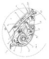
- the lid 3 is shown in Figure 1 in an open position and in Figure 2 in an intermediate position.
- the storage compartment 2 is shown closed, the cover 3 is omitted for clarity, so that a lid support 20 is visible on which the lid 3 is attached to itself.
- the opening and closing movement of the lid 3 is a substantially translational movement on an imaginary, approximately circular arc-shaped path, wherein the lid 3 is arranged approximately tangentially to the direction of movement.
- the lid 3 has on both sides in each case a lever 4, which protrudes rigidly and in one piece from an underside of the lid 3.
- the lever 4 passes through a gap 5 on the side of the opening of the storage compartment 2.
- the gap 5 extends above a depth (Length) of the opening of the storage compartment 2.
- the lever 4 is bent transversely to the direction of movement of the lid 3, that is bent twice in opposite directions approximately at right angles. As a result, the lever 4 is in a plane with the gap 5 and is offset in a region near the lid inwards into the opening of the storage compartment 2.
- the one-piece with the lid 3 lever 4 is part of a lever mechanism for guiding the lid 3 during opening and closing.
- the lever mechanism is designed as a flat four-bar linkage, which is arranged on an outer side of a side wall 6 and in a plane with the gap 5.
- the lever mechanism has two with respect to the storage compartment 2 fixed joints 7, 8 and two other joints 9, 10, which connect the cranked lever 4 articulated with two pivoting levers 11, 12.
- the joints 7, 8, 9 10 are arranged on the corners of an imaginary trapezoid, the two levers 11, 12 are thus not exactly parallel to each other, but diverge in the direction of the integral with the lid 3 lever 4.
- the integral with the lid 3 lever 4 extends over the joints 9, 10, which connect it to the levers 11, 12, arcuately up through the gap 5 to the lid 3.
- the trained as a four-bar lever mechanism 4, 11, 12 guides the lid 3 during opening and closing on the arcuate path described above.
- the cover 3 has on each side a lever mechanism 4, 11, 12, the two lever mechanism 4, 11, 12 are arranged congruently on the outer sides of the two side walls 6 of the storage compartment 2.
- One of the two levers 11 has a rack 13 which extends in a circular arc about an imaginary pivot axis of the lever 11 with the rack 13 meshes with a gear 14 which is non-rotatably mounted on a shaft which passes transversely through both side walls 6 of the storage compartment 2.
- the gears 14 synchronize the lever mechanism 4, 11, 12 on both sides of the storage compartment. 2
- the column 5 on both sides of the storage compartment 2 are covered with an open and closed lid 3 with a gap cover 15.
- the gap cover 15 is a strip-shaped aperture. It is pivotally connected in its central region with a coupling lever 16, the gap cover 15 is hinged to the far end pivotally connected to one of the two levers 12 of the lever mechanism 4, 11, 12. Due to the pivotal movement of the lever 12 during opening and closing of the lid 3, the gap cover 15 is lifted by the coupling lever 16 during the opening movement and during the closing movement of the lid 3 and lifted from the gap 5.
- the coupling lever 16 articulated on the lever mechanism 4, 11, 12 lowers the gap cover 15 back onto the gap 5, so that the gap 5 is covered by the gap cover 15 when the lid 3 is open and closed.
- the raised gap cover 15 and the thus released gap 5 are visible in the intermediate position of the lid 3 shown in Figure 2. Even in the raised position, the gap cover 15 is below the lid 3, ie between the lid 3 and the opening of the storage compartment 2.
- the lifting of the gap cover 15 during the opening movement and during the closing movement of the lid 3 avoids that the lever 4, the is integral with the lid 3 and further during the opening movement and during the closing movement of the lid 3 from the gap 5 as in open and closed lid, collided with the gap cover 15.
- the gap cover 15 is guided displaceably with a linear guide.
- the linear guide has a straight, keyhole-shaped slot 17 in the side wall 6 of the storage compartment 2, which extends approximately at right angles to the opening of the storage compartment 2.
- the slot 17 is penetrated by a pin 18 which is integral with a lever 19 which projects rigidly from an underside of the gap cover 15.
- the pin 18 is hidden in the drawing of his head.
- a circular extension of the keyhole-shaped slot 17 is used to push through the head of the pin 18 during assembly of the gap cover 15.
Landscapes
- Engineering & Computer Science (AREA)
- Mechanical Engineering (AREA)
- Transportation (AREA)
- Vehicle Step Arrangements And Article Storage (AREA)
Abstract
Description
Die Erfindung betrifft eine Vorrichtung mit einem Deckel mit den Merkmalen des Oberbegriffs des Anspruchs 1. Die Erfindung ist insbesondere für Ablagefächer, Aschenbecher oder Einbauräume in Kraftfahrzeugen vorgesehen.The invention relates to a device with a lid having the features of the preamble of claim 1. The invention is particularly intended for storage compartments, ashtrays or installation spaces in motor vehicles.
Eine derartige Vorrichtung ist bekannt aus der
Der Erfindung liegt die Aufgabe zugrunde, eine alternative Spaltabdeckung vorzuschlagen.The invention has for its object to provide an alternative gap coverage.
Diese Aufgabe wird erfindungsgemäß durch die Merkmale des Anspruchs 1 gelöst. Die Spaltabdeckung der erfindungsgemäßen Vorrichtung gibt während einer Öffnungsbewegung und während einer Schließbewegung des Deckels den Spalt, der von dem den Deckel führenden Hebel durchgriffen wird, frei und deckt den Spalt am Ende der Deckelbewegung, also sowohl bei offenem als auch bei geschlossenem Deckel, ab. Die Erfindung hat den Vorteil, dass der Spalt auch bei geschlossenem Deckel von der Spaltabdeckung abgedeckt ist. Der Spalt muss deswegen nicht vom geschlossenen Deckel abgedeckt sein. Weiterer Vorteil der Erfindung ist die Unterbringung der Spaltabdeckung bei geschlossenem Deckel dort, wo sich die Spaltabdeckung auch bei geöffnetem Deckel befindet. Es ist deswegen kein zusätzlicher Bauraum für die Spaltabdeckung beim geschlossenen Deckel notwendig. Die Spaltabdeckung vollführt beim Öffnen und beim Schließen des Deckels eine vergleichsweise kleine Bewegung, so dass auch hierfür nur ein vergleichsweise kleiner Bewegungsraum zur Verfügung stehen muss. Das ist ein nicht zu unterschätzender Vorteil bei den üblicherweise sehr engen Raumverhältnissen für Führungen und Getriebe des Deckels, die unterhalb bzw. hinter dem Spalt auf kleinem Bauraum untergebracht werden müssen. Zudem ermöglicht die Erfindung eine Bewegung der Spaltabdeckung nach oben bzw. außen, so dass sie nicht in den Bauraum für die Führung und das Getriebe des Deckels unterhalb bzw. hinter dem abzudeckenden Spalt eindringt.This object is achieved by the features of claim 1. The gap cover of the device according to the invention is during an opening movement and during a closing movement of the lid, the gap, which is penetrated by the lever leading the lid, free and covers the gap at the end of the lid movement, ie both open and closed Cover, off. The invention has the advantage that the gap is covered even when the lid is closed by the gap cover. The gap must therefore not be covered by the closed lid. Another advantage of the invention is the placement of the gap cover with the lid closed where the gap cover is also with the lid open. It is therefore no additional space for the gap cover the closed lid necessary. The gap cover performs a relatively small movement when opening and when closing the lid, so that even for this only a comparatively small space for movement must be available. This is a not to be underestimated advantage in the usually very tight space conditions for guides and gears of the lid, which must be accommodated below or behind the gap in a small space. In addition, the invention allows a movement of the gap cover upwards or outwards, so that they do not penetrate into the space for the guide and the transmission of the lid below or behind the gap to be covered.
Die Öffnungs- und die Schließbewegung des Deckels der erfindungsgemäßen Vorrichtung kann eine reine Schwenkbewegung, d.h. ausschließlich rotatorisch, sie kann eine reine Verschiebung, d.h. ausschließlich translatorisch, oder eine kombinierte rotatorisch/translatorische Bewegung sein.The opening and closing movement of the lid of the device according to the invention can be purely pivotal, i. exclusively rotational, it can be a pure displacement, i. exclusively translational, or a combined rotational / translational movement.
Eine Ausgestaltung der Erfindung sieht vor, dass die Spaltabdeckung beim Öffnen und beim Schließen des Deckels angehoben und am Ende der Öffnungs- und der Schließbewegung des Deckels wieder abgesenkt wird.An embodiment of the invention provides that the gap cover is raised during opening and closing of the lid and lowered again at the end of the opening and closing movement of the lid.
Bei einer Ausgestaltung der Erfindung ist der Hebel, der den Deckel führt, quer zu einer Bewegungsrichtung des Deckels gekröpft. Dadurch ist es möglich, dass sich der Hebel bereichsweise neben der Spaltabdeckung befindet, und zwar insbesondere bei offenem und bei geschlossenem Deckel, wenn die Spaltabdeckung den vom Hebel durchgriffenen Spalt abdeckt. Damit der Hebel bei der Bewegung des Deckels nicht mit der Spaltabdeckung kollidiert, wird die Spaltabdeckung beim Öffnen und beim Schließen des Deckels entsprechend bewegt, insbesondere angehoben und abgesenkt oder auch zur Seite bewegt.In one embodiment of the invention, the lever which guides the lid, is bent transversely to a direction of movement of the lid. This makes it possible that the lever is partially adjacent to the gap cover, in particular when the lid is open and closed, when the gap cover covers the gap penetrated by the lever. Thus, the lever does not collide with the movement of the lid with the gap cover, the gap cover when opening and closing the lid is moved accordingly, in particular raised and lowered or even moved to the side.
Eine Ausgestaltung der Erfindung sieht ein ebenes Hebelgetriebe zur Führung des Deckels vor. Ein Hebelgetriebe ermöglicht eine gewünschte, kombinierte translatorische und rotatorische Bewegung des Deckels.An embodiment of the invention provides a planar lever mechanism for guiding the lid. A lever mechanism allows a desired, combined translational and rotational movement of the lid.
Dabei sieht eine Weiterbildung ein Viergelenk als Hebelgetriebe vor, d. h. ein Getriebe mit vier Gelenken, von denen vorzugsweise zwei ortsfest sind.Here, a development provides a four-bar linkage as a lever gear, d. H. a transmission with four joints, two of which are preferably stationary.
Zum Antrieb der Spaltabdeckung sieht eine Ausgestaltung der Erfindung einen Koppelhebel vor, der die Spaltabdeckung mit dem Deckel verbindet. Die Verbindung kann auch mittelbar über das Hebelgetriebe erfolgen. Auf diese Weise ist ein einfacher, von der Deckelbewegung abgeleiteter Antrieb der Spaltabdeckung möglich.To drive the gap cover, an embodiment of the invention provides a coupling lever which connects the gap cover with the lid. The connection can also be made indirectly via the lever mechanism. In this way, a simple, derived from the cover movement drive the gap cover is possible.
Zur zusätzlichen Führung der Spaltabdeckung sieht eine Weiterbildung der Erfindung ein Linearlager vor, das die Spaltabdeckung mit Abstand vom Angriffspunkt des Koppelhebels verschieblich führt. Das Linearlager kann, muss aber keine Geradführung sein.For additional guidance of the gap cover, a further development of the invention provides a linear bearing which guides the gap cover at a distance from the point of application of the coupling lever. The linear bearing can, but does not have to be, a straight-line guide.
Die Erfindung wird nachfolgend anhand eines in der Zeichnung dargestellten Ausführungsbeispiels näher erläutert. Die drei Figuren zeigen eine Seite einer erfindungsgemäßer Vorrichtung in perspektivischer Darstellung in drei Deckelstellungen.The invention will be explained in more detail with reference to an embodiment shown in the drawing. The three figures show a side of an inventive device in a perspective view in three lid positions.
Die in der Zeichnung dargestellte, erfindungsgemäße Vorrichtung 1 weist ein Ablagefach 2 mit einer rechteckigen Öffnung auf. Grundsätzlich könnte es sich auch beispielsweise um einen Aschenbecher handeln. Die Öffnung ist mit einem Deckel 3 verschließ- bzw. abdeckbar. Der Deckel 3 ist in Figur 1 in einer offenen Stellung und in Figur 2 in einer Zwischenstellung dargestellt. In Figur 3 ist das Ablagefach 2 geschlossen dargestellt, wobei der Deckel 3 der Übersichtlichkeit wegen weggelassen ist, so dass ein Deckelträger 20 sichtbar ist, auf dem der Deckel 3 an sich angebracht ist. Die Öffnungs- und Schließbewegung des Deckels 3 ist eine im Wesentlichen translatorische Bewegung auf einer gedachten, näherungsweise kreisbogenförmigen Bahn, wobei der Deckel 3 näherungsweise tangential zur Bewegungsrichtung angeordnet ist.The illustrated in the drawing, inventive device 1 has a
Der Deckel 3 weist auf beiden Seiten jeweils einen Hebel 4 auf, der starr und einstückig von einer Unterseite des Deckels 3 absteht. Der Hebel 4 durchgreift einen Spalt 5 auf der Seite der Öffnung des Ablagefachs 2. Der Spalt 5 erstreckt sich Ober eine Tiefe (Länge) der Öffnung des Ablagefachs 2. Der Hebel 4 ist quer zur Bewegungsrichtung des Deckels 3 gekröpft, d. h. zweimal in entgegengesetzte Richtungen in etwa rechtwinklig abgewinkelt. Dadurch befindet sich der Hebel 4 in einer Ebene mit dem Spalt 5 und ist in einem deckelnahen Bereich nach innen in die Öffnung des Ablagefachs 2 versetzt.The
Der mit dem Deckel 3 einstückige Hebel 4 ist Teil eines Hebelgetriebes zur Führung des Deckels 3 beim Öffnen und Schließen. Das Hebelgetriebe ist als ebenes Viergelenk ausgebildet, das auf einer Außenseite einer Seitenwand 6 und in einer Ebene mit dem Spalt 5 angeordnet ist. Das Hebelgetriebe weist zwei bzgl. des Ablagefachs 2 ortsfeste Gelenke 7, 8 sowie zwei weitere Gelenke 9, 10 auf, die den gekröpften Hebel 4 gelenkig mit zwei schwenkbaren Hebeln 11, 12 verbinden. Die Gelenke 7, 8, 9 10 sind auf den Ecken eines gedachten Trapez angeordnet, die beiden Hebel 11, 12 stehen also nicht exakt parallel zueinander, sondern divergieren in Richtung des mit dem Deckel 3 einstückigen Hebels 4. Der mit dem Deckel 3 einstückige Hebel 4 erstreckt sich über die Gelenke 9, 10, die ihn mit den Hebeln 11, 12 verbinden, bogenförmig nach oben durch den Spalt 5 hindurch zum Deckel 3. Das als Viergelenk ausgebildete Hebelgetriebe 4, 11, 12 führt den Deckel 3 beim Öffnen und Schließen auf der oben beschriebenen bogenförmigen Bahn. Der Deckel 3 weist auf jeder Seite ein Hebelgetriebe 4, 11, 12 auf, die beiden Hebelgetriebe 4, 11, 12 sind deckungsgleich auf den Außenseiten der beiden Seitenwände 6 des Ablagefachs 2 angeordnet. Einer der beiden Hebel 11 weist eine Zahnstange 13 auf, die kreisbogenförmig um eine gedachte Schwenkachse des Hebels 11 verläuft Mit der Zahnstange 13 kämmt ein Zahnrad 14, das drehfest auf einer Welle sitzt, die quer durch beide Seitenwände 6 des Ablagefachs 2 hindurchgeht. Die Zahnräder 14 synchronisieren die Hebelgetriebe 4, 11, 12 auf beiden Seiten des Ablagefachs 2.The one-piece with the
Die Spalte 5 auf beiden Seiten des Ablagefachs 2 sind bei offenem und bei geschlossenem Deckel 3 mit einer Spaltabdeckung 15 abgedeckt. Die Spaltabdeckung 15 ist eine streifenförmige Blende. Sie ist in ihrem Mittelbereich gelenkig mit einem Koppelhebel 16 verbunden, dessen der Spaltabdeckung 15 fernes Ende schwenkbar an einem der beiden Hebel 12 des Hebelgetriebes 4, 11, 12 angelenkt ist. Durch die Schwenkbewegung des Hebels 12 beim Öffnen und beim Schließen des Deckels 3 wird die Spaltabdeckung 15 vom Koppelhebel 16 während der Öffnungsbewegung und während der Schließbewegung des Deckels 3 angehoben und vom Spalt 5 abgehoben.The column 5 on both sides of the
Am Ende der Öffnungsbewegung und der Schließbewegung des Deckels 3 senkt der am Hebelgetriebe 4, 11, 12 angelenkte Koppelhebel 16 die Spaltabdeckung 15 wieder auf den Spalt 5 ab, so dass bei offenem und geschlossenem Deckel 3 der Spalt 5 von der Spaltabdeckung 15 abgedeckt ist. Die angehobene Spaltabdeckung 15 und der dadurch freigegebene Spalt 5 sind in der in Figur 2 dargestellten Zwischenstellung des Deckels 3 sichtbar. Auch in der angehobenen Stellung befindet sich die Spaltabdeckung 15 unterhalb des Deckels 3, also zwischen dem Deckel 3 und der Öffnung des Ablagefachs 2. Das Anheben der Spaltabdeckung 15 während der Öffnungsbewegung und während der Schließbewegung des Deckels 3 vermeidet, dass der Hebel 4, der mit dem Deckel 3 einstückig ist und der während der Öffnungsbewegung und während der Schließbewegung des Deckels 3 weiter aus dem Spalt 5 vortritt als bei offenem und bei geschlossenem Deckel, mit der Spaltabdeckung 15 kollidiert.At the end of the opening movement and the closing movement of the
An einem Ende ist die Spaltabdeckung 15 mit einer Linearführung verschieblich geführt. Die Linearführung weist einen geraden, schlüssellochförmigen Schlitz 17 in der Seitenwand 6 des Ablagefachs 2 auf, der in etwa rechtwinklig zur Öffnung des Ablagefachs 2 verläuft. Der Schlitz 17 wird von einem Zapfen 18 durchgriffen, der einstückig mit einem Hebel 19 ist, der starr von einer Unterseite der Spaltabdeckung 15 absteht. Der Zapfen 18 ist in der Zeichnung von seinem Kopf verdeckt. Eine kreisförmige Erweiterung des schlüssellochförmigen Schlitzes 17 dient zum Durchstecken des Kopfs des Zapfens 18 bei der Montage der Spaltabdeckung 15. Durch die Geometrie des Hebelgetriebes 4, 11, 12, des Koppelhebels 16 und der Linearführung 17, 18 wird die gewünschte Bewegung der Spaltabdeckung 15 beim Öffnen und beim Schließen des Deckels 3 erreicht.At one end, the
Claims (7)
Applications Claiming Priority (1)
| Application Number | Priority Date | Filing Date | Title |
|---|---|---|---|
| DE200510050797 DE102005050797A1 (en) | 2005-10-24 | 2005-10-24 | Device with a lid |
Publications (1)
| Publication Number | Publication Date |
|---|---|
| EP1777110A1 true EP1777110A1 (en) | 2007-04-25 |
Family
ID=37671140
Family Applications (1)
| Application Number | Title | Priority Date | Filing Date |
|---|---|---|---|
| EP06021748A Withdrawn EP1777110A1 (en) | 2005-10-24 | 2006-10-17 | Device with a cover |
Country Status (2)
| Country | Link |
|---|---|
| EP (1) | EP1777110A1 (en) |
| DE (1) | DE102005050797A1 (en) |
Families Citing this family (1)
| Publication number | Priority date | Publication date | Assignee | Title |
|---|---|---|---|---|
| DE102011053391B4 (en) * | 2011-09-08 | 2025-07-03 | Dr. Ing. H.C. F. Porsche Aktiengesellschaft | Storage compartment lid |
Citations (5)
| Publication number | Priority date | Publication date | Assignee | Title |
|---|---|---|---|---|
| DE20002290U1 (en) * | 2000-02-09 | 2000-04-13 | Jos. Weber GmbH & Co. KG Kunststofftechnik und Formenbau, 35683 Dillenburg | Ashtrays for vehicles or the like |
| EP1120314A2 (en) * | 2000-01-27 | 2001-08-01 | Volkswagen Aktiengesellschaft | Receptacle for a vehicle |
| DE10029088A1 (en) * | 2000-06-13 | 2002-01-10 | Jos Weber Gmbh & Co Kg Kunstst | Container for vehicles has rotatable gap sealing element operated by gravity force or spring force, or force-operated by hinged cover, and with guide, track or cam face bearing upon component connected to cover |
| DE20023500U1 (en) * | 2000-01-27 | 2004-07-08 | Volkswagen Ag | Accessory for vehicle dashboard, e.g. storage compartment, moneybox or ashtray; has casing with hinged cover that is at least partly inserted in intermediate space in casing in open position |
| DE10356385A1 (en) * | 2003-12-03 | 2005-06-30 | Fischer Automotive Systems Gmbh | Spring operating drive for cover of storage compartment in automobile has spring element used for displacement of sliding carriage coupled to cover via drive pin cooperating with drive slot of drive lever |
-
2005
- 2005-10-24 DE DE200510050797 patent/DE102005050797A1/en not_active Withdrawn
-
2006
- 2006-10-17 EP EP06021748A patent/EP1777110A1/en not_active Withdrawn
Patent Citations (5)
| Publication number | Priority date | Publication date | Assignee | Title |
|---|---|---|---|---|
| EP1120314A2 (en) * | 2000-01-27 | 2001-08-01 | Volkswagen Aktiengesellschaft | Receptacle for a vehicle |
| DE20023500U1 (en) * | 2000-01-27 | 2004-07-08 | Volkswagen Ag | Accessory for vehicle dashboard, e.g. storage compartment, moneybox or ashtray; has casing with hinged cover that is at least partly inserted in intermediate space in casing in open position |
| DE20002290U1 (en) * | 2000-02-09 | 2000-04-13 | Jos. Weber GmbH & Co. KG Kunststofftechnik und Formenbau, 35683 Dillenburg | Ashtrays for vehicles or the like |
| DE10029088A1 (en) * | 2000-06-13 | 2002-01-10 | Jos Weber Gmbh & Co Kg Kunstst | Container for vehicles has rotatable gap sealing element operated by gravity force or spring force, or force-operated by hinged cover, and with guide, track or cam face bearing upon component connected to cover |
| DE10356385A1 (en) * | 2003-12-03 | 2005-06-30 | Fischer Automotive Systems Gmbh | Spring operating drive for cover of storage compartment in automobile has spring element used for displacement of sliding carriage coupled to cover via drive pin cooperating with drive slot of drive lever |
Also Published As
| Publication number | Publication date |
|---|---|
| DE102005050797A1 (en) | 2007-04-26 |
Similar Documents
| Publication | Publication Date | Title |
|---|---|---|
| DE4443521C1 (en) | Coverable container for vehicle | |
| DE3345122C2 (en) | Vehicle sunroof | |
| AT501468B1 (en) | SWING SLIDING | |
| DE3137191C2 (en) | Wind deflector on a vehicle roof | |
| DD252530A5 (en) | HARVESTER | |
| EP2147178A1 (en) | Hinge arrangement | |
| DE69915122T2 (en) | CONSTRUCTION OF AN OPENING VEHICLE ROOF | |
| DE102009047422A1 (en) | Household appliance, in particular dishwasher | |
| EP0422678B1 (en) | Luggage carrier | |
| EP2380459B1 (en) | Ejector device | |
| DE69114201T2 (en) | Motor vehicle lifting sunroof. | |
| EP2089660B1 (en) | Extractor hood | |
| DE102009031686B4 (en) | Drawer front with locking mechanism for locking drawers in vehicles | |
| DE69903407T2 (en) | OPENABLE ROOF CONSTRUCTION FOR A VEHICLE | |
| DE102011085177A1 (en) | Drive system for roof system of motor car, has safety devices comprising stop surfaces displaced against each other during arrangement of carriage outside of safety position such that surfaces are bypassed together during movement of arm | |
| DE10039305A1 (en) | Mounting for lid of storage compartment in car comprises lever mounted on pivot on floor of compartment and connected by second pivot to lid, second lever mounted on third pivot on roof of compartment and connected to lid by fourth pivot | |
| EP3017686B1 (en) | CUTTING HEAD, ESPECIALLY FOR A SÉCATEUR | |
| EP1777110A1 (en) | Device with a cover | |
| DE3823316C2 (en) | ||
| EP1281567A2 (en) | Beverage holder | |
| WO2011124453A1 (en) | Device for adjusting the inclination of a front panel | |
| EP0551840B1 (en) | Sliding sunroof for motorvehicle | |
| DE3825192C2 (en) | ||
| EP0185246B1 (en) | Rear or front lid hinge of a passenger car | |
| EP1400402B1 (en) | Built-in ashtray for a motor vehicle |
Legal Events
| Date | Code | Title | Description |
|---|---|---|---|
| PUAI | Public reference made under article 153(3) epc to a published international application that has entered the european phase |
Free format text: ORIGINAL CODE: 0009012 |
|
| AK | Designated contracting states |
Kind code of ref document: A1 Designated state(s): AT BE BG CH CY CZ DE DK EE ES FI FR GB GR HU IE IS IT LI LT LU LV MC NL PL PT RO SE SI SK TR |
|
| AX | Request for extension of the european patent |
Extension state: AL BA HR MK YU |
|
| 17P | Request for examination filed |
Effective date: 20070725 |
|
| 17Q | First examination report despatched |
Effective date: 20070823 |
|
| AKX | Designation fees paid |
Designated state(s): AT BE BG CH CY CZ DE DK EE ES FI FR GB GR HU IE IS IT LI LT LU LV MC NL PL PT RO SE SI SK TR |
|
| GRAP | Despatch of communication of intention to grant a patent |
Free format text: ORIGINAL CODE: EPIDOSNIGR1 |
|
| STAA | Information on the status of an ep patent application or granted ep patent |
Free format text: STATUS: THE APPLICATION IS DEEMED TO BE WITHDRAWN |
|
| 18D | Application deemed to be withdrawn |
Effective date: 20090219 |