EP1777111B1 - Multifuntionelle Befestigungsvorrichtung für eine elektrische Gerät - Google Patents
Multifuntionelle Befestigungsvorrichtung für eine elektrische Gerät Download PDFInfo
- Publication number
- EP1777111B1 EP1777111B1 EP05109801A EP05109801A EP1777111B1 EP 1777111 B1 EP1777111 B1 EP 1777111B1 EP 05109801 A EP05109801 A EP 05109801A EP 05109801 A EP05109801 A EP 05109801A EP 1777111 B1 EP1777111 B1 EP 1777111B1
- Authority
- EP
- European Patent Office
- Prior art keywords
- mounting bracket
- electrical device
- mounting
- support
- connecting means
- Prior art date
- Legal status (The legal status is an assumption and is not a legal conclusion. Google has not performed a legal analysis and makes no representation as to the accuracy of the status listed.)
- Expired - Lifetime
Links
Images


Classifications
-
- F—MECHANICAL ENGINEERING; LIGHTING; HEATING; WEAPONS; BLASTING
- F16—ENGINEERING ELEMENTS AND UNITS; GENERAL MEASURES FOR PRODUCING AND MAINTAINING EFFECTIVE FUNCTIONING OF MACHINES OR INSTALLATIONS; THERMAL INSULATION IN GENERAL
- F16M—FRAMES, CASINGS OR BEDS OF ENGINES, MACHINES OR APPARATUS, NOT SPECIFIC TO ENGINES, MACHINES OR APPARATUS PROVIDED FOR ELSEWHERE; STANDS; SUPPORTS
- F16M13/00—Other supports for positioning apparatus or articles; Means for steadying hand-held apparatus or articles
- F16M13/02—Other supports for positioning apparatus or articles; Means for steadying hand-held apparatus or articles for supporting on, or attaching to, an object, e.g. tree, gate, window-frame, cycle
-
- B—PERFORMING OPERATIONS; TRANSPORTING
- B60—VEHICLES IN GENERAL
- B60R—VEHICLES, VEHICLE FITTINGS, OR VEHICLE PARTS, NOT OTHERWISE PROVIDED FOR
- B60R11/00—Arrangements for holding or mounting articles, not otherwise provided for
-
- B—PERFORMING OPERATIONS; TRANSPORTING
- B60—VEHICLES IN GENERAL
- B60R—VEHICLES, VEHICLE FITTINGS, OR VEHICLE PARTS, NOT OTHERWISE PROVIDED FOR
- B60R11/00—Arrangements for holding or mounting articles, not otherwise provided for
- B60R11/02—Arrangements for holding or mounting articles, not otherwise provided for for radio sets, television sets, telephones, or the like; Arrangement of controls thereof
- B60R11/0258—Arrangements for holding or mounting articles, not otherwise provided for for radio sets, television sets, telephones, or the like; Arrangement of controls thereof for navigation systems
-
- B—PERFORMING OPERATIONS; TRANSPORTING
- B60—VEHICLES IN GENERAL
- B60R—VEHICLES, VEHICLE FITTINGS, OR VEHICLE PARTS, NOT OTHERWISE PROVIDED FOR
- B60R11/00—Arrangements for holding or mounting articles, not otherwise provided for
- B60R2011/0042—Arrangements for holding or mounting articles, not otherwise provided for characterised by mounting means
- B60R2011/0049—Arrangements for holding or mounting articles, not otherwise provided for characterised by mounting means for non integrated articles
- B60R2011/0064—Connection with the article
- B60R2011/0071—Connection with the article using latches, clips, clamps, straps or the like
Definitions
- the invention relates to a multifunctional mounting bracket for an electrical device and more specifically to a multifunctional mounting bracket for a wireless access point device (WAP).
- WAP wireless access point device
- Document DE 196 32 287 A1 discloses a warning device and a method for mounting and demounting the device to a wall holder.
- a snap-hook of the holder which is engaged in a respective recess of the warning device must be disengaged and then a stop screw of the holder which works as a locking device must be unscrewed. Finally the warning device can be separated from the holder.
- Document US 2005/0077070A1 discloses an electrical device which can be attached to a holder in a vehicle.
- the holder is mounted to the inner side of the roof of the vehicle.
- the electrical device is fixed in the holder by means of a first and a second connection.
- the first connection is realised as a hook, wherein the electrical device can pivot in relation to the holder, and the second connection is realised as a locking device, wherein the electrical device can be locked.
- Document US 6,010,102 discloses a mounting system for restraining a device within a vehicle having a dashboard and a windshield.
- the present invention proposes a multifunctional mounting bracket for an electrical device, especially for a wireless access point device ("WAP”), with the features of claim 1.
- WAP wireless access point device
- the mounting bracket comprises means for mounting the electrical device to a first support and - as an alternative - to a second support.
- the mounting angle between the electrical device and the first support on the one hand side and the second support on the other hand side is different.
- the mounting angle is preferably defined as a pivoting angle between support and electrical device, whereby the electrical device is pivoted toward the support or away from the support.
- the mounting bracket comprises a first area of contact for contacting the first support and a second area of contact for contacting the second support, whereby the two areas of contact lie in different planes, especially in crossing and/or non-parallel planes.
- the mounting bracket embodies a single and easy to use solution for mounting the electrical device in various positions and/or mounting angles. Due to the multifunctional character of the mounting bracket it is not necessary anymore to sell an electrical device together with a plurality of holders in order to enable the user to mount the electrical device as he likes. By using the multifunctional mounting bracket instead of a plurality of holders no waste or lost of unused material occurs, which results in minor production costs and protection of the environment.
- the mounting bracket can be used for stationary, quasi-stationary an/or rental purposes of the electrical device, as the electrical device can easily be mounted or demounted, whereby all mounting material needed is realised as the mounting bracket.
- the first support installation allows a parallel or substantially parallel mounting of the electrical device to the first support and/or the second support installation allows a perpendicular or substantially perpendicular mounting of the electrical device to the alternative second support.
- the mounting device enables at least two different mounting alternatives for the electrical device, preferably so that the electrical device can be mounted on a wall or a ceiling and alternatively on a tripod.
- the areas of contact of the mounting bracket as defined above are perpendicular to each other. With this embodiment the most used mounting alternatives are covered by the mounting bracket.
- the means for mounting comprises first fastening means allowing a fastening of the mounting bracket to the first support, first connecting means for connecting the mounting bracket with the electrical device for the first support installation, second fastening means allowing the alternative fastening of the mounting bracket to the second support and second connecting means for connecting the mounting bracket with the electrical device for the second support installation.
- the mounting bracket comprises two pairs of mounting means whereby the first pair is adapted for the mounting of the electrical device on the first support and the second pair is adapted for mounting of the electrical device on the second support.
- the two pairs and/or the fastening and/or connecting means are arranged separately on the mounting bracket and are especially arranged mechanically isolated from each other.
- at least one of the mounting means has a double purpose preferably so that the functions of the first and second fastening means or the functions of the first and second connecting means are realised in a combined fastening means or combined connecting means respectively.
- the mounting means preferably all mounting means, especially the fastening and/or connecting means are realised as or comprise recesses in the mounting bracket.
- This embodiment allows a cost-effective production of the mounting bracket as the respective mounting means can be produced by a simple stamping or punching process.
- Preferably all mounting means of the mounting bracket are produced by a stamping process or by a combined stamping/forming process. Further it is advantageously in case the mounting bracket is realised as an one-piece part, especially as an one-piece bending part.
- the mounting bracket has a three-sectional or tripartite shape, whereby preferably the three sections are angled to each other, more preferably are angled to each other with or substantially with a 45° angle between the sections.
- the mounting bracket shows an U-shaped or a broadened U-shaped cross-section with the second section defming the lying leg of the U.
- the inner side of the (U-shaped) bracket will be called concave surface and the outer side will be called convex surface.
- the first fastening means are arranged at the free and/or open end sections of the second section of the bracket and comprise protruded plain areas protruding from the convex surface side whereby the plain areas function as areas of contact for example for a wall or ceiling installation of the bracket.
- the first fastening means further comprise recesses in the plain areas for accommodating fixing means like screws or similar.
- the first connecting means is realised as receptacles for mounting links like latches and/or snap-hooks of the electrical device arranged in the second section, whereby the receptacles are adapted for accommodating the mounting links by a sliding movement of the electrical device along a first sliding directory, which is preferably parallel to the convex surface side of the second section.
- the second fastening means is arranged in the first section, preferably in the middle of the first section, and is embodied as a round recess like a through or clearance hole.
- the convex or concave surface side of the first section works as an area of contact for example for a tripod installation of the bracket.
- the second connecting means is realised in the third section and is adapted for receiving the mounting links of the electrical device by a sliding of the electrical device along a second sliding direction, which is parallel to the surface of the third section and whereby the angle between the first and second sliding direction is larger than 0° and preferably about 90°.
- first and second connecting means comprise holes for accommodating pins or protrusions protruding from the mounting links of the electrical device for securing the electrical device to the mounting bracket.
- a combination of an electrical device preferably as described above with the mounting bracket is claimed, whereby the electrical device comprises third connecting means adapted to match with the first and second connecting means of the bracket.
- the third connecting means are realised as mounting links and/or snap-hooks.
- the electrical device comprises receptacles for mounting links or the like protruding from the mounting bracket.
- the mounting bracket is fully integrated in the electrical device for the first support installation, whereby only the protruded areas of the first connecting means project from the rear side of the electrical device.
- the second section of the mounting bracket is parallel or substantially parallel to the rear side of the electrical device.
- the second and first section projects from the rear side of the electrical device, whereby preferably the first section of the mounting bracket is arranged perpendicular or substantially perpendicular to the rear side of the electrical device.
- a first step of mounting the electrical device is to fasten the mounting bracket on a tripod or alternatively to a wall or ceiling or the like.
- the positioning and fixing of the electrical device to the mounting bracket is done by means of sliding the mounting bracket into the mounting links in the rear cover of the electrical device. After placing the electrical device it can only be removed from the mounting bracket by using some force.
- the new mounting bracket is a single, easy to use solution for mounting an electrical device like a WAP on various supports, whereby preferably the mounting bracket is adapted to be mounted to a first support like a wall or ceiling and to a second support like a tripod.
- a further advantage which can be achieved is that all connecting means for connecting the electrical device to the mounting bracket are provided by the bracket or the electrical device and no extra fixing material is needed which can be lost or remains unused.
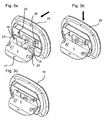
- Fig. 1 shows a mounting bracket 1 as an embodiment of the invention, which is realised as a one-piece bending part preferably made of a thin metal band or plate as semi-finished product.
- the mounting bracket 1 is coated for example by powder or lacquer.
- the mounting bracket 1 comprises two parallel bending edges 2 a and 2 b defming three sections I, II, III of the mounting bracket 1, whereby section II is a central section and sections I and III are arranged as side sections.
- the sections I, II and III are angled to each other by an angle of approximately 45° so that the section I an III have an angle of about 90° between. Due to the bent shape the mounting bracket 1 shows a concave surface 3 and a convex surface 4 which is turned away from the viewer in fig. 1 and thus not shown in fig. 1 .
- the central section II shows a rectangular or oblong shape, whereby the open or free edges 5 and 6 of the section II are slightly rounded.
- fastening means realised as protruded areas 7 and 8 with respective recesses 9 and 10 are provided.
- the protruded areas 7 and 8 are projecting from the convex surface side 4, defining plane contact areas 11 and 12 on the convex surface side 4.
- the protruded areas show a half-round shape which are open to the free edges 5 and 6.
- the recesses 9 and 10 are arranged in the middle of the protruded areas 7 and 8 and are realised as oblong holes both extending parallel to each other through the mounting bracket, whereby the oblong opening of recess 9 is orientated perpendicular to the bending edges 2 a and 2b and the oblong opening of recess 10 is arranged in parallel to the bending edges 2 a and 2b. In other words the oblong openings of the recesses 9 and 10 are orientated perpendicular to each other.
- the section II further comprises connecting means realised as cut-outs 13 and 14 with an identical trapezoidal shape as opening, whereby cut-outs 13 and 14 arranged on a common line parallel to bending edges 2 a and 2 b and whereby cut-out 13 is arranged near the protruded area 5 and cut-out 14 near protruded area 6.
- the parallel edges of the trapezoidal cut-outs 13 and 14 are arranged perpendicular to the bending edges 2 a and 2 b. Both cut-outs 13 and 14 are orientated towards a common direction, whereby the trapezoidal cut-outs 13 and 14 are positioned so that the respective shorter of the parallel edges of the cut-outs 13 and 14 head towards the common direction. Adjacent to the cut-outs 13 and 14 in the common direction and also on the common line through holes 15 and 16 are positioned.
- Section I viewed from the top, i.e. viewed on the concave surface side 3, shows a flat topped half-round shape.
- a clearance hole 17 is provided for accommodating a pin or a threaded bolt of a tripod.
- Section III comprises two receptacles realised as slots 18 and 19 which extend parallel to each other and perpendicular to the bending edges 2a and 2b.
- the distance between the slots 18 and 19 is the same as between the two shorter edges of the cut-outs 13 and 14.
- Adjacent to the slots 18 and 19 through-holes 20 and 21 are positioned in an analogous manner as the through-holes 15 and 16 in relation to the cut-outs 13 and 14.
- Section III is sub-divided into two sub-sections 22 and 23 by means of a central cut-out 24, so that the two-subsections 22 and 23 can be bent during connecting with the WAP ( fig. 3a, b, c ) independently from each other.
- FIGS 2a to 2c show a sequence during which the mounting bracket 1 is connected with a WAP (wireless access point device) 25.
- WAP wireless access point device
- the rear side of the WAP 25 shows a three-sectional or tripartite shape corresponding to the mounting bracket , whereby the first section 26 and the third section 27 are realised as a recess for the sections I and II respectively of the mounting bracket 1.
- the second section 28 comprises two snap-hooks 29 and 30 which are adapted to match with the cut-outs 13 and 14 of the mounting bracket.
- the mounting bracket is fastened to a wall or a ceiling, whereby fixing means, for example screws or the like, are guided through the recesses 9 and 10 and fixed into the wall or ceiling, so that the areas of contact 11 and 12 of the mounting device are in direct contact with the wall or ceiling.
- a second step the WAP 25 is attached to the mounting bracket, whereby the snap hooks 29 and 30 are guided through the cut-outs 13 and 14 with a movement perpendicular to the convex surface side 3 of section II of the mounting device.
- This step is shown by the figures 2a and 2b .
- a third step which is illustrated by figures 2b and 2c , the WAP 25 is slid in the above-introduced common direction, so that the snap-hooks 29 and 30 snap over the shorter edges of the cut-outs 13 and 14 thereby securing the WAP 25 to the mounting bracket 1 and thus mounting the WAP 25 to a wall or ceiling or - general speaking - to a plane support surface.
- a pin or a protrusion is arranged on the inner side of each snap-hook 29 or 30, which snaps in the through hole 15 or 16 respectively.
- the mounting bracket 1 is fully integrated in the body of the WAP 25.
- Figures 3 a to c are a sequence to illustrate the way of connecting mounting bracket 1 and WAP 25 for a tripod installation of the WAP 25.
- the mounting bracket 1 is fastened to a (not-shown) tripod by guiding and fixing a fixing means like a pin or threaded bolt of the tripod through the clearance hole 17.
- a fixing means like a pin or threaded bolt of the tripod through the clearance hole 17.
- the rear side of the WAP 25 is brought in contact with the convex surface side 4 of section III so that rear side and convex surface side 4 of section III are arranged in parallel.
- the WAP is slid in a sliding direction parallel to the extension of the slits 18 and 19 of the mounting bracket 1, whereby the snap-hooks 29 and 30 are slid into the slits 18 and 19 so that the mounting links of the snap-hooks 29 and 30 snap over the subsections 22 and 23 respectively.
- the mounting bracket 1 is a one-piece part which can be used as a holder for the WAP 25 without needing further mounting material.
- WAP 25 and mounting bracket 1 can be combined in two different ways: For wall or ceiling installation the WAP 25 is in contact with the concave surface 3 of the mounting bracket 1 and the wall or ceiling is in contact with areas of contact 11 and 12 on the convex surface side 4 of the mounting bracket 1.
- For tripod installation the rear side of the WAP 25 I is in contact with the convex surface side 4 of the mounting bracket 1 and areas of contact for contacting the tripod is provided in section I on both sides of the mounting bracket 1.
Landscapes
- Engineering & Computer Science (AREA)
- Mechanical Engineering (AREA)
- General Engineering & Computer Science (AREA)
- Radar, Positioning & Navigation (AREA)
- Remote Sensing (AREA)
- Casings For Electric Apparatus (AREA)
- Coupling Device And Connection With Printed Circuit (AREA)
- Mounting Components In General For Electric Apparatus (AREA)
- Connections Arranged To Contact A Plurality Of Conductors (AREA)
- Portable Nailing Machines And Staplers (AREA)
- Clamps And Clips (AREA)
- Details Of Connecting Devices For Male And Female Coupling (AREA)
Claims (10)
- Multifunktionelle Befestigungsvorrichtung (1) für ein elektrisches Gerät (25) mit Mitteln (7, 8, 9, 10, 13, 14, 17, 18, 19) zum Montieren des elektrischen Geräts (25) an einer ersten Stütze, wobei ein erster Montagewinkel zwischen dem elektrischen Gerät (25) und der ersten Stütze definiert ist, und zum Montieren des elektrischen Geräts (25) an einer alternativen zweiten Stütze, wobei ein zweiter Montagewinkel zwischen dem elektrischen Gerät und der zweiten Stütze definiert ist, wobei sich der zweite Montagewinkel vom ersten Montagewinkel unterscheidet,
dadurch gekennzeichnet, dass
das Montagemittel erste Befestigungsmittel (7, 8, 9, 10), die eine Befestigung der Befestigungsvorrichtung (1) an der ersten Stütze gestatten, erste Verbindungsmittel (13, 14) zum Verbinden der Befestigungsvorrichtung (1) mit dem elektrischen Gerät (25) für die erste Stützinstallierung, zweite Befestigungsmittel (17), die die alternative Befestigung der Befestigungsvorrichtung (1) an der zweiten Stütze gestatten und zweite Verbindungsmittel (18, 19) zum Verbinden der Befestigungsvorrichtung (1) mit dem elektrischen Gerät (25) für die zweite Stützinstallierung umfasst. - Befestigungsvorrichtung (1) nach Anspruch 1, dadurch gekennzeichnet, dass die erste Stützinstallierung eine parallele oder im Wesentlichen parallele Montage des elektrischen Geräts (25) an der ersten Stütze gestattet und/oder die zweite Stützinstallierung eine senkrechte oder im Wesentlichen senkrechte Montage des elektrischen Geräts (25) an der alternativen zweiten Stütze gestattet.
- Befestigungsvorrichtung (1) nach Anspruch 1, wobei erste und zweite Befestigungsmittel (7, 8, 9, 10, 17) und erste und zweite Verbindungsmittel (13, 14, 18, 19) getrennt voneinander an der Befestigungsvorrichtung (1) angeordnet sind.
- Befestigungsvorrichtung (1) nach Anspruch 1 oder 3, wobei mindestens ein und/oder alle Befestigungsmittel (7, 8, 9, 10, 17) und/oder Verbindungsmittel (13, 14, 18, 19) als Ausnehmungen in der Befestigungsvorrichtung (1) ausgeführt sind und/oder Ausnehmungen in der Befestigungsvorrichtung (1) umfassen und/oder die Befestigungsvorrichtung ein einteiliges Teil ist.
- Befestigungsvorrichtung (1) nach einem der Ansprüche 2 bis 4, dadurch gekennzeichnet, dass die Befestigungsvorrichtung (1) in einer Form mit drei Abschnitten ausgeführt ist, wobei ein erster Abschnitt (I) das zweite Befestigungsmittel (17) umfasst und/oder ein zweiter Abschnitt (II) das erste Befestigungsmittel und das erste Verbindungsmittel und/oder ein dritter Abschnitt das zweite Verbindungsmittel.
- Befestigungsvorrichtung (1) nach Anspruch 5, wobei die drei Abschnitte (I, II, III) mit einem U-förmigen oder einem verbreiterten U-förmigen Querschnitt angeordnet sind, wobei der liegende Schenkel durch den zweiten Abschnitt definiert ist.
- Befestigungsvorrichtung (1) nach einem der Ansprüche 2 bis 6, wobei
das erste Befestigungsmittel als mindestens ein vorragender Bereich (7, 8) ausgeführt ist, der einen Kontaktbereich (11, 12) für eine Wand oder eine Decke o. Ä. definiert, mit einer Ausnehmung (9, 10) zur Unterbringung eines Fixierungsmittels
und/oder
das zweite Befestigungsmittel als ein Loch (17) zur Unterbringung eines Stifts oder eines Gewindebolzens eines Stativs o. Ä. ausgeführt ist
und/oder
das erste Verbindungsmittel als mindestens eine erste Aufnahme (13, 14) zur Unterbringung einer Montagelasche (29, 30) des elektrischen Geräts (25) ausgeführt ist, wobei die Montagelasche (29, 30) durch eine Gleitbewegung entlang einer ersten Gleitrichtung fixiert wird,
und/oder
das zweite Verbindungsmittel als mindestens eine zweite Aufnahme (18, 19) zur Unterbringung der Montagelasche (29, 30) des elektrischen Geräts (25) ausgeführt ist, wobei die Montagelasche (29, 30) durch eine Gleitbewegung entlang einer zweiten Gleitrichtung fixiert wird, die sich von der ersten Gleitrichtung unterscheidet und/oder senkrecht zur ersten Gleitrichtung verläuft. - Befestigungsvorrichtung (1) nach einem der vorhergehenden Ansprüche, wobei das erste und das zweite Verbindungsmittel Löcher (15, 16, 20, 21) zur Unterbringung von Stiften umfassen, die von den Montagelaschen (29, 30) des elektrischen Geräts (25) vorragen, um das elektrische Gerät (25) an der Befestigungsvorrichtung (1) zu befestigen.
- Kombination aus einem elektrischen Gerät (25) mit einer Befestigungsvorrichtung (1) nach einem der vorhergehenden Ansprüche, wobei das elektrische Gerät (25) dritte Verbindungsmittel (29, 30) umfasst, die geeignet sind, mit dem ersten und dem zweiten Verbindungsmittel der Befestigungsvorrichtung (1) zusammenzupassen.
- Kombination nach Anspruch 9, wobei die Befestigungsvorrichtung (1) für die erste Stützinstallierung in das elektrische Gerät (25) integriert ist und/oder für die zweite Stützinstallierung aus dem elektrischen Gerät (25) vorragt.
Priority Applications (6)
| Application Number | Priority Date | Filing Date | Title |
|---|---|---|---|
| AT05109801T ATE430065T1 (de) | 2005-10-20 | 2005-10-20 | Multifuntionelle befestigungsvorrichtung für eine elektrische gerät |
| DE602005014240T DE602005014240D1 (de) | 2005-10-20 | 2005-10-20 | Multifuntionelle Befestigungsvorrichtung für eine elektrische Gerät |
| EP05109801A EP1777111B1 (de) | 2005-10-20 | 2005-10-20 | Multifuntionelle Befestigungsvorrichtung für eine elektrische Gerät |
| CN2006101362679A CN1953103B (zh) | 2005-10-20 | 2006-10-18 | 用于电子设备的多功能安装支架 |
| US11/583,879 US7793901B2 (en) | 2005-10-20 | 2006-10-19 | Multifunctional mounting bracket for an electrical device |
| JP2006286778A JP2007180500A (ja) | 2005-10-20 | 2006-10-20 | 電気デバイスのための多機能取付けブラケット |
Applications Claiming Priority (1)
| Application Number | Priority Date | Filing Date | Title |
|---|---|---|---|
| EP05109801A EP1777111B1 (de) | 2005-10-20 | 2005-10-20 | Multifuntionelle Befestigungsvorrichtung für eine elektrische Gerät |
Publications (2)
| Publication Number | Publication Date |
|---|---|
| EP1777111A1 EP1777111A1 (de) | 2007-04-25 |
| EP1777111B1 true EP1777111B1 (de) | 2009-04-29 |
Family
ID=35478889
Family Applications (1)
| Application Number | Title | Priority Date | Filing Date |
|---|---|---|---|
| EP05109801A Expired - Lifetime EP1777111B1 (de) | 2005-10-20 | 2005-10-20 | Multifuntionelle Befestigungsvorrichtung für eine elektrische Gerät |
Country Status (6)
| Country | Link |
|---|---|
| US (1) | US7793901B2 (de) |
| EP (1) | EP1777111B1 (de) |
| JP (1) | JP2007180500A (de) |
| CN (1) | CN1953103B (de) |
| AT (1) | ATE430065T1 (de) |
| DE (1) | DE602005014240D1 (de) |
Cited By (1)
| Publication number | Priority date | Publication date | Assignee | Title |
|---|---|---|---|---|
| JP2006030187A (ja) * | 2004-07-21 | 2006-02-02 | Dr Johannes Heidenhain Gmbh | 位置測定装置の取付け補助装置並びにこの取付け補助装置を有するスケール及び位置測定装置 |
Families Citing this family (11)
| Publication number | Priority date | Publication date | Assignee | Title |
|---|---|---|---|---|
| US8668179B2 (en) * | 2008-04-08 | 2014-03-11 | Garmin Switzerland Gmbh | Mount for an electronic device |
| USD613578S1 (en) * | 2008-08-14 | 2010-04-13 | D & D Group Pty Ltd | Mounting bracket |
| CN102705654A (zh) * | 2012-06-14 | 2012-10-03 | 昆山维金五金制品有限公司 | 一种片状冲压件 |
| JP6003519B2 (ja) * | 2012-10-19 | 2016-10-05 | オムロン株式会社 | 機器が取り付けられる取付板、機器、およびシステム |
| US20160044911A1 (en) * | 2014-08-12 | 2016-02-18 | Ancestry Outdoors, LLC | Bracket and Hanger System to Aid in Hanging a Tree Stand |
| CN107709159B (zh) * | 2015-04-13 | 2021-03-02 | 新科宇航 | 便携式电子设备支架 |
| USD858262S1 (en) * | 2016-05-31 | 2019-09-03 | Erico International Corporation | Mounting bracket for a brace |
| US11158927B1 (en) | 2020-07-21 | 2021-10-26 | Juniper Networks, Inc. | Wireless access point vertical mount |
| USD1016714S1 (en) * | 2022-06-23 | 2024-03-05 | Shenzhen Zhengtu Auto Accessories Co., Ltd. | Vehicle mounting bracket |
| US20240392916A1 (en) * | 2023-05-24 | 2024-11-28 | Tyco Fire & Security Gmbh | Mounting bracket for thermostat |
| DE102023207436A1 (de) * | 2023-08-03 | 2025-02-06 | Stellantis Auto Sas | Haltevorrichtung für ein Kraftfahrzeug |
Family Cites Families (13)
| Publication number | Priority date | Publication date | Assignee | Title |
|---|---|---|---|---|
| US1764071A (en) * | 1929-01-30 | 1930-06-17 | Thomas E Grinslade | Radio aerial bracket |
| US4113217A (en) * | 1977-04-07 | 1978-09-12 | Scientific Dimensions, Inc. | Apparatus for removably mounting equipment to a vehicle |
| US4441684A (en) * | 1981-11-25 | 1984-04-10 | The Coca-Cola Company | Pump mounting bracket |
| USD296075S (en) * | 1986-05-15 | 1988-06-07 | Jones Robert E | Adjustable height mount for pump motor |
| US4930696A (en) * | 1989-07-31 | 1990-06-05 | Chrysler Corporation | Mounting means for vehicle audio device |
| US5222374A (en) * | 1990-05-11 | 1993-06-29 | Whirlpool Corporation | Assembly method and construction for a room air conditioner |
| US5188328A (en) * | 1992-01-13 | 1993-02-23 | Thompson Thomas O | Undercounter revolver support |
| DE19632287B4 (de) | 1996-08-09 | 2007-02-22 | Robert Bosch Gmbh | Externsignalgeber und Verfahren zur Auslösung eines Voralarms bei einem Externsignalgeber |
| JP3431790B2 (ja) * | 1997-02-17 | 2003-07-28 | 松下電器産業株式会社 | 分離型空気調和装置の室外機据付け具 |
| US6010102A (en) * | 1997-07-24 | 2000-01-04 | Highwaymaster Communications, Inc. | Multiplane bracket |
| DE10202034A1 (de) | 2002-01-18 | 2003-07-24 | Bosch Gmbh Robert | Elektrisches Gerät zum Anbringen an einer Halterung und Halterung hierfür |
| WO2004083658A1 (en) * | 2003-03-17 | 2004-09-30 | Koninklijke Philips Electronics N.V. | Flat panel display unit provided with attachment means and attachment unit for the removable attachment of an object |
| US7455278B2 (en) * | 2007-02-13 | 2008-11-25 | Huang-Hsi Hsu | Motor frame |
-
2005
- 2005-10-20 DE DE602005014240T patent/DE602005014240D1/de not_active Expired - Lifetime
- 2005-10-20 EP EP05109801A patent/EP1777111B1/de not_active Expired - Lifetime
- 2005-10-20 AT AT05109801T patent/ATE430065T1/de not_active IP Right Cessation
-
2006
- 2006-10-18 CN CN2006101362679A patent/CN1953103B/zh active Active
- 2006-10-19 US US11/583,879 patent/US7793901B2/en active Active
- 2006-10-20 JP JP2006286778A patent/JP2007180500A/ja not_active Withdrawn
Cited By (1)
| Publication number | Priority date | Publication date | Assignee | Title |
|---|---|---|---|---|
| JP2006030187A (ja) * | 2004-07-21 | 2006-02-02 | Dr Johannes Heidenhain Gmbh | 位置測定装置の取付け補助装置並びにこの取付け補助装置を有するスケール及び位置測定装置 |
Also Published As
| Publication number | Publication date |
|---|---|
| US20080048076A1 (en) | 2008-02-28 |
| EP1777111A1 (de) | 2007-04-25 |
| JP2007180500A (ja) | 2007-07-12 |
| ATE430065T1 (de) | 2009-05-15 |
| CN1953103B (zh) | 2011-03-30 |
| DE602005014240D1 (de) | 2009-06-10 |
| CN1953103A (zh) | 2007-04-25 |
| US7793901B2 (en) | 2010-09-14 |
Similar Documents
| Publication | Publication Date | Title |
|---|---|---|
| EP1777111B1 (de) | Multifuntionelle Befestigungsvorrichtung für eine elektrische Gerät | |
| CA2195823C (en) | Lampholder mounting system | |
| US7052035B2 (en) | Assembly unit having an airbag module and a vehicle steering wheel | |
| US4772079A (en) | Cover assembly for removably mounted electronic equipment | |
| US5215332A (en) | Quick release seat belt anchor | |
| NL2008358C2 (en) | Safety hammer, holder for a safety hammer, system of a safety hammer and holder, method for assembly of a safety hammer. | |
| EP1957323B1 (de) | Verschluss | |
| JP5839739B2 (ja) | クリップおよびそのクリップを備える部材取付構造 | |
| US7753458B2 (en) | Expansion card mounting apparatus | |
| JP2004323010A (ja) | ドライバ側エアバッグをステアリングホイールに連結する方法と装置 | |
| WO2002066292A3 (en) | Running board mounting bracket | |
| JP2005506732A (ja) | 自動車用アンテナ実装組立体 | |
| US8481190B2 (en) | Method, apparatus, and system for mounting an electronic device | |
| KR20010079749A (ko) | 스냅-삽입 커넥터 시스템 | |
| EP3599386B1 (de) | Bolzenverriegelungswerkzeug | |
| US20070216180A1 (en) | Front cowl trim for headlights | |
| EP0967092A3 (de) | Radzierblende | |
| WO2020052680A1 (en) | Antenna module for motor vehicle | |
| US5465200A (en) | Lamp assembly fastening system | |
| US7967360B2 (en) | Removable visor | |
| EP1931043A2 (de) | Befestigungs- und Abnahmemechanismus für eine tragbare elektronische Vorrichtung | |
| US4103982A (en) | Accessory locking mount | |
| EP1422109B1 (de) | D-Ring Halterung | |
| US4364051A (en) | Mobile antenna mounting assembly with resilient locking means | |
| CN212182995U (zh) | 一种可安装多种线缆的卡具 |
Legal Events
| Date | Code | Title | Description |
|---|---|---|---|
| PUAI | Public reference made under article 153(3) epc to a published international application that has entered the european phase |
Free format text: ORIGINAL CODE: 0009012 |
|
| AK | Designated contracting states |
Kind code of ref document: A1 Designated state(s): AT BE BG CH CY CZ DE DK EE ES FI FR GB GR HU IE IS IT LI LT LU LV MC NL PL PT RO SE SI SK TR |
|
| AX | Request for extension of the european patent |
Extension state: AL BA HR MK YU |
|
| 17P | Request for examination filed |
Effective date: 20071025 |
|
| AKX | Designation fees paid |
Designated state(s): AT BE BG CH CY CZ DE DK EE ES FI FR GB GR HU IE IS IT LI LT LU LV MC NL PL PT RO SE SI SK TR |
|
| 17Q | First examination report despatched |
Effective date: 20071218 |
|
| GRAP | Despatch of communication of intention to grant a patent |
Free format text: ORIGINAL CODE: EPIDOSNIGR1 |
|
| GRAS | Grant fee paid |
Free format text: ORIGINAL CODE: EPIDOSNIGR3 |
|
| GRAA | (expected) grant |
Free format text: ORIGINAL CODE: 0009210 |
|
| AK | Designated contracting states |
Kind code of ref document: B1 Designated state(s): AT BE BG CH CY CZ DE DK EE ES FI FR GB GR HU IE IS IT LI LT LU LV MC NL PL PT RO SE SI SK TR |
|
| REG | Reference to a national code |
Ref country code: GB Ref legal event code: FG4D |
|
| REG | Reference to a national code |
Ref country code: CH Ref legal event code: EP |
|
| REF | Corresponds to: |
Ref document number: 602005014240 Country of ref document: DE Date of ref document: 20090610 Kind code of ref document: P |
|
| REG | Reference to a national code |
Ref country code: IE Ref legal event code: FG4D |
|
| NLV1 | Nl: lapsed or annulled due to failure to fulfill the requirements of art. 29p and 29m of the patents act | ||
| PG25 | Lapsed in a contracting state [announced via postgrant information from national office to epo] |
Ref country code: PT Free format text: LAPSE BECAUSE OF FAILURE TO SUBMIT A TRANSLATION OF THE DESCRIPTION OR TO PAY THE FEE WITHIN THE PRESCRIBED TIME-LIMIT Effective date: 20090829 Ref country code: LT Free format text: LAPSE BECAUSE OF FAILURE TO SUBMIT A TRANSLATION OF THE DESCRIPTION OR TO PAY THE FEE WITHIN THE PRESCRIBED TIME-LIMIT Effective date: 20090429 Ref country code: ES Free format text: LAPSE BECAUSE OF FAILURE TO SUBMIT A TRANSLATION OF THE DESCRIPTION OR TO PAY THE FEE WITHIN THE PRESCRIBED TIME-LIMIT Effective date: 20090809 Ref country code: FI Free format text: LAPSE BECAUSE OF FAILURE TO SUBMIT A TRANSLATION OF THE DESCRIPTION OR TO PAY THE FEE WITHIN THE PRESCRIBED TIME-LIMIT Effective date: 20090429 Ref country code: AT Free format text: LAPSE BECAUSE OF FAILURE TO SUBMIT A TRANSLATION OF THE DESCRIPTION OR TO PAY THE FEE WITHIN THE PRESCRIBED TIME-LIMIT Effective date: 20090429 |
|
| PG25 | Lapsed in a contracting state [announced via postgrant information from national office to epo] |
Ref country code: PL Free format text: LAPSE BECAUSE OF FAILURE TO SUBMIT A TRANSLATION OF THE DESCRIPTION OR TO PAY THE FEE WITHIN THE PRESCRIBED TIME-LIMIT Effective date: 20090429 Ref country code: NL Free format text: LAPSE BECAUSE OF FAILURE TO SUBMIT A TRANSLATION OF THE DESCRIPTION OR TO PAY THE FEE WITHIN THE PRESCRIBED TIME-LIMIT Effective date: 20090429 Ref country code: SI Free format text: LAPSE BECAUSE OF FAILURE TO SUBMIT A TRANSLATION OF THE DESCRIPTION OR TO PAY THE FEE WITHIN THE PRESCRIBED TIME-LIMIT Effective date: 20090429 Ref country code: SE Free format text: LAPSE BECAUSE OF FAILURE TO SUBMIT A TRANSLATION OF THE DESCRIPTION OR TO PAY THE FEE WITHIN THE PRESCRIBED TIME-LIMIT Effective date: 20090729 Ref country code: LV Free format text: LAPSE BECAUSE OF FAILURE TO SUBMIT A TRANSLATION OF THE DESCRIPTION OR TO PAY THE FEE WITHIN THE PRESCRIBED TIME-LIMIT Effective date: 20090429 Ref country code: IS Free format text: LAPSE BECAUSE OF FAILURE TO SUBMIT A TRANSLATION OF THE DESCRIPTION OR TO PAY THE FEE WITHIN THE PRESCRIBED TIME-LIMIT Effective date: 20090829 |
|
| PG25 | Lapsed in a contracting state [announced via postgrant information from national office to epo] |
Ref country code: EE Free format text: LAPSE BECAUSE OF FAILURE TO SUBMIT A TRANSLATION OF THE DESCRIPTION OR TO PAY THE FEE WITHIN THE PRESCRIBED TIME-LIMIT Effective date: 20090429 Ref country code: CZ Free format text: LAPSE BECAUSE OF FAILURE TO SUBMIT A TRANSLATION OF THE DESCRIPTION OR TO PAY THE FEE WITHIN THE PRESCRIBED TIME-LIMIT Effective date: 20090429 Ref country code: DK Free format text: LAPSE BECAUSE OF FAILURE TO SUBMIT A TRANSLATION OF THE DESCRIPTION OR TO PAY THE FEE WITHIN THE PRESCRIBED TIME-LIMIT Effective date: 20090429 Ref country code: RO Free format text: LAPSE BECAUSE OF FAILURE TO SUBMIT A TRANSLATION OF THE DESCRIPTION OR TO PAY THE FEE WITHIN THE PRESCRIBED TIME-LIMIT Effective date: 20090429 |
|
| PG25 | Lapsed in a contracting state [announced via postgrant information from national office to epo] |
Ref country code: SK Free format text: LAPSE BECAUSE OF FAILURE TO SUBMIT A TRANSLATION OF THE DESCRIPTION OR TO PAY THE FEE WITHIN THE PRESCRIBED TIME-LIMIT Effective date: 20090429 Ref country code: BE Free format text: LAPSE BECAUSE OF FAILURE TO SUBMIT A TRANSLATION OF THE DESCRIPTION OR TO PAY THE FEE WITHIN THE PRESCRIBED TIME-LIMIT Effective date: 20090429 |
|
| PLBE | No opposition filed within time limit |
Free format text: ORIGINAL CODE: 0009261 |
|
| STAA | Information on the status of an ep patent application or granted ep patent |
Free format text: STATUS: NO OPPOSITION FILED WITHIN TIME LIMIT |
|
| PG25 | Lapsed in a contracting state [announced via postgrant information from national office to epo] |
Ref country code: BG Free format text: LAPSE BECAUSE OF FAILURE TO SUBMIT A TRANSLATION OF THE DESCRIPTION OR TO PAY THE FEE WITHIN THE PRESCRIBED TIME-LIMIT Effective date: 20090729 |
|
| 26N | No opposition filed |
Effective date: 20100201 |
|
| PG25 | Lapsed in a contracting state [announced via postgrant information from national office to epo] |
Ref country code: MC Free format text: LAPSE BECAUSE OF NON-PAYMENT OF DUE FEES Effective date: 20091031 |
|
| REG | Reference to a national code |
Ref country code: CH Ref legal event code: PL |
|
| REG | Reference to a national code |
Ref country code: FR Ref legal event code: ST Effective date: 20100630 |
|
| PG25 | Lapsed in a contracting state [announced via postgrant information from national office to epo] |
Ref country code: FR Free format text: LAPSE BECAUSE OF NON-PAYMENT OF DUE FEES Effective date: 20091102 |
|
| PG25 | Lapsed in a contracting state [announced via postgrant information from national office to epo] |
Ref country code: LI Free format text: LAPSE BECAUSE OF NON-PAYMENT OF DUE FEES Effective date: 20091031 Ref country code: IE Free format text: LAPSE BECAUSE OF NON-PAYMENT OF DUE FEES Effective date: 20091020 Ref country code: GR Free format text: LAPSE BECAUSE OF FAILURE TO SUBMIT A TRANSLATION OF THE DESCRIPTION OR TO PAY THE FEE WITHIN THE PRESCRIBED TIME-LIMIT Effective date: 20090730 Ref country code: CH Free format text: LAPSE BECAUSE OF NON-PAYMENT OF DUE FEES Effective date: 20091031 |
|
| PG25 | Lapsed in a contracting state [announced via postgrant information from national office to epo] |
Ref country code: GB Free format text: LAPSE BECAUSE OF NON-PAYMENT OF DUE FEES Effective date: 20091020 |
|
| PG25 | Lapsed in a contracting state [announced via postgrant information from national office to epo] |
Ref country code: IT Free format text: LAPSE BECAUSE OF FAILURE TO SUBMIT A TRANSLATION OF THE DESCRIPTION OR TO PAY THE FEE WITHIN THE PRESCRIBED TIME-LIMIT Effective date: 20090429 |
|
| PG25 | Lapsed in a contracting state [announced via postgrant information from national office to epo] |
Ref country code: LU Free format text: LAPSE BECAUSE OF NON-PAYMENT OF DUE FEES Effective date: 20091020 |
|
| PG25 | Lapsed in a contracting state [announced via postgrant information from national office to epo] |
Ref country code: HU Free format text: LAPSE BECAUSE OF FAILURE TO SUBMIT A TRANSLATION OF THE DESCRIPTION OR TO PAY THE FEE WITHIN THE PRESCRIBED TIME-LIMIT Effective date: 20091030 |
|
| PG25 | Lapsed in a contracting state [announced via postgrant information from national office to epo] |
Ref country code: TR Free format text: LAPSE BECAUSE OF FAILURE TO SUBMIT A TRANSLATION OF THE DESCRIPTION OR TO PAY THE FEE WITHIN THE PRESCRIBED TIME-LIMIT Effective date: 20090429 |
|
| PG25 | Lapsed in a contracting state [announced via postgrant information from national office to epo] |
Ref country code: CY Free format text: LAPSE BECAUSE OF FAILURE TO SUBMIT A TRANSLATION OF THE DESCRIPTION OR TO PAY THE FEE WITHIN THE PRESCRIBED TIME-LIMIT Effective date: 20090429 |
|
| PGFP | Annual fee paid to national office [announced via postgrant information from national office to epo] |
Ref country code: DE Payment date: 20241218 Year of fee payment: 20 |
|
| REG | Reference to a national code |
Ref country code: DE Ref legal event code: R071 Ref document number: 602005014240 Country of ref document: DE |