EP1777119A2 - Ein System zur Verwaltung der Versorgung elektrischer Energie in einem Kraftfahrzeug - Google Patents
Ein System zur Verwaltung der Versorgung elektrischer Energie in einem Kraftfahrzeug Download PDFInfo
- Publication number
- EP1777119A2 EP1777119A2 EP06122480A EP06122480A EP1777119A2 EP 1777119 A2 EP1777119 A2 EP 1777119A2 EP 06122480 A EP06122480 A EP 06122480A EP 06122480 A EP06122480 A EP 06122480A EP 1777119 A2 EP1777119 A2 EP 1777119A2
- Authority
- EP
- European Patent Office
- Prior art keywords
- energy
- battery
- motor vehicle
- priority
- generator
- Prior art date
- Legal status (The legal status is an assumption and is not a legal conclusion. Google has not performed a legal analysis and makes no representation as to the accuracy of the status listed.)
- Withdrawn
Links
Images


Classifications
-
- B—PERFORMING OPERATIONS; TRANSPORTING
- B60—VEHICLES IN GENERAL
- B60R—VEHICLES, VEHICLE FITTINGS, OR VEHICLE PARTS, NOT OTHERWISE PROVIDED FOR
- B60R16/00—Electric or fluid circuits specially adapted for vehicles and not otherwise provided for; Arrangement of elements of electric or fluid circuits specially adapted for vehicles and not otherwise provided for
- B60R16/02—Electric or fluid circuits specially adapted for vehicles and not otherwise provided for; Arrangement of elements of electric or fluid circuits specially adapted for vehicles and not otherwise provided for electric constitutive elements
- B60R16/03—Electric or fluid circuits specially adapted for vehicles and not otherwise provided for; Arrangement of elements of electric or fluid circuits specially adapted for vehicles and not otherwise provided for electric constitutive elements for supply of electrical power to vehicle subsystems or for
-
- H—ELECTRICITY
- H02—GENERATION; CONVERSION OR DISTRIBUTION OF ELECTRIC POWER
- H02J—ELECTRIC POWER NETWORKS; CIRCUIT ARRANGEMENTS OR SYSTEMS FOR SUPPLYING OR DISTRIBUTING ELECTRIC POWER; SYSTEMS FOR STORING ELECTRIC ENERGY
- H02J7/00—Circuit arrangements for charging or discharging batteries or for supplying loads from batteries
- H02J7/14—Circuit arrangements for charging or discharging batteries or for supplying loads from batteries for charging batteries from dynamo-electric generators driven at varying speed, e.g. on vehicle
-
- H—ELECTRICITY
- H02—GENERATION; CONVERSION OR DISTRIBUTION OF ELECTRIC POWER
- H02J—ELECTRIC POWER NETWORKS; CIRCUIT ARRANGEMENTS OR SYSTEMS FOR SUPPLYING OR DISTRIBUTING ELECTRIC POWER; SYSTEMS FOR STORING ELECTRIC ENERGY
- H02J2105/00—Networks for supplying or distributing electric power characterised by their spatial reach or by the load
- H02J2105/30—Networks for supplying or distributing electric power characterised by their spatial reach or by the load the load networks being external to vehicles, i.e. exchanging power with vehicles
- H02J2105/33—Networks for supplying or distributing electric power characterised by their spatial reach or by the load the load networks being external to vehicles, i.e. exchanging power with vehicles exchanging power with road vehicles
Definitions
- the present invention relates to a system for managing the supply of electrical energy to electrical/electronic user devices or loads installed in a motor vehicle.
- a subject of the invention is an electrical energy supply system of the type defined in the introductory part of Claim 1, for supplying predetermined non-priority user devices and predetermined priority user devices, to which the supply of energy may and may not, respectively, be reduced and/or delayed or interrupted.
- the electrical energy required for the on-board electrical/electronic user devices is produced by a generator (typically a three-phase alternator to which there is connected a rectifier) driven by the motor vehicle's engine, and is then stored and supplied by one (at least) electrical storage battery, and absorbed by the various on-board user devices or loads in operation.
- a generator typically a three-phase alternator to which there is connected a rectifier
- An object of the present invention is to provide a system for managing the electrical energy on board a motor vehicle, resulting in improving the on-board generation and distribution of energy, and in particular in avoiding and/or being able to manage operational situations in which an energy surplus or deficit arises.
- a system for the supply of electrical energy on board a motor vehicle comprises an electrical generator 1 (alternator with rectifier) that can be driven by the internal combustion engine (not represented) of the motor vehicle.
- a voltage regulator 2 of a type likewise known per se, driven during operation by an electronic control unit labelled 10 in Figures 1 and 2.
- the energy supply system also comprises one (at least) electrical storage battery 3, the connection of which to the electrical generator 1 is controlled by a unit 4 for managing its state of charge.
- the management unit 4 may comprise, for example, a controlled DC/DC converter, operatively driven by the electronic control unit 10.
- Electrical/electronic user devices or loads installed on board a motor vehicle can be operatively connected to the generator 1 and to the storage battery 3.
- Such devices comprise a plurality of "normal", that is non-priority, electrical loads represented generally in Figure 1 by a generic load labelled 5, and a plurality of priority loads, represented generally by a generic load labelled 6.
- non-priority electrical user devices or loads are understood to be those devices or loads to which the supply of electrical energy can be reduced and/or delayed or interrupted, without this having a detrimental effect on the functions that are essential for the safe driving of the motor vehicle.
- priority loads are understood to be those devices to which the supply of electrical energy absolutely may not be interrupted or reduced, or delayed.
- This second group of loads includes, for example, the electrical/electronic devices forming parts of by-wire steering and/or braking systems, or of other by-wire systems the functionalities of which are essential for the safe driving of the motor vehicle, and the systems for controlling the engine and other units or functions that are vital for the motor vehicle, etc..
- Non-priority loads can be connected to the on-board generation equipment (equipment generally comprising the generator 1 and the storage battery 3) via associated controlled electrical switches 7, of which only one is indicated diagrammatically in Figure 1.
- Such switches may be electrical interrupters (on-off type switches) that are preferably solid state interrupters of the static type, or controlled switches able to bring about a continual variation in the current supplied to the associated loads during operation.
- the switches 7 are controlled by an associated electronic management unit 8, which in turn is driven by the main electronic control unit 10.
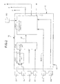
- a plurality of sensor or detector devices labelled S1 to SN is connected to the electronic control unit 10.
- a first group S1-Sn of such sensors is connected to corresponding inputs of a first correlation unit labelled CU1 in Figure 2.
- the sensors S1 to Sn supply the unit CU1 signals or data indicating the values or states of a plurality of operating parameters for the motor vehicle, such as the forward movement speed of the motor vehicle, the activated or non-activated condition of the motor vehicle's braking system, the rotation angle of the steering wheel and/or the transverse acceleration of the motor vehicle, the position of the accelerator pedal, the rotation speed or number of revolutions per unit of time of the motor vehicle's internal combustion engine, and signals indicating the gear ratio implemented by the gearbox of the motor vehicle.
- the correlation unit CU1 is arranged in a known manner per se to calculate, based on information from the sensors S1-Sn, the values of some quantities or parameters that are used subsequently in the control unit 10.
- the unit CU1 is arranged to calculate, for example, the following quantities:
- the unit CU1 is arranged to determine or estimate, according to predetermined procedures, the value of a predefined index I M able to identify the type of journey or mission of the motor vehicle, from a plurality of predefined types of journey or mission.
- the types of journey or mission may, for example, be the following:
- the signals or data representing the value determined for the index I M are supplied to the input of a second correlation unit CU2 (electrical correlation).
- a further plurality of sensors Sn+1-Sm that supply it signals or data indicating the values or states of a further plurality of operating parameters for the electrical system of the motor vehicle (currents, voltages, temperatures).
- the correlation unit CU2 is arranged to calculate, based on information from these sensors, the values of some electrical parameters or quantities that are used subsequently in the control unit 10.
- the unit CU2 is arranged to calculate, for example, the following quantities:
- the correlation unit CU2 Based on the signals or data supplied by the sensors Sn+1, ..., Sm and on the value of the index I M identifying the current type of journey or mission of the motor vehicle, the correlation unit CU2 supplies at its output signals or data indicating the value of an index M identifying the current operating condition or mode of the motor vehicle, from a plurality of predefined operating conditions or modes such as drive mode (normal running), park mode (when parked), crank request mode (startup request), logistic mode (when parked for extended periods), limp home mode (recovery when the vehicle is partially broken down), etc.
- drive mode normal running
- park mode when parked
- crank request mode startup request
- logistic mode when parked for extended periods
- limp home mode recovery when the vehicle is partially broken down
- the signals or data M indicating the current operating mode of the motor vehicle reach a processing and control unit labelled PCU in Figure 2.
- sensors Sm+1 ... SN are connected to the unit PCU, one of which (Sm+1) supplies, in particular, signals or data indicating the state of charge SOC of the battery 3.
- the processing and control unit PCU Based on the current operating mode M of the motor vehicle and on the signals supplied by the sensors Sm+1, ..., SN, the processing and control unit PCU generates control signals for the voltage regulator 2 associated with the generator 1, the management unit 4 associated with the battery 3 and the unit 8 for driving the switches associated with the non-priority loads 5.
- the non-priority electrical loads 5 can be conveniently managed as follows. For each non-priority load 5 which is active at a given moment, the processing and control unit PCU is predisposed to determine, as a function of the current operating mode M of the motor vehicle, the current state of charge SOC of the battery 3 and the time elapsed since the last activation of the load, a respective pair of values I 1 , I 2 (with I 1 ⁇ I 2 ) between which the current I supplied by the battery 3 must fall.
- the current supplied to the specific non-priority load is reduced (or even nullified) or is increased, depending on whether it is I>I 2 or I ⁇ I 1 , taking possibly also into account a priority index assigned to each non-priority load (such as the index P described in the following), in such a way as to tend to keep the current supplied by the battery within the desired interval.
- This management technique ensures a rapid intervention, limiting to a minimum the load deactivations needed to bring the battery to the optimum utilization area.
- each non-priority load is activated and deactivated independently of the others, merely on the basis of the SOC or at most following a priority table. Moreover, many loads can be simultaneously deactivated, sometimes without an actual need, and the battery current is not immediately reduced.
- the above-described management technique of a system according to the invention allows to limit or deactivate loads only to the strictly necessary extent, achieving an almost immediate effect onto the battery current.
- the processing and control unit PCU has another output, labelled 11 in Figure 2, which is intended to be connected to an electronic control unit of the motor vehicle's internal combustion engine.
- the unit PCU is able to send to the engine's electronic control unit signals aimed at obtaining an increase in the number of revolutions per unit of time for the internal combustion engine when idling, when it is necessary to increase the supply by the generator 1 and 2 to reduce the absorption of current that is dependent on the battery 3.
- the unit PCU executes, based on the current operating condition M of the motor vehicle, indicated by the correlation unit CU2, and based on the energy state of the generator equipment 1-3, corresponding predetermined methods of intervention.
- the unit PCU is arranged to execute, for example, three different types of intervention depending on whether the state of charge SOC of the battery 3 is "low", "normal” or "high".
- the unit PCU via the output 11 requests an increase in the rotation speed of the engine when idling and if necessary triggers a controlled reduction of absorption by the non-priority loads 5 via the associated controlled switches 7, all this aiming to reduce as far as possible the absorbed current that is dependent on the storage battery 3.
- the absorption by one or more non-priority loads 5 can be reduced by means of an actual interruption of the supply of current to this or these loads, or through a reduction in the intensity of the current supplied and/or via a delayed start of the electrical supply with respect to the command issued by the user.
- energy can be supplied to non-priority loads in general according to variable patterns that vary with time, which patterns can be defined each time through specific values assigned to a plurality of parameters. This will become clearer below with the description of Figure 3.
- the unit PCU then attends to managing the generator 1 via the regulator 2 so as to reach and maintain a state of charge SOC of the battery 3 that is substantially constant and equal to a preset value. This also has the effect of preventing phenomena of overcharging of the battery.
- the unit PCU controls the regulator 2 so as to maintain the battery 3 at a predefined constant voltage, if necessary causing the battery to discharge until its voltage reaches the target value.
- the unit PCU in the crank request operating mode, if the state of charge SOC of the battery 3 is "low", the unit PCU, through the controlled switches 7, causes non-priority loads 5 to be disconnected. If the state of charge of the battery 3 worsens, as a result of attempts to start the combustion engine, the unit PCU can in the worst case cause a reduction in the supply of energy to the priority loads 6, so as to preserve a residual starting capacity.
- control unit 10 is arranged to drive the controlled switches 7 such that the energy E supplied to a non-priority load 5 exhibits a variable pattern that varies with time, for example according to the solid-line curve of Figure 3.
- a time-varying pattern can be defined using the values assigned, each time, to a plurality of energy supply control parameters, for example those which will now be described with reference to Figure 3.
- the substantially rectangular curve in dotted line A represents a supply of electrical energy E to a generic non-priority load, which would occur when a user (driver or passenger) initiates an activation command at an instant t i , and until a deactivation command is issued at a final instant t f .
- the solid line curve B represents instead a time-varying pattern of a supply of energy to a non-priority load, brought about by the associated controlled switch 7 controlled by the electronic control unit 10.
- Such a pattern provides for a rising slope B1 the start of which is delayed by a time t D with respect to the instant t i of activation of the load by the user.
- the rising slope B1 exhibits a gradient ⁇ corresponding to the rate of increase with time of the energy E supplied to the non-priority load.
- the rising slope B1 is followed by a horizontal line B2, which corresponds to a supply of energy E at the maximum value, this maximum value being substantially equal to the constantly supplied value according to the curve A.
- the line B2 has a duration t M .
- the gradient ⁇ of which corresponds to the rate of decrease with time of the energy supplied to the non-priority load between the maximum value corresponding to the line B2 and an intermediate value corresponding to the next line B4 of the pattern B.
- the "jump" or difference between the levels of energy supplied to the non-priority load at the start and at the end of the falling slope B3 is indicated as ⁇ E.
- the pattern B can (in a limiting case) be brought to coincide with the pattern A, or (in the opposite limiting case) result in the load not being supplied.
- the values assigned to the abovementioned parameters are such that the pattern B delimits, with respect to the time axis t, an area less than that enclosed by the "rectangle" of the pattern A.
- the total of the areas included between the t axis and patterns A and B represents the energy saving achieved when the supply of a generic non-priority load 5 is controlled according to the pattern B.
- the processing and control unit PCU with regard to the various possible combinations of conditions or operating modes of the motor vehicle and energy states of the generation equipment 1-3, the specific values to be assigned to the parameters described above in order to define the extent of the reduction or delay or in the worst case the interruption of the supply of energy to each non-priority load are memorized.
- the unit PCU can be conveniently arranged to assign to the abovementioned energy supply control parameters values that are variable according to predetermined procedures based on further predetermined quantities that are monitored, such as environmental parameters (external temperature, presence of precipitation, etc.).
- the processing and control unit PCU can be conveniently arranged to assign, to each non-priority load 5, a respective priority index P according to a predetermined function of parameters indicating on the one hand the specific energy requirements of the load, and on the other hand the degree of impact of this load on the comfort perceived by the user of the motor vehicle.
- E a represents the energy "weight" of the individual load
- C is an index for the comfort perceived by the user in relation to the individual load
- k 1 and k 2 are predetermined multiplicative coefficients.
- control unit 10 acts on the non-priority loads based on their values of the priority index P.
- the coefficient k 2 associated with the degree of perceived comfort C for each non-priority load may be conveniently modified ("customized") by the same user.
- a setting device SD enabling the user to assign a weight k 2 for the comfort index C to individual non-priority loads 5 according to the user's personal subjective taste.
Landscapes
- Engineering & Computer Science (AREA)
- Mechanical Engineering (AREA)
- Power Engineering (AREA)
- Electric Propulsion And Braking For Vehicles (AREA)
- Charge And Discharge Circuits For Batteries Or The Like (AREA)
- Control Of Charge By Means Of Generators (AREA)
Applications Claiming Priority (1)
| Application Number | Priority Date | Filing Date | Title |
|---|---|---|---|
| EP05425732A EP1777116A1 (de) | 2005-10-19 | 2005-10-19 | Ein System zur Verwaltung der Versorgung elektrischer Energie in einem Kraftfahrzeug |
Publications (2)
| Publication Number | Publication Date |
|---|---|
| EP1777119A2 true EP1777119A2 (de) | 2007-04-25 |
| EP1777119A3 EP1777119A3 (de) | 2007-09-12 |
Family
ID=36062918
Family Applications (2)
| Application Number | Title | Priority Date | Filing Date |
|---|---|---|---|
| EP05425732A Withdrawn EP1777116A1 (de) | 2005-10-19 | 2005-10-19 | Ein System zur Verwaltung der Versorgung elektrischer Energie in einem Kraftfahrzeug |
| EP06122480A Withdrawn EP1777119A3 (de) | 2005-10-19 | 2006-10-18 | Ein System zur Verwaltung der Versorgung elektrischer Energie in einem Kraftfahrzeug |
Family Applications Before (1)
| Application Number | Title | Priority Date | Filing Date |
|---|---|---|---|
| EP05425732A Withdrawn EP1777116A1 (de) | 2005-10-19 | 2005-10-19 | Ein System zur Verwaltung der Versorgung elektrischer Energie in einem Kraftfahrzeug |
Country Status (3)
| Country | Link |
|---|---|
| US (1) | US20070102212A1 (de) |
| EP (2) | EP1777116A1 (de) |
| CN (1) | CN1967967A (de) |
Families Citing this family (33)
| Publication number | Priority date | Publication date | Assignee | Title |
|---|---|---|---|---|
| CN101293485B (zh) * | 2007-04-27 | 2011-01-26 | 杰生自动技术有限公司 | 一种交通工具外接电器电力管理方式及其装置 |
| US8010250B2 (en) | 2007-06-05 | 2011-08-30 | The Boeing Company | Life-optimal power management methods for battery networks system |
| US8560124B2 (en) * | 2007-07-13 | 2013-10-15 | Cummins Inc. | Idle control system and method for adaptive temperature control |
| CN101109349B (zh) * | 2007-08-07 | 2010-05-26 | 力帆实业(集团)股份有限公司 | 摩托车ecu延时处理电路 |
| US20100016034A1 (en) * | 2008-06-10 | 2010-01-21 | Telefonaktiebolaget L M Ericsson (Publ) | Power supply method and apparatus for radio access network nodes/sites |
| JP4780190B2 (ja) * | 2008-12-26 | 2011-09-28 | トヨタ自動車株式会社 | ブレーキ制御装置 |
| DE102009006846B4 (de) * | 2009-01-30 | 2013-06-06 | Audi Ag | Verfahren zur Steuerung mehrerer Verbraucher eines Kraftfahrzeuges |
| KR101086974B1 (ko) * | 2009-03-03 | 2011-11-29 | 주식회사 엘지화학 | 전기구동차량의 릴레이 제어 장치 및 방법 |
| DE102009028965A1 (de) | 2009-08-28 | 2011-03-03 | Robert Bosch Gmbh | Schaltung zum Betreiben eines Hilfsaggregat für den Start von Verbrennungsmaschinen |
| JP2011172318A (ja) * | 2010-02-16 | 2011-09-01 | Omron Automotive Electronics Co Ltd | 電源システムおよび電源制御方法 |
| JP5220046B2 (ja) * | 2010-02-23 | 2013-06-26 | 本田技研工業株式会社 | 車両状態監視サーバおよび車両状態監視システム |
| CN101826747B (zh) * | 2010-03-19 | 2012-09-19 | 艾默生网络能源有限公司 | 一种通信电源电路 |
| FR2959813B1 (fr) * | 2010-05-04 | 2012-07-06 | Peugeot Citroen Automobiles Sa | Jauge d'energie a longueur variable |
| JP5196011B2 (ja) * | 2010-06-11 | 2013-05-15 | トヨタ自動車株式会社 | 充電制御システム |
| DE102011011252A1 (de) * | 2011-02-15 | 2012-08-16 | GM Global Technology Operations LLC (n. d. Ges. d. Staates Delaware) | Lastenträgersystem für ein Kraftfahrzeug mit integrierter Energieversorgungseinrichtung |
| FR2989779B1 (fr) * | 2012-04-19 | 2015-02-06 | Commissariat Energie Atomique | Dispositif de determination d'une caracteristique d'une batterie et procede de fonctionnement d'un tel dispositif |
| JP5753138B2 (ja) * | 2012-08-28 | 2015-07-22 | 株式会社日立製作所 | 負荷管理機能を備えた車両情報制御装置 |
| CN105102791B (zh) * | 2013-04-01 | 2016-12-21 | 丰田自动车株式会社 | 充电控制装置、车辆控制装置、车辆、充电控制方法以及车辆控制方法 |
| DE102014219138A1 (de) * | 2014-09-23 | 2016-03-24 | Robert Bosch Gmbh | Bordnetz |
| DE102014015883B4 (de) * | 2014-10-27 | 2020-12-24 | Audi Ag | Kraftfahrzeug und Verfahren zum Betreiben von wenigstens zwei kraftfahrzeugseitigen elektrischen Verbrauchern |
| JP6583009B2 (ja) * | 2016-01-19 | 2019-10-02 | スズキ株式会社 | 車両の充放電装置 |
| DE102016222699A1 (de) * | 2016-11-18 | 2018-05-24 | Robert Bosch Gmbh | Verfahren und Vorrichtung zur Regelung der Leistung eines elektrischen Verbrauchers |
| KR101936995B1 (ko) | 2016-11-25 | 2019-01-10 | 현대자동차주식회사 | 모터 제어 방법 및 시스템 |
| DE102016015512A1 (de) * | 2016-12-23 | 2018-06-28 | Bayerische Motoren Werke Ag | Elektrisches Energiemanagement eines Bordsystems eines Kraftfahrzeuges |
| CN107546827B (zh) * | 2017-08-16 | 2020-10-23 | 湖北华中光电科技有限公司 | 一种车载电源的电力补偿电路 |
| FR3085322B1 (fr) * | 2018-08-28 | 2023-10-06 | Renault Sas | Circuit electrique, et vehicule automobile comprenant un tel circuit |
| JP2020111278A (ja) * | 2019-01-16 | 2020-07-27 | 株式会社デンソー | 車両用制御ユニット |
| ES2992855T3 (en) * | 2019-09-09 | 2024-12-19 | Thermo King Llc | Prioritized power delivery for facilitating transport climate control |
| US11371573B2 (en) * | 2020-03-09 | 2022-06-28 | GM Global Technology Operations LLC | Methods and systems for EMI assessment for brake pad wear estimation |
| CN113803183B (zh) * | 2020-06-11 | 2024-07-05 | 科勒公司 | 发动机系统以及启动发动机的方法 |
| CN111722112B (zh) * | 2020-06-23 | 2022-12-20 | 深圳市道通科技股份有限公司 | 一种电池检测方法及设备 |
| KR102456982B1 (ko) * | 2020-12-15 | 2022-10-20 | 현대모비스 주식회사 | 차량의 전원장치 |
| CN222016254U (zh) * | 2021-06-18 | 2024-11-15 | 武汉领普科技有限公司 | 供电电路、传感设备与传感系统 |
Family Cites Families (10)
| Publication number | Priority date | Publication date | Assignee | Title |
|---|---|---|---|---|
| DE3936638C1 (en) * | 1989-11-03 | 1991-03-14 | Mercedes-Benz Aktiengesellschaft, 7000 Stuttgart, De | Ensuring electrical power supply in motor vehicle - grouping electrical appliances according to their importance for safety of vehicle |
| DE19745849A1 (de) * | 1997-10-16 | 1999-04-22 | Bosch Gmbh Robert | Einrichtung zur Energieverteilung in einem Kraftfahrzeug |
| ITTO980325A1 (it) * | 1998-04-16 | 1999-10-16 | C R F Societa Conosrtile Per A | Sistema per il controllo automatico personalizzato del cambio di marcia in un autoveicolo provvisto di un cambio di velocita' |
| DE19844512C1 (de) * | 1998-09-28 | 2000-12-14 | Volkswagen Ag | Verfahren und Steuereinrichtung zur Reduzierung der Bordnetzbelastung eines Kraftfahrzeugs |
| US6718214B1 (en) * | 1998-12-15 | 2004-04-06 | Robert Bosch Gmbh | Method for switching consumer on or off |
| DE19857916A1 (de) * | 1998-12-15 | 2000-06-21 | Bosch Gmbh Robert | Verfahren und Vorrichtung zur Steuerung von elektrischen Verbrauchern in einem Fahrzeug |
| WO2001018932A1 (en) * | 1999-09-10 | 2001-03-15 | Intra International Ab | Intelligent power management system |
| GB2360644B (en) * | 2000-03-22 | 2004-09-15 | Jaguar Cars | Motor vehicle electrical load management |
| JP2003061400A (ja) * | 2001-08-20 | 2003-02-28 | Nissan Motor Co Ltd | 車両用発電機の制御装置 |
| US6745117B1 (en) * | 2003-05-16 | 2004-06-01 | Deere & Company | Power-limiting control method and system for a work vehicle |
-
2005
- 2005-10-19 EP EP05425732A patent/EP1777116A1/de not_active Withdrawn
-
2006
- 2006-10-18 EP EP06122480A patent/EP1777119A3/de not_active Withdrawn
- 2006-10-19 CN CNA2006101486811A patent/CN1967967A/zh active Pending
- 2006-10-19 US US11/550,864 patent/US20070102212A1/en not_active Abandoned
Also Published As
| Publication number | Publication date |
|---|---|
| EP1777116A1 (de) | 2007-04-25 |
| EP1777119A3 (de) | 2007-09-12 |
| CN1967967A (zh) | 2007-05-23 |
| US20070102212A1 (en) | 2007-05-10 |
Similar Documents
| Publication | Publication Date | Title |
|---|---|---|
| EP1777119A2 (de) | Ein System zur Verwaltung der Versorgung elektrischer Energie in einem Kraftfahrzeug | |
| CN102077147B (zh) | 车辆的速度调节系统 | |
| US11505071B2 (en) | Regenerative braking control method and regenerative braking control device | |
| US7798578B2 (en) | Driver feedback to improve vehicle performance | |
| JP3164821B2 (ja) | 動力/電力変換器及び加速レバーを有する軌道非拘束型車両 | |
| CN110979018A (zh) | 车辆及其控制方法和装置、电子设备、存储介质 | |
| CN111231688A (zh) | 车辆及控制车辆的方法 | |
| CN103121450A (zh) | 一种纯电动汽车的坡道控制方法 | |
| JP2008228403A (ja) | 車両用電源装置 | |
| JP2009138647A (ja) | 制御システム及び制御方法 | |
| JP2007276542A (ja) | 車両用走行制御装置 | |
| US10059337B2 (en) | Cruise control apparatus | |
| JP5661166B1 (ja) | 車両用充電システム | |
| EP2212148A1 (de) | Verfahren zur effizienteren verwendung eines verbrennungsmotors in einem fahrzeug | |
| JP2000006683A (ja) | 車両用走行速度制御システム | |
| JP4497145B2 (ja) | 車両用発電機の制御装置 | |
| JPH099411A (ja) | 電気自動車の走行用モータ制御装置 | |
| EP3201058B1 (de) | Von einer steuereinheit zur steuerung von energieflüssen eines fahrzeugs ausgeführtes verfahren | |
| US6424110B1 (en) | Electric vehicle control system | |
| JP2005094865A (ja) | ハイブリッド車両及びそのシステム | |
| KR102331792B1 (ko) | 차량 추진 시스템 및 차량 추진 방법 | |
| JPH0156617B2 (de) | ||
| CN121084187A (zh) | 电动挂车与主车的协同控制方法、系统及车辆 | |
| SE546276C2 (en) | Control device and method for controlling a look-ahead cruise control of a vehicle | |
| KR100623748B1 (ko) | 4륜 하이브리드 전기자동차의 아이들 발전 토크 제어방법 |
Legal Events
| Date | Code | Title | Description |
|---|---|---|---|
| PUAI | Public reference made under article 153(3) epc to a published international application that has entered the european phase |
Free format text: ORIGINAL CODE: 0009012 |
|
| AK | Designated contracting states |
Kind code of ref document: A2 Designated state(s): AT BE BG CH CY CZ DE DK EE ES FI FR GB GR HU IE IS IT LI LT LU LV MC NL PL PT RO SE SI SK TR |
|
| AX | Request for extension of the european patent |
Extension state: AL BA HR MK YU |
|
| RIN1 | Information on inventor provided before grant (corrected) |
Inventor name: IDONE, DOMENICO |
|
| PUAL | Search report despatched |
Free format text: ORIGINAL CODE: 0009013 |
|
| AK | Designated contracting states |
Kind code of ref document: A3 Designated state(s): AT BE BG CH CY CZ DE DK EE ES FI FR GB GR HU IE IS IT LI LT LU LV MC NL PL PT RO SE SI SK TR |
|
| AX | Request for extension of the european patent |
Extension state: AL BA HR MK YU |
|
| AKX | Designation fees paid | ||
| REG | Reference to a national code |
Ref country code: DE Ref legal event code: 8566 |
|
| STAA | Information on the status of an ep patent application or granted ep patent |
Free format text: STATUS: THE APPLICATION IS DEEMED TO BE WITHDRAWN |
|
| 18D | Application deemed to be withdrawn |
Effective date: 20080313 |