EP1777145B1 - Agencement de pare-brise - Google Patents
Agencement de pare-brise Download PDFInfo
- Publication number
- EP1777145B1 EP1777145B1 EP20060021586 EP06021586A EP1777145B1 EP 1777145 B1 EP1777145 B1 EP 1777145B1 EP 20060021586 EP20060021586 EP 20060021586 EP 06021586 A EP06021586 A EP 06021586A EP 1777145 B1 EP1777145 B1 EP 1777145B1
- Authority
- EP
- European Patent Office
- Prior art keywords
- windshield
- cover
- arrangement according
- breaking point
- predetermined breaking
- Prior art date
- Legal status (The legal status is an assumption and is not a legal conclusion. Google has not performed a legal analysis and makes no representation as to the accuracy of the status listed.)
- Not-in-force
Links
- 239000000463 material Substances 0.000 claims description 8
- 238000010276 construction Methods 0.000 description 7
- 230000006378 damage Effects 0.000 description 7
- 208000027418 Wounds and injury Diseases 0.000 description 5
- 208000014674 injury Diseases 0.000 description 5
- 239000000969 carrier Substances 0.000 description 3
- 230000000694 effects Effects 0.000 description 2
- 238000010521 absorption reaction Methods 0.000 description 1
- 238000005452 bending Methods 0.000 description 1
- 239000011248 coating agent Substances 0.000 description 1
- 238000000576 coating method Methods 0.000 description 1
- 230000001419 dependent effect Effects 0.000 description 1
- 238000001514 detection method Methods 0.000 description 1
- 230000009977 dual effect Effects 0.000 description 1
- 238000005516 engineering process Methods 0.000 description 1
- 238000003780 insertion Methods 0.000 description 1
- 230000037431 insertion Effects 0.000 description 1
- 238000002955 isolation Methods 0.000 description 1
- 239000002184 metal Substances 0.000 description 1
- 238000012986 modification Methods 0.000 description 1
- 230000004048 modification Effects 0.000 description 1
- 238000000465 moulding Methods 0.000 description 1
- 230000002787 reinforcement Effects 0.000 description 1
- 230000035939 shock Effects 0.000 description 1
- 239000007787 solid Substances 0.000 description 1
- 230000000007 visual effect Effects 0.000 description 1
Images


Classifications
-
- B—PERFORMING OPERATIONS; TRANSPORTING
- B62—LAND VEHICLES FOR TRAVELLING OTHERWISE THAN ON RAILS
- B62D—MOTOR VEHICLES; TRAILERS
- B62D25/00—Superstructure or monocoque structure sub-units; Parts or details thereof not otherwise provided for
- B62D25/04—Door pillars ; windshield pillars
-
- B—PERFORMING OPERATIONS; TRANSPORTING
- B60—VEHICLES IN GENERAL
- B60R—VEHICLES, VEHICLE FITTINGS, OR VEHICLE PARTS, NOT OTHERWISE PROVIDED FOR
- B60R21/00—Arrangements or fittings on vehicles for protecting or preventing injuries to occupants or pedestrians in case of accidents or other traffic risks
- B60R21/34—Protecting non-occupants of a vehicle, e.g. pedestrians
-
- B—PERFORMING OPERATIONS; TRANSPORTING
- B60—VEHICLES IN GENERAL
- B60R—VEHICLES, VEHICLE FITTINGS, OR VEHICLE PARTS, NOT OTHERWISE PROVIDED FOR
- B60R21/00—Arrangements or fittings on vehicles for protecting or preventing injuries to occupants or pedestrians in case of accidents or other traffic risks
- B60R21/34—Protecting non-occupants of a vehicle, e.g. pedestrians
- B60R2021/343—Protecting non-occupants of a vehicle, e.g. pedestrians using deformable body panel, bodywork or components
Definitions
- the invention is in the field of impact and crash optimized design of the front area of motor vehicles and relates to a windshield assembly for a passenger vehicle according to the preamble of patent claim 1.
- EP 1 479 574 A1 Such an arrangement is the European Patent Application EP 1 479 574 A1 removable, which relates to an outwardly acting airbag, which unfolds in a detected by a sensor external impact of an object by means of guide rails in defined covering zones around the windshield.
- the outer cover of the airbag is partially torn open by a cover member is torn open along a defined spoiler edge.
- German patent application DE 100 59 694 A1 is directed to the shock absorbing effect of an A-pillar in case of collision.
- sufficient movement space is provided for the deforming A-pillar, in that upon detection of an impact the front door in the area of the A-pillar forcibly pivots out of the deformation movement direction of the A-pillar.
- the visual range of the lateral windshield carrier (A-pillar) is integrated into the vehicle side wall and welded to an internal reinforcement such that forms a relatively stiff profile.
- the distance between the windscreen carriers increases towards the hood.
- the vehicle side wall contour has aerodynamic reasons and due to the vehicle design often small bending radii, which are relatively sharp.
- the present invention is based on the object, the windshield assembly of a passenger car to be improved so that impact-related serious damage is largely avoided in impact situations, especially in the impact of passers-by in the windshield area of the vehicle.
- each side windshield support is frontally covered by a panel and that the panel has at least one predetermined breaking point.
- the idea underlying the present invention is, inter alia, to consciously integrate an energy-consuming zone into the diaphragm (s).
- the diaphragm breaks or collapses upon impact of an object or a person and the associated exceeding of the load threshold defined at the predetermined breaking point. Due to the deformation and the breakage of the diaphragm, an energy absorption takes place, which at least partially consumes the impact energy and thus reduces or at best avoids any damage to persons or objects or to the passenger car itself.
- the windshield support structure per se in conventional construction, in particular in so-called shell construction or as a pipe profile, executed.
- An essential advantage of the windshield assembly according to the invention is thus that under Using conventional, proven vehicle designs at least a significant proportion of impact forces acting on the impact force is absorbed by the fact that the panel breaks at its at least one predetermined breaking point.
- care can be taken to ensure that no sharp, an additional risk of injury representing breaking edges occur during the predetermined breakage to the outside.
- the predetermined breaking point consists of at least one recess in the material of the diaphragm.
- the predetermined breaking point or the material recess extends in the direction of the windshield carrier, ie substantially between the roof area and the engine area of the vehicle.
- the predetermined breaking point is formed in an inner side region of the diaphragm, preferably along a diaphragm edge.
- the predetermined breaking point can preferably be channel-shaped or groove-shaped.
- a particularly effective energy-absorbing effect has the aperture of the windshield assembly according to the invention when, according to a preferred embodiment of the invention, the windshield support to the vehicle front not extend beyond the surface of the windshield out.
- the panels are energy-consuming Elements effective, so that no isolated, injury-causing hard impact on the windshield or the carrier can take place.
- the panel is attached to a body-side mounting bracket.
- the mounting bracket may preferably be made of sheet metal or plastic and both in the shell or only in the final assembly to the windshield support (A-pillar structure) are attached.
- the attachment of the mounting bracket to the body is preferably carried out by means of riveted joints.
- the mounting bracket has a plurality of recesses, engage in the corresponding mounting hook of the panel.
- the mounting hooks can preferably engage in the corresponding recesses, so that the panel is firmly held by the mounting bracket.
- this can additionally - preferably in the front area of the vehicle, for example, below the Wasserabweisers - connected to the vehicle body, for example, be screwed.
- the mounting hooks are arranged in the vehicle outer side facing, lateral area of the panel. You are thus relatively far out in the sloping area of the windshield carrier (ie the A-pillar contour). So they are located outside the immediate impact area in a collision, whereby the endangerment of Aufprallopfers is further reduced by the mounting hooks.
- the aperture is preferably made of plastic.
- FIG. 1 shows a side view of the side body portion of a passenger car body with a running in the front area side windshield carrier 1, which is usually - also referred to below - as A-pillar.
- the A-pillar can be like in FIG. 1 illustrated have two sub-carriers 1a and 1b, between which a so-called triangular window 2 can be arranged.
- the A-pillar extends from a front area 3 to the roof area 4 of the vehicle body.
- FIG. 1 Invisible opposite vehicle side is constructed to the vehicle longitudinal plane substantially mirror-image and includes a corresponding windshield carrier (A-pillar).
- A-pillar windshield carrier
- the two vehicle body sides are connected to each other to form a windshield frame 5.
- Each A-pillar 1 is covered towards the front side 3, each with a diaphragm 8 (in FIG. 1 again only one aperture 8 of the left-side A-pillar 1 can be seen, which extends along the partial support 1a).
- FIG. 2 The Figures 2 and 3 show that the A-pillar in conventional shell construction ( FIG. 2 ) or as a tube profile ( FIG. 3 ) can be executed.
- the windshield 9 extends with a certain frontal distance 10 to the A-pillar 1.
- This is formed from a half-shell 11, which is welded to the outer side wall 12 to form a profile 14.
- the profile 14 is rigid and rigid, so that it can hardly yield in a frontal impact of an object or a person. Therefore, the impact energy in a collision could lead to significant damage - especially personal injury - lead.
- the A-pillar (windshield support 1) is covered by the panel 8, with one leg 8a along the receptacle 19 for the triangular window 2 and with another leg 8b approximately at right angles to the windshield 9 and substantially along the A-pillar 1 extends.
- a decorative strip 20 is provided to the windshield 9 out .
- the A-pillar 1 is concealed by an inner pillar panel 24.
- the windshield frame 5 which is introduced into the windshield frame 5, for example glued in, projects beyond the lateral A-pillars 1 with its outside surface 9a.
- the A-pillars extend back behind the windshield outside.
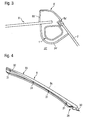
- FIG. 3 shows a substantially corresponding to the figure embodiment, in which case the A-pillar 1 'is formed by a tube profile. This profile is to the passenger compartment 22 'of an inside cover 24' covered. Laterally, the triangular window pane 2 can be seen, at the front edge of which the leg 8a 'of a panel 8' extends in the manner described above. The other leg 8b 'is similar to that in FIG FIG. 2 shown arranged and thus surrounds the lateral end of the windshield 9 '.
- FIG. 4 shows in isolation a diaphragm 8 as in the embodiment of the FIGS. 1, 2 or 3 can be used.
- the panel 8 has at its front, in the assembled state front, the engine compartment end 28 facing a flange 30, which serves for screwing to the body. Furthermore, a plurality of mounting hooks 31 can be seen, which are arranged in the vehicle outer side 32 side facing the side region 33 of the panel. They are - in the assembled state of the panel - so relatively far outward in the sloping area of the A-pillar and thus outside the immediate impact area in a collision. As a result, the endangerment of the collision victim is reduced by the mounting hooks.
- the panel 8 may preferably be made of plastic and coated on its outer, design-effective upper side 8c and / or painted.
- FIG. 5 shows the aperture 8 again (like the Figures 2 and 3 ) in cross-section to illustrate the placement and insertion of a predetermined breaking point 35.
- a clear material recess 38 can be seen in the inner region 36 of a diaphragm edge 8d. These extend along the aperture 8 in the longitudinal direction and thus substantially parallel to the respective A-pillar 1 Material recess is formed here, for example, channel-shaped.
- the panel In the event of an impact of an object or a person on the front windshield area of the vehicle, the panel would deform when exceeding a certain load at the predetermined breaking point and, for example, buckle inwards.
- the main part 8e of the diaphragm can be detached from the remaining part 8f or at least deformed by buckling. This advantageously consumes a considerable amount of the impact energy (impact energy) which occurs during the impact and causes injury. This significantly reduces the impact on the object or person.
- FIG. 6 Finally shows a mounting bracket 40 which is fixedly connected to the vehicle body, for example by riveting.
- the mounting bracket faces the mounting hooks 31 (FIG. FIG. 4 ) corresponding recesses 41, which are designed in shape so that the mounting hooks 31 can slide into the recesses and lock there.
- the mounting hooks 31 For a solid, yet releasable attachment of the panel is secured to the mounting bracket 40. This allows the panel to be replaced very easily, for example during repair after a collision.
- the diaphragm which is preferably made of plastic, can also serve the appealing design of the vehicle in a dual function and allows to maintain conventional designs of the A-pillar in shell construction or as a tube profile without significant weight increase.
Landscapes
- Engineering & Computer Science (AREA)
- Mechanical Engineering (AREA)
- Chemical & Material Sciences (AREA)
- Combustion & Propulsion (AREA)
- Transportation (AREA)
- Body Structure For Vehicles (AREA)
Claims (11)
- Dispositif de pare-brise pour un véhicule à moteur personnel avec un pare-brise (9) qui s'étend entre deux supports de pare-brise latéraux (1),
dans lequel chaque support de pare-brise latéral (1) est recouvert sur l'avant par un volet (8),
caractérisé en ce que le volet (8) présente une zone absorbant l'énergie en cela qu'il est prévu au moins un point de rupture nominal (35) il le volet se brise ou s'enfonce de façon définie en cas d'impact d'un objet dépassant une limite de contrainte, le point de rupture nominal (35) étant formé par au moins un évidement de matériau (38) dans le matériau du volet (8). - Dispositif de pare-brise selon la revendication 1, caractérisé en ce que le point de rupture nominal (35) s'étend pour l'essentiel le long du support de pare-brise (1).
- Dispositif de pare-brise selon la revendication 2, caractérisé en ce que le point de rupture nominal (35) est formé dans la zone (36) intérieure du côté du volet d'un coin de volet (8d).
- Dispositif de pare-brise selon l'une au moins des revendications précédentes, caractérisé en ce que le point de rupture nominal (35) est en forme de rainure ou d'auge.
- Dispositif de pare-brise selon l'une au moins des revendications précédentes, caractérisé en ce que les supports de pare-brise (1) ne s'étendent pas au-delà de la surface (9a) du pare-brise (9) vers l'avant (3) du véhicule.
- Dispositif de pare-brise selon l'une au moins des revendications précédentes, caractérisé en ce que le volet (8) est fixé à un support de montage (40) situé du côté de la carrosserie.
- Dispositif de pare-brise selon la revendication 6, caractérisé en ce que le support de montage (40) est relié à la carrosserie par des rivets.
- Dispositif de pare-brise selon l'une au moins des revendications 6 ou 7, caractérisé en ce que le support de montage (40) présente plusieurs évidements (41) dans lesquels des crochets de montage (31) correspondants du volet (8) se mettent en prise.
- Dispositif de pare-brise selon la revendication 8, caractérisé en ce que les crochets de montage (31) engrènent dans les évidements (41) correspondants.
- Dispositif de pare-brise selon la revendication 8 ou 9, caractérisé en ce que les crochets de montage (31) sont disposés dans la partie latérale (33) du volet (8) tournée vers l'extérieur du véhicule.
- Dispositif de pare-brise selon l'une au moins des revendications précédentes, caractérisé en ce que le volet (8) est composé de plastique.
Applications Claiming Priority (1)
| Application Number | Priority Date | Filing Date | Title |
|---|---|---|---|
| DE200510049945 DE102005049945A1 (de) | 2005-10-19 | 2005-10-19 | Windschutzscheibenanordnung |
Publications (2)
| Publication Number | Publication Date |
|---|---|
| EP1777145A1 EP1777145A1 (fr) | 2007-04-25 |
| EP1777145B1 true EP1777145B1 (fr) | 2012-06-27 |
Family
ID=37654903
Family Applications (1)
| Application Number | Title | Priority Date | Filing Date |
|---|---|---|---|
| EP20060021586 Not-in-force EP1777145B1 (fr) | 2005-10-19 | 2006-10-14 | Agencement de pare-brise |
Country Status (2)
| Country | Link |
|---|---|
| EP (1) | EP1777145B1 (fr) |
| DE (1) | DE102005049945A1 (fr) |
Families Citing this family (2)
| Publication number | Priority date | Publication date | Assignee | Title |
|---|---|---|---|---|
| DE102009057943A1 (de) * | 2009-12-11 | 2011-06-16 | GM Global Technology Operations LLC, ( n. d. Ges. d. Staates Delaware ), Detroit | Karosseriestruktursäule für ein Kraftfahrzeug und Kraftfahrzeug aufweisend eine Karosseriestruktursäule |
| JP7338498B2 (ja) * | 2020-02-10 | 2023-09-05 | トヨタ自動車株式会社 | 車両用ピラー構造 |
Family Cites Families (12)
| Publication number | Priority date | Publication date | Assignee | Title |
|---|---|---|---|---|
| DE2336375A1 (de) * | 1973-07-17 | 1974-02-21 | Nissan Motor | Windschutzscheibenbefestigung |
| DE3836687C2 (de) * | 1988-10-28 | 1995-11-09 | Audi Ag | Dachzierleiste für ein Kraftfahrzeug |
| GB2293798B (en) * | 1994-10-07 | 1998-03-04 | Toyota Motor Co Ltd | Occupant protecting structures of vehicle body upper portions |
| DE19506160B4 (de) * | 1995-02-22 | 2006-05-11 | Adam Opel Ag | Rahmenkonstruktion für Kraftfahrzeuge |
| EP1227968B1 (fr) * | 1999-10-28 | 2004-01-14 | Toyota Jidosha Kabushiki Kaisha | Structure de montant pour vehicule |
| JP2001163054A (ja) * | 1999-12-03 | 2001-06-19 | Honda Motor Co Ltd | 車両のフロントドア移動構造及び車両のドアガラス下降構造 |
| DE10106149A1 (de) * | 2001-02-10 | 2002-09-12 | Bayerische Motoren Werke Ag | Mittelsäule einer Kraftfahrzeugkarosserie |
| US6415883B1 (en) * | 2002-01-24 | 2002-07-09 | Ford Global Technologies, Inc. | Deployable A-pillar covers for pedestrian protection |
| JP2004338676A (ja) * | 2003-05-19 | 2004-12-02 | Takata Corp | 外面展開型エアバッグ装置 |
| DE10335030A1 (de) * | 2003-07-31 | 2005-03-03 | Daimlerchrysler Ag | Seitenwand für ein Fahrzeug |
| FR2859444B1 (fr) * | 2003-09-09 | 2006-02-03 | Plastic Omnium Cie | Utilisation d'aile et d'un capot en combinaison avec un coussin gonflable, moyen de retenue et support d'aile, aile, module d'aile et capot d'un vehicule automobile |
| DE202004010601U1 (de) * | 2004-04-08 | 2005-05-19 | Dura Automotive Plettenberg Entwicklungs- Und Vertriebs Gmbh | Säulenblende für ein Kraftfahrzeug |
-
2005
- 2005-10-19 DE DE200510049945 patent/DE102005049945A1/de not_active Ceased
-
2006
- 2006-10-14 EP EP20060021586 patent/EP1777145B1/fr not_active Not-in-force
Also Published As
| Publication number | Publication date |
|---|---|
| EP1777145A1 (fr) | 2007-04-25 |
| DE102005049945A1 (de) | 2007-04-26 |
Similar Documents
| Publication | Publication Date | Title |
|---|---|---|
| EP1981737B1 (fr) | Corps d absorption d énergie, dispositif de protection contre une collision, élément d habillage intérieur pour véhicule automobile et traverse | |
| EP2046627B1 (fr) | Bas de caisse lateral d'une carrosserie de vehicule automobile | |
| EP0426648B1 (fr) | Porte pour voiture automobile | |
| EP1840002B1 (fr) | Véhicule automobile avec un élément déformable pour absorber les chocs latéraux dans la zone latérale du véhicule | |
| EP1840005B1 (fr) | Carosserie d'un véhicule automobile avec une structure de traverse pour une zone d'assise du véhicule | |
| EP1090818B1 (fr) | Véhicule à moteur équipé avec un extrémité frontale aimable de piétons | |
| DE102004007571B4 (de) | Vorderwagen für ein Fahrzeug, insbesondere für ein Kraftfahrzeug | |
| DE102012020865A1 (de) | Kraftfahrzeugkarosserie | |
| DE102008009088B4 (de) | Karosserie eines Kraftfahrzeugs mit einem Seitenschweller | |
| DE102007014391B4 (de) | Seitenaufprallschutzeinrichtung, die zwischen Innen- und Außenbleche eingebaut ist | |
| EP1300323A2 (fr) | Elément de carrosserie de véhicule à section large | |
| DE10305652A1 (de) | Frontendbereich | |
| EP1216891A2 (fr) | Elément de déformation absorbeur d'énergie | |
| EP2239128B1 (fr) | Pièce de véhicule dotée d'un élément de renforcement de structure | |
| EP1777145B1 (fr) | Agencement de pare-brise | |
| DE102006030504B4 (de) | Stoßfänger für ein Kraftfahrzeug | |
| DE102004009665B4 (de) | A-Säule für eine Kraftfahrzeugkarosserie | |
| DE102009040602A1 (de) | Stoßfänger und Stoßfängerbaukasten | |
| DE102009012941A1 (de) | Sicherheitsvorrichtung am Bug der Karosserie von Personenkraftfahrzeugen | |
| DE202015001448U1 (de) | Fahrzeugsäule, insbesondere A-Säule für ein Kraftfahrzeug | |
| DE10309958A1 (de) | Kraftfahrzeug mit einer Fußgängerschutzeinrichtung sowie Verfahren zum Betreiben einer Fußgängerschutzeinrichtung an einem solchen Kraftfahrzeug | |
| DE102009012237B4 (de) | Karosserie für ein Kraftfahrzeug | |
| DE102010036985A1 (de) | Deformationselement | |
| DE102009006875B4 (de) | Karosserieseitenstruktur eines Kraftfahrzeugs | |
| DE10258299B4 (de) | Karosseriefronthaube für ein Kraftfahrzeug |
Legal Events
| Date | Code | Title | Description |
|---|---|---|---|
| PUAI | Public reference made under article 153(3) epc to a published international application that has entered the european phase |
Free format text: ORIGINAL CODE: 0009012 |
|
| AK | Designated contracting states |
Kind code of ref document: A1 Designated state(s): AT BE BG CH CY CZ DE DK EE ES FI FR GB GR HU IE IS IT LI LT LU LV MC NL PL PT RO SE SI SK TR |
|
| AX | Request for extension of the european patent |
Extension state: AL BA HR MK YU |
|
| 17P | Request for examination filed |
Effective date: 20071025 |
|
| AKX | Designation fees paid |
Designated state(s): AT BE BG CH CY CZ DE DK EE ES FI FR GB GR HU IE IS IT LI LT LU LV MC NL PL PT RO SE SI SK TR |
|
| 17Q | First examination report despatched |
Effective date: 20071218 |
|
| RAP1 | Party data changed (applicant data changed or rights of an application transferred) |
Owner name: GM GLOBAL TECHNOLOGY OPERATIONS LLC |
|
| GRAP | Despatch of communication of intention to grant a patent |
Free format text: ORIGINAL CODE: EPIDOSNIGR1 |
|
| GRAS | Grant fee paid |
Free format text: ORIGINAL CODE: EPIDOSNIGR3 |
|
| GRAA | (expected) grant |
Free format text: ORIGINAL CODE: 0009210 |
|
| AK | Designated contracting states |
Kind code of ref document: B1 Designated state(s): AT BE BG CH CY CZ DE DK EE ES FI FR GB GR HU IE IS IT LI LT LU LV MC NL PL PT RO SE SI SK TR |
|
| REG | Reference to a national code |
Ref country code: GB Ref legal event code: FG4D Free format text: NOT ENGLISH |
|
| REG | Reference to a national code |
Ref country code: CH Ref legal event code: EP |
|
| REG | Reference to a national code |
Ref country code: AT Ref legal event code: REF Ref document number: 564026 Country of ref document: AT Kind code of ref document: T Effective date: 20120715 |
|
| REG | Reference to a national code |
Ref country code: IE Ref legal event code: FG4D Free format text: LANGUAGE OF EP DOCUMENT: GERMAN |
|
| REG | Reference to a national code |
Ref country code: DE Ref legal event code: R096 Ref document number: 502006011645 Country of ref document: DE Effective date: 20120823 |
|
| PG25 | Lapsed in a contracting state [announced via postgrant information from national office to epo] |
Ref country code: FI Free format text: LAPSE BECAUSE OF FAILURE TO SUBMIT A TRANSLATION OF THE DESCRIPTION OR TO PAY THE FEE WITHIN THE PRESCRIBED TIME-LIMIT Effective date: 20120627 Ref country code: LT Free format text: LAPSE BECAUSE OF FAILURE TO SUBMIT A TRANSLATION OF THE DESCRIPTION OR TO PAY THE FEE WITHIN THE PRESCRIBED TIME-LIMIT Effective date: 20120627 Ref country code: SE Free format text: LAPSE BECAUSE OF FAILURE TO SUBMIT A TRANSLATION OF THE DESCRIPTION OR TO PAY THE FEE WITHIN THE PRESCRIBED TIME-LIMIT Effective date: 20120627 |
|
| REG | Reference to a national code |
Ref country code: NL Ref legal event code: VDEP Effective date: 20120627 |
|
| REG | Reference to a national code |
Ref country code: LT Ref legal event code: MG4D Effective date: 20120627 |
|
| PG25 | Lapsed in a contracting state [announced via postgrant information from national office to epo] |
Ref country code: SI Free format text: LAPSE BECAUSE OF FAILURE TO SUBMIT A TRANSLATION OF THE DESCRIPTION OR TO PAY THE FEE WITHIN THE PRESCRIBED TIME-LIMIT Effective date: 20120627 Ref country code: LV Free format text: LAPSE BECAUSE OF FAILURE TO SUBMIT A TRANSLATION OF THE DESCRIPTION OR TO PAY THE FEE WITHIN THE PRESCRIBED TIME-LIMIT Effective date: 20120627 Ref country code: GR Free format text: LAPSE BECAUSE OF FAILURE TO SUBMIT A TRANSLATION OF THE DESCRIPTION OR TO PAY THE FEE WITHIN THE PRESCRIBED TIME-LIMIT Effective date: 20120928 |
|
| PG25 | Lapsed in a contracting state [announced via postgrant information from national office to epo] |
Ref country code: EE Free format text: LAPSE BECAUSE OF FAILURE TO SUBMIT A TRANSLATION OF THE DESCRIPTION OR TO PAY THE FEE WITHIN THE PRESCRIBED TIME-LIMIT Effective date: 20120627 Ref country code: CZ Free format text: LAPSE BECAUSE OF FAILURE TO SUBMIT A TRANSLATION OF THE DESCRIPTION OR TO PAY THE FEE WITHIN THE PRESCRIBED TIME-LIMIT Effective date: 20120627 Ref country code: SK Free format text: LAPSE BECAUSE OF FAILURE TO SUBMIT A TRANSLATION OF THE DESCRIPTION OR TO PAY THE FEE WITHIN THE PRESCRIBED TIME-LIMIT Effective date: 20120627 Ref country code: RO Free format text: LAPSE BECAUSE OF FAILURE TO SUBMIT A TRANSLATION OF THE DESCRIPTION OR TO PAY THE FEE WITHIN THE PRESCRIBED TIME-LIMIT Effective date: 20120627 Ref country code: IS Free format text: LAPSE BECAUSE OF FAILURE TO SUBMIT A TRANSLATION OF THE DESCRIPTION OR TO PAY THE FEE WITHIN THE PRESCRIBED TIME-LIMIT Effective date: 20121027 Ref country code: CY Free format text: LAPSE BECAUSE OF FAILURE TO SUBMIT A TRANSLATION OF THE DESCRIPTION OR TO PAY THE FEE WITHIN THE PRESCRIBED TIME-LIMIT Effective date: 20120627 |
|
| PG25 | Lapsed in a contracting state [announced via postgrant information from national office to epo] |
Ref country code: PL Free format text: LAPSE BECAUSE OF FAILURE TO SUBMIT A TRANSLATION OF THE DESCRIPTION OR TO PAY THE FEE WITHIN THE PRESCRIBED TIME-LIMIT Effective date: 20120627 Ref country code: IT Free format text: LAPSE BECAUSE OF FAILURE TO SUBMIT A TRANSLATION OF THE DESCRIPTION OR TO PAY THE FEE WITHIN THE PRESCRIBED TIME-LIMIT Effective date: 20120627 Ref country code: PT Free format text: LAPSE BECAUSE OF FAILURE TO SUBMIT A TRANSLATION OF THE DESCRIPTION OR TO PAY THE FEE WITHIN THE PRESCRIBED TIME-LIMIT Effective date: 20121029 |
|
| PG25 | Lapsed in a contracting state [announced via postgrant information from national office to epo] |
Ref country code: NL Free format text: LAPSE BECAUSE OF FAILURE TO SUBMIT A TRANSLATION OF THE DESCRIPTION OR TO PAY THE FEE WITHIN THE PRESCRIBED TIME-LIMIT Effective date: 20120627 |
|
| BERE | Be: lapsed |
Owner name: GM GLOBAL TECHNOLOGY OPERATIONS LLC Effective date: 20121031 |
|
| PG25 | Lapsed in a contracting state [announced via postgrant information from national office to epo] |
Ref country code: ES Free format text: LAPSE BECAUSE OF FAILURE TO SUBMIT A TRANSLATION OF THE DESCRIPTION OR TO PAY THE FEE WITHIN THE PRESCRIBED TIME-LIMIT Effective date: 20121008 Ref country code: DK Free format text: LAPSE BECAUSE OF FAILURE TO SUBMIT A TRANSLATION OF THE DESCRIPTION OR TO PAY THE FEE WITHIN THE PRESCRIBED TIME-LIMIT Effective date: 20120627 |
|
| PLBE | No opposition filed within time limit |
Free format text: ORIGINAL CODE: 0009261 |
|
| STAA | Information on the status of an ep patent application or granted ep patent |
Free format text: STATUS: NO OPPOSITION FILED WITHIN TIME LIMIT |
|
| PG25 | Lapsed in a contracting state [announced via postgrant information from national office to epo] |
Ref country code: MC Free format text: LAPSE BECAUSE OF NON-PAYMENT OF DUE FEES Effective date: 20121031 |
|
| REG | Reference to a national code |
Ref country code: CH Ref legal event code: PL |
|
| 26N | No opposition filed |
Effective date: 20130328 |
|
| REG | Reference to a national code |
Ref country code: IE Ref legal event code: MM4A |
|
| REG | Reference to a national code |
Ref country code: DE Ref legal event code: R097 Ref document number: 502006011645 Country of ref document: DE Effective date: 20130328 |
|
| PG25 | Lapsed in a contracting state [announced via postgrant information from national office to epo] |
Ref country code: IE Free format text: LAPSE BECAUSE OF NON-PAYMENT OF DUE FEES Effective date: 20121014 Ref country code: BE Free format text: LAPSE BECAUSE OF NON-PAYMENT OF DUE FEES Effective date: 20121031 Ref country code: BG Free format text: LAPSE BECAUSE OF FAILURE TO SUBMIT A TRANSLATION OF THE DESCRIPTION OR TO PAY THE FEE WITHIN THE PRESCRIBED TIME-LIMIT Effective date: 20120927 Ref country code: CH Free format text: LAPSE BECAUSE OF NON-PAYMENT OF DUE FEES Effective date: 20121031 Ref country code: LI Free format text: LAPSE BECAUSE OF NON-PAYMENT OF DUE FEES Effective date: 20121031 |
|
| REG | Reference to a national code |
Ref country code: AT Ref legal event code: MM01 Ref document number: 564026 Country of ref document: AT Kind code of ref document: T Effective date: 20121031 |
|
| PG25 | Lapsed in a contracting state [announced via postgrant information from national office to epo] |
Ref country code: AT Free format text: LAPSE BECAUSE OF NON-PAYMENT OF DUE FEES Effective date: 20121031 |
|
| PG25 | Lapsed in a contracting state [announced via postgrant information from national office to epo] |
Ref country code: TR Free format text: LAPSE BECAUSE OF FAILURE TO SUBMIT A TRANSLATION OF THE DESCRIPTION OR TO PAY THE FEE WITHIN THE PRESCRIBED TIME-LIMIT Effective date: 20120627 |
|
| PG25 | Lapsed in a contracting state [announced via postgrant information from national office to epo] |
Ref country code: LU Free format text: LAPSE BECAUSE OF NON-PAYMENT OF DUE FEES Effective date: 20121014 |
|
| PG25 | Lapsed in a contracting state [announced via postgrant information from national office to epo] |
Ref country code: HU Free format text: LAPSE BECAUSE OF FAILURE TO SUBMIT A TRANSLATION OF THE DESCRIPTION OR TO PAY THE FEE WITHIN THE PRESCRIBED TIME-LIMIT Effective date: 20061014 |
|
| PGFP | Annual fee paid to national office [announced via postgrant information from national office to epo] |
Ref country code: GB Payment date: 20151014 Year of fee payment: 10 |
|
| REG | Reference to a national code |
Ref country code: FR Ref legal event code: PLFP Year of fee payment: 11 |
|
| PGFP | Annual fee paid to national office [announced via postgrant information from national office to epo] |
Ref country code: FR Payment date: 20160919 Year of fee payment: 11 |
|
| GBPC | Gb: european patent ceased through non-payment of renewal fee |
Effective date: 20161014 |
|
| PG25 | Lapsed in a contracting state [announced via postgrant information from national office to epo] |
Ref country code: GB Free format text: LAPSE BECAUSE OF NON-PAYMENT OF DUE FEES Effective date: 20161014 |
|
| REG | Reference to a national code |
Ref country code: FR Ref legal event code: ST Effective date: 20180629 |
|
| PG25 | Lapsed in a contracting state [announced via postgrant information from national office to epo] |
Ref country code: FR Free format text: LAPSE BECAUSE OF NON-PAYMENT OF DUE FEES Effective date: 20171031 |
|
| PGFP | Annual fee paid to national office [announced via postgrant information from national office to epo] |
Ref country code: DE Payment date: 20181002 Year of fee payment: 13 |
|
| REG | Reference to a national code |
Ref country code: DE Ref legal event code: R119 Ref document number: 502006011645 Country of ref document: DE |
|
| PG25 | Lapsed in a contracting state [announced via postgrant information from national office to epo] |
Ref country code: DE Free format text: LAPSE BECAUSE OF NON-PAYMENT OF DUE FEES Effective date: 20200501 |