EP1777150A2 - Fahrzeug mit Sattel - Google Patents
Fahrzeug mit Sattel Download PDFInfo
- Publication number
- EP1777150A2 EP1777150A2 EP06018696A EP06018696A EP1777150A2 EP 1777150 A2 EP1777150 A2 EP 1777150A2 EP 06018696 A EP06018696 A EP 06018696A EP 06018696 A EP06018696 A EP 06018696A EP 1777150 A2 EP1777150 A2 EP 1777150A2
- Authority
- EP
- European Patent Office
- Prior art keywords
- valve shaft
- throttle
- grip
- electric motor
- throttle grip
- Prior art date
- Legal status (The legal status is an assumption and is not a legal conclusion. Google has not performed a legal analysis and makes no representation as to the accuracy of the status listed.)
- Granted
Links
Images


Classifications
-
- B—PERFORMING OPERATIONS; TRANSPORTING
- B62—LAND VEHICLES FOR TRAVELLING OTHERWISE THAN ON RAILS
- B62K—CYCLES; CYCLE FRAMES; CYCLE STEERING DEVICES; RIDER-OPERATED TERMINAL CONTROLS SPECIALLY ADAPTED FOR CYCLES; CYCLE AXLE SUSPENSIONS; CYCLE SIDECARS, FORECARS, OR THE LIKE
- B62K23/00—Rider-operated controls specially adapted for cycles, i.e. means for initiating control operations, e.g. levers, grips
- B62K23/02—Rider-operated controls specially adapted for cycles, i.e. means for initiating control operations, e.g. levers, grips hand actuated
- B62K23/04—Twist grips
-
- F—MECHANICAL ENGINEERING; LIGHTING; HEATING; WEAPONS; BLASTING
- F02—COMBUSTION ENGINES; HOT-GAS OR COMBUSTION-PRODUCT ENGINE PLANTS
- F02D—CONTROLLING COMBUSTION ENGINES
- F02D11/00—Arrangements for, or adaptations to, non-automatic engine control initiation means, e.g. operator initiated
- F02D11/02—Arrangements for, or adaptations to, non-automatic engine control initiation means, e.g. operator initiated characterised by hand, foot, or like operator controlled initiation means
-
- F—MECHANICAL ENGINEERING; LIGHTING; HEATING; WEAPONS; BLASTING
- F02—COMBUSTION ENGINES; HOT-GAS OR COMBUSTION-PRODUCT ENGINE PLANTS
- F02D—CONTROLLING COMBUSTION ENGINES
- F02D11/00—Arrangements for, or adaptations to, non-automatic engine control initiation means, e.g. operator initiated
- F02D11/06—Arrangements for, or adaptations to, non-automatic engine control initiation means, e.g. operator initiated characterised by non-mechanical control linkages, e.g. fluid control linkages or by control linkages with power drive or assistance
- F02D11/10—Arrangements for, or adaptations to, non-automatic engine control initiation means, e.g. operator initiated characterised by non-mechanical control linkages, e.g. fluid control linkages or by control linkages with power drive or assistance of the electric type
- F02D11/105—Arrangements for, or adaptations to, non-automatic engine control initiation means, e.g. operator initiated characterised by non-mechanical control linkages, e.g. fluid control linkages or by control linkages with power drive or assistance of the electric type characterised by the function converting demand to actuation, e.g. a map indicating relations between an accelerator pedal position and throttle valve opening or target engine torque
-
- F—MECHANICAL ENGINEERING; LIGHTING; HEATING; WEAPONS; BLASTING
- F02—COMBUSTION ENGINES; HOT-GAS OR COMBUSTION-PRODUCT ENGINE PLANTS
- F02B—INTERNAL-COMBUSTION PISTON ENGINES; COMBUSTION ENGINES IN GENERAL
- F02B61/00—Adaptations of engines for driving vehicles or for driving propellers; Combinations of engines with gearing
- F02B61/02—Adaptations of engines for driving vehicles or for driving propellers; Combinations of engines with gearing for driving cycles
-
- F—MECHANICAL ENGINEERING; LIGHTING; HEATING; WEAPONS; BLASTING
- F02—COMBUSTION ENGINES; HOT-GAS OR COMBUSTION-PRODUCT ENGINE PLANTS
- F02D—CONTROLLING COMBUSTION ENGINES
- F02D9/00—Controlling engines by throttling air or fuel-and-air induction conduits or exhaust conduits
- F02D9/02—Controlling engines by throttling air or fuel-and-air induction conduits or exhaust conduits concerning induction conduits
- F02D2009/0201—Arrangements; Control features; Details thereof
- F02D2009/0213—Electronic or electric governor
-
- F—MECHANICAL ENGINEERING; LIGHTING; HEATING; WEAPONS; BLASTING
- F02—COMBUSTION ENGINES; HOT-GAS OR COMBUSTION-PRODUCT ENGINE PLANTS
- F02D—CONTROLLING COMBUSTION ENGINES
- F02D9/00—Controlling engines by throttling air or fuel-and-air induction conduits or exhaust conduits
- F02D9/02—Controlling engines by throttling air or fuel-and-air induction conduits or exhaust conduits concerning induction conduits
- F02D2009/0201—Arrangements; Control features; Details thereof
- F02D2009/0267—Arrangements; Control features; Details thereof for simultaneous action of a governor and an accelerator lever on the throttle
-
- F—MECHANICAL ENGINEERING; LIGHTING; HEATING; WEAPONS; BLASTING
- F02—COMBUSTION ENGINES; HOT-GAS OR COMBUSTION-PRODUCT ENGINE PLANTS
- F02D—CONTROLLING COMBUSTION ENGINES
- F02D9/00—Controlling engines by throttling air or fuel-and-air induction conduits or exhaust conduits
- F02D9/08—Throttle valves specially adapted therefor; Arrangements of such valves in conduits
- F02D9/10—Throttle valves specially adapted therefor; Arrangements of such valves in conduits having pivotally-mounted flaps
- F02D9/1035—Details of the valve housing
- F02D9/105—Details of the valve housing having a throttle position sensor
-
- F—MECHANICAL ENGINEERING; LIGHTING; HEATING; WEAPONS; BLASTING
- F02—COMBUSTION ENGINES; HOT-GAS OR COMBUSTION-PRODUCT ENGINE PLANTS
- F02D—CONTROLLING COMBUSTION ENGINES
- F02D9/00—Controlling engines by throttling air or fuel-and-air induction conduits or exhaust conduits
- F02D9/08—Throttle valves specially adapted therefor; Arrangements of such valves in conduits
- F02D9/10—Throttle valves specially adapted therefor; Arrangements of such valves in conduits having pivotally-mounted flaps
- F02D9/109—Throttle valves specially adapted therefor; Arrangements of such valves in conduits having pivotally-mounted flaps having two or more flaps
- F02D9/1095—Rotating on a common axis, e.g. having a common shaft
-
- Y—GENERAL TAGGING OF NEW TECHNOLOGICAL DEVELOPMENTS; GENERAL TAGGING OF CROSS-SECTIONAL TECHNOLOGIES SPANNING OVER SEVERAL SECTIONS OF THE IPC; TECHNICAL SUBJECTS COVERED BY FORMER USPC CROSS-REFERENCE ART COLLECTIONS [XRACs] AND DIGESTS
- Y10—TECHNICAL SUBJECTS COVERED BY FORMER USPC
- Y10T—TECHNICAL SUBJECTS COVERED BY FORMER US CLASSIFICATION
- Y10T74/00—Machine element or mechanism
- Y10T74/20—Control lever and linkage systems
- Y10T74/20576—Elements
- Y10T74/20732—Handles
- Y10T74/2078—Handle bars
- Y10T74/20828—Handholds and grips
Definitions
- the present invention relates to a saddle type vehicle including an air intake path forming body that forms an air intake path, a valve shaft to which a butterfly-shaped throttle valve for controlling the opening of the air intake path is secured, the valve shaft being rotatably supported on the air intake path forming body, and an actuator having a valve shaft driving electric motor which is moved in response to the turning operation of a throttle grip mounted to an end of a bar-shaped steering handle so as to be capable of turning, the actuator being connected to an end of the valve shaft so as to rotate the valve shaft, so that the rotational movement of the valve shaft is fed back to the throttle grip.
- the invention according to Claim 1 is a saddle type vehicle including an air intake path forming body that forms an air intake path, a valve shaft to which a butterfly-shaped throttle valve for controlling the opening of the air intake path is secured, the valve shaft being rotatably supported on the air intake path forming body, and an actuator having a valve shaft driving electric motor which is moved in response to the turning operation of a throttle grip mounted to an end of a bar-shaped steering handle so as to be capable of turning, the actuator being connected to an end of the valve shaft so as to rotate the valve shaft, so that the rotational movement of the valve shaft is fed back to the throttle grip, characterized in that a grip driving electric motor that is moved by the amount of movement according to the amount of rotation of the valve shaft in response to the movement of the actuator is disposed on the steering handle and is interlocked and connected to the throttle grip.
- the invention according to Claim 2 includes an automatic cruise selection switch for switching between an automatic cruising state and a non automatic cruising state, and a control unit for controlling the movement of the valve shaft driving electric motor so as to maintain the vehicle speed constant in response to selection of the automatic cruising state by the automatic cruise selection switch.
- the invention according to Claim 3 includes a rotating member that rotates about an identical axial line to the throttle grip by transmission of a power from the grip driving electric motor, the rotating member being mounted to the steering handle so as to cause the throttle grip to follow the rotation of the rotating member, a cancel switch mounted to the rotating member, the cancel switch detecting that the throttle grip is rotated in the throttle closing direction with respect to the rotating member, wherein the control unit releases the automatic cruising state in response to the detection of the relative rotation of the throttle grip in the throttle closing direction by the cancel switch in the automatic cruising state.
- the saddle type vehicle can be traveled at a constant vehicle speed by selecting the automatic cruising state and, in addition, the load state of an internal combustion engine during the automatic cruising can be recognized by the rotation of the throttle grip. Therefore, a desirable feeling of travel can be obtained.
- the rotation of the throttle grip for releasing the automatic cruising state can be detected by the cancel switch in good response in a structure without the interposition of the cable or the like.
- Fig. 1 to Fig. 8 show examples of the present invention.
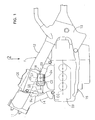
- Fig. 1 is a side view of a principal portion of a motorcycle;
- Fig. 2 is a plan view, viewed from the direction of an arrow 2 in Fig. 1 in a state in which an air cleaner is omitted;
- Fig. 3 is a front view of an intake air control device viewed from the direction of an arrow 3 in Fig. 2;
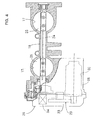
- Fig. 4 is a cross-sectional view taken along the line 4-4 in Fig. 3;
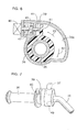
- Fig. 5 is a vertical cross-sectional view of a steering handle in the vicinity of a throttle grip;
- Fig. 6 is a cross-sectional view taken along the line 6-6 in Fig. 5;
- Fig. 7 is a perspective view viewed from the front in the vicinity of the throttle grip; and
- Fig. 8 is a block diagram showing a throttle control system.
- a vehicle body frame F of a motorcycle as a saddle type vehicle includes a head pipe 11 at a front end thereof, a pair of left and right main frames 12... bifurcated from the head pipe 11 to the left and right and obliquely extending rearward and downward, pivot plates 13... connected to rear portions of the both main frames 12..., and down pipes 14... bifurcated to the left and right under the both main frames 12..., connected to the head pipe 11 and obliquely extending rearward and downward at an angle steeper than the both main frames 12....
- An engine body 15 configured as a horizontally opposing type having six cylinders including three cylinders each extending in the fore-and-aft direction of the motorcycle arranged on both left and right sides is mounted to the vehicle body frame F so as to be positioned downwardly of the both main frames 12..., and the engine body 15 is supported by a midsection of the main frames 12..., the pivot plates 13... and the down pipes 14....
- An air cleaner 16 is mounted to the vehicle body frame F at a position above the engine body 15, and an air intake path forming body 18 which forms a pair of air intake paths 17, 17 arranged on the left and right direction of the vehicle body frame F is arranged between the air cleaner 16 and the engine body 15.
- An upper portion of the air intake path forming body 18 is connected to a lower portion of the air cleaner 16 so that upstream ends of the both air intake paths 17... communicate with the interior of a purification chamber (not shown) in the air cleaner 16.
- An intake manifold 22A having three intake pipes 19A, 20A, 21A which commonly communicate with one of downstream ends of the both air intake paths 17...
- an intake manifold 22B having three intake pipes 19B, 20B, 21B which commonly communicate with the other downstream end of the both air intake paths 17... are connected to a lower portion of the air intake path forming body 18, and the respective intake pipes 19A to 21A, 19B to 21B provided by the intake manifolds 22A, 22B are connected to left and right cylinder heads 23... provided by the engine body 15.
- a valve shaft 24 extending in the left and right direction of the vehicle body frame F across the both air intake paths 17, 17 is rotatably supported by the air intake path forming body 18, and butterfly-shaped throttle valves 25, 25 for controlling the opening of the both air intake paths 17... are fixed to the valve shaft 24.
- an actuator 26 for driving to rotate the valve shaft 24 is connected to an end of the valve shaft 24.
- the actuator 26 includes a valve shaft driving electric motor 28 having an axial line of rotation extending in parallel with an axial line of the valve shaft 24 and a decelerating gear mechanism 29 for decelerating the rotational power of the valve shaft driving electric motor 28 and transmitting the same to an end of the valve shaft 24, and the valve shaft driving electric motor 28 is stored and supported in a storage recess 30 provided in the air intake path forming body 18 in parallel with the axial line of the valve shaft 24.
- the air intake path forming body 18 is provided with a cover 33 for covering the actuator 26 mounted thereon and a throttle opening sensor 34 is stored in the cover 33 so that the throttle opening sensor 34 for detecting the opening of the throttle valves 25... that is, the rotational position of the valve shaft 24 is connected to an end of the valve shaft 24.
- the valve shaft driving electric motor 28 is arranged between the both main frames 12... in the vehicle body frame F in top view obtained by viewing the motorcycle from above as clearly shown in Fig. 2, and is arranged forwardly of the valve shaft 24 along the fore-and-aft direction of the motorcycle.
- the engine body 15 is mounted to the vehicle body frame F in a state in which a crank axial line CC extends along the fore-and-aft direction of the motorcycle.
- An axial line C1 of the valve shaft 24 and an axial line of rotation C2 of the valve shaft driving electric motor 28 are arranged on an imaginary line SL arranged above the engine body 15 in substantially parallel with the crank axial line CC in side view obtained by viewing the motorcycle from the side.
- a bar-shaped steering handle 35 is steerably supported by the head pipe 11 at the front end of the vehicle body frame F, and a throttle grip 36 is mounted to a right end portion of the steering handle 35 so as to enable a rider to grip and rotate.
- a grip driving electric motor 37 which is moved by the amount of rotation of the valve shaft 24, that is, according to a detected value of the throttle opening sensor 34, is disposed on the steering handle 35, and is interlocked and connected to the throttle grip 36.
- the grip driving electric motor 37 is mounted to the steering handle 35 by a mounting member 38 so as to have an axial line of rotation in parallel with an axial line of rotation of the throttle grip 36.
- a rotating frame 39 as a rotating member is mounted to the steering handle 35 so as to cover an inner end portion of the throttle grip 36, and be capable of rotating about the identical axial line to the throttle grip 36, so that the rotational power of the grip driving electric motor 37 is transmitted to the rotating frame 39 via a transmission gear mechanism 40.
- the grip driving electric motor 37 is interlocked and connected to the rotating frame 39.
- a return spring 48 (see Fig. 5) which urges the throttle grip 36 in the throttle closing direction indicated by an arrow 43 in Fig. 6 is provided between the throttle grip 36 and the steering handle 35.
- the throttle grip 36 is integrally provided with an arm portion 41 projecting in the radially outward direction within the rotating frame 39, and a pressing piece 44 which can rotate the throttle grip 36 in the throttle opening direction indicated by an arrow 42 in Fig. 6 by coming into abutment with the arm portion 41 is movable mounted to the rotating frame 39.
- a lost motion spring 45 whose spring load is set to a value larger than that of the return spring 48 is provided between the rotating frame 39 and the pressing piece 44 in a contracted state.
- a recess 39a for allowing the rotational movement of the arm portion 41 away from the pressing piece 44 when the throttle grip 36 in a state in which the arm portion 41 is in abutment with the pressing piece 44 is rotated in the throttle opening direction 42 is provided on an inner surface of the rotating frame 39.
- a cancel switch 46 for detecting that the throttle grip 36 is rotated in the throttle closing direction 43 with respect to the rotating frame 39 is mounted to the rotating frame 39.
- the cancel switch 46 is provided with a detection shaft 47 opposing the pressing piece 44 from the opposite side from the arm portion 41 of the throttle grip 36. In this manner, when the throttle grip 36 rotates toward the side of pressing the pressing piece 44 by the arm portion 41 and compressing the lost motion 45 that is, in the throttle closing direction 43, with respect to the rotating frame 39, the pressing piece 44 comes into abutment with the detection shaft 47 and the cancel switch 46 changes the switching mode.
- the amount of rotation of the throttle grip 36 is detected by a throttle operating amount sensor 49, and the throttle operating amount sensor 49 is mounted to the steering handle 35 together with the grip driving electric motor 37 with the mounting member 38.
- the throttle operating amount sensor 49 and the inner end of the throttle grip 36 are connected, for example by a gear-type interlocking/connecting mechanism 50.
- the movement of the valve shaft driving electric motor 28 in the actuator 26 is controlled by a control unit 52, and a signal from the throttle opening sensor 34, the throttle operating amount sensor 49, the cancel switch 46, a vehicle speed sensor 53, an intake air pressure sensor 54, an intake air temperature sensor 55, and an automatic cruise selection switch 56 for switching the motorcycle between the automatic cruising state and the non automatic cruising state are supplied to the control unit 52.
- the control unit 52 controls the movement of the valve shaft driving electric motor 28 so as to achieve the throttle opening according to the operating amount of the throttle.
- the control unit 52 controls the movement of the valve shaft driving electric motor 28 so as to control the throttle opening while considering the intake air pressure and the intake air temperature so as to maintain the vehicle speed obtained by the vehicle speed sensor 53 when the automatic cruise selection switch 56 is switched.
- the vehicle body frame F includes the head pipe 11 at the front end thereof and the pair of main frames 12... bifurcated from the head pipe 11 to the left and right and extending rearward, the actuator 26 including the valve shaft driving electric motor 28 which can demonstrate the power to rotate the valve shaft 24 is connected to the end of the valve shaft 24 extending in the left and right direction of the vehicle body frame F and rotatably supported by the air intake path forming body 18, and the valve shaft driving electric motor 28 having the axial line of rotation C2 which extends in parallel with the axial line C1 of the valve shaft 24 is arranged between the both main frames 12... in top view obtained by viewing the motorcycle from above. Therefore, the valve shaft driving electric motor 28 which constitutes a part of the actuator 26 can be protected by surrounding the pair of left and right main frames 12....
- valve shaft driving electric motor 28 arranged forwardly of the valve shaft 24 along the fore-and-aft direction of the motorcycle, the valve shaft driving electric motor 28 is effectively cooled by traveling wind of the motorcycle, and generation of a performance deterioration phenomenon resulted from heat can be prevented so that the operability of the valve shaft driving electric motor 28 can be increased.
- the engine body 15 configured into a horizontal opposed type is mounted to the vehicle body frame F in a posture with the crank axial line CC extending along the fore-and-aft direction of the motorcycle, and the axial line C1 of the valve shaft 24 and the axial line of rotation C2 of the valve shaft driving electric motor 28 are arranged on the imaginary line SL arranged above the engine body 15 in substantially parallel to the crank axial line CC in side view obtained by viewing the motorcycle from the side. Therefore, the intake air control device can be arranged in the vicinity of an upper surface of the engine body 15, and hence an air intake system can be downsized.
- the grip driving electric motor 37 which is moved by the amount of movement according to the amount of rotation of the valve shaft 24 in association with the movement of the actuator 26 is disposed on the steering handle 35 and is interlocked and connected to the throttle grip 36, when feeding back the rotational movement of the valve shaft 24 driven by the valve shaft driving electric motor 28 to the throttle grip 36, the cable is not necessary and hence laying of the cable is not necessary.
- the control unit 52 controls the movement of the valve shaft driving electric motor 28 so as to maintain the vehicle speed at a constant value. Therefore, by selecting the automatic cruising state by the automatic cruise selection switch 56, the motorcycle can be traveled at a constant vehicle speed and, in addition, the loading state of an internal combustion engine during the automatic cruising can be recognized by the rotation of the throttle grip 36, whereby a desirable feeling of travel can be obtained.
- the rotating frame 39 which rotates about the identical axial line to the throttle grip 36 by the transmission of the power from the grip driving electric motor 37 is mounted to the steering handle 35 so as to cause the throttle grip 36 to follow the rotation of the rotating frame 39
- the cancel switch 46 for detecting that the throttle grip 36 is rotated in the throttle closing direction 43 with respect to the rotating frame 39 is mounted to the rotating frame 39
- the control unit 52 releases the automatic cruising state in response to detection of relative rotation of the throttle grip 36 in the throttle closing direction 43 in the automatic cruising state. Therefore the rotation of the throttle grip 36 for releasing the automatic cruising state can be detected by the cancel switch 46 in good response in the structure without the interposition of the cable or the like.
- the present invention can be implemented widely not only in the motorcycles, but also in the saddle type vehicles.
- Object In a saddle type vehicle in which a valve shaft to which a throttle valve is secured is rotatably supported on an air intake path forming body, and an actuator having a valve shaft driving electric motor which is moved in response to the turning operation of a throttle grip is connected to an end of the valve shaft, so that the rotational movement of the valve shaft is fed back to the throttle grip, laying of a cable is not necessary, and the rotational movement of the valve shaft driven by the valve shaft driving electric motor can be fed back to the throttle grip.
- Solving Means A grip driving electric motor 37 which is moved by the amount of movement according to the amount of rotation of the valve shaft in response to the operation of the actuator is disposed on the steering handle 35, and is interlocked and connected to the throttle grip 36.
Landscapes
- Engineering & Computer Science (AREA)
- Mechanical Engineering (AREA)
- Chemical & Material Sciences (AREA)
- Combustion & Propulsion (AREA)
- General Engineering & Computer Science (AREA)
- Control Of Throttle Valves Provided In The Intake System Or In The Exhaust System (AREA)
- Control Of Driving Devices And Active Controlling Of Vehicle (AREA)
- Controls For Constant Speed Travelling (AREA)
- Control Of Vehicle Engines Or Engines For Specific Uses (AREA)
- Steering Devices For Bicycles And Motorcycles (AREA)
Applications Claiming Priority (1)
| Application Number | Priority Date | Filing Date | Title |
|---|---|---|---|
| JP2005303314A JP4414389B2 (ja) | 2005-10-18 | 2005-10-18 | 鞍乗り型車両 |
Publications (3)
| Publication Number | Publication Date |
|---|---|
| EP1777150A2 true EP1777150A2 (de) | 2007-04-25 |
| EP1777150A3 EP1777150A3 (de) | 2009-03-18 |
| EP1777150B1 EP1777150B1 (de) | 2010-07-07 |
Family
ID=37533225
Family Applications (1)
| Application Number | Title | Priority Date | Filing Date |
|---|---|---|---|
| EP06018696A Ceased EP1777150B1 (de) | 2005-10-18 | 2006-09-06 | Fahrzeug mit Sattel |
Country Status (4)
| Country | Link |
|---|---|
| US (1) | US7445071B2 (de) |
| EP (1) | EP1777150B1 (de) |
| JP (1) | JP4414389B2 (de) |
| DE (1) | DE602006015267D1 (de) |
Cited By (4)
| Publication number | Priority date | Publication date | Assignee | Title |
|---|---|---|---|---|
| WO2009124907A1 (en) * | 2008-04-10 | 2009-10-15 | Domino S.P.A. | Improved electronic throttle control device for motorcycles, snowmobiles and similar vehicles |
| WO2009156268A1 (de) * | 2008-06-24 | 2009-12-30 | Mahle International Gmbh | Aktuator |
| EP2075152A3 (de) * | 2007-12-26 | 2010-01-13 | Yamaha Hatsudoki Kabushiki Kaisha | Steuervorrichtung für Grätschsitz-Fahrzeug und Grätschsitz-Fahrzeug |
| WO2011121047A1 (de) * | 2010-04-01 | 2011-10-06 | Gustav Magenwirth Gmbh & Co Kg | Gasdrehgriff |
Families Citing this family (27)
| Publication number | Priority date | Publication date | Assignee | Title |
|---|---|---|---|---|
| DE102004033487B4 (de) * | 2004-07-10 | 2006-03-16 | Bayerische Motoren Werke Ag | Vorrichtung zur Erzeugung eines haptischen Signals bei einem Fahrzeug |
| JP4745258B2 (ja) * | 2007-01-29 | 2011-08-10 | 川崎重工業株式会社 | 電子制御スロットル装置及び自動二輪車 |
| US8640566B2 (en) | 2007-07-03 | 2014-02-04 | Honda Motor Co., Ltd. | Throttle device for vehicle |
| JP4777943B2 (ja) * | 2007-07-03 | 2011-09-21 | 本田技研工業株式会社 | 車両のスロットル装置 |
| JP4777944B2 (ja) * | 2007-07-03 | 2011-09-21 | 本田技研工業株式会社 | 車両のスロットル装置 |
| JP2009236004A (ja) * | 2008-03-27 | 2009-10-15 | Yamaha Motor Co Ltd | 自動二輪車 |
| US8482801B2 (en) * | 2008-04-10 | 2013-07-09 | Xerox Corporation | Storage of stamp information for error diffusion |
| JP5064342B2 (ja) * | 2008-09-19 | 2012-10-31 | 本田技研工業株式会社 | 鞍乗り型車両のスロットル開度検出装置 |
| US20100204874A1 (en) * | 2009-02-12 | 2010-08-12 | Michael William Oyer | Universal Motorcycle Cruise Control System |
| JP2010247681A (ja) * | 2009-04-16 | 2010-11-04 | Suzuki Motor Corp | 車両制御装置 |
| US8540281B2 (en) * | 2010-05-07 | 2013-09-24 | Tk Holdings Inc. | Steering system |
| CA2801334C (en) | 2010-06-03 | 2020-03-10 | Polaris Industries Inc. | Electronic throttle control |
| JP2013063760A (ja) * | 2011-08-31 | 2013-04-11 | Nippon Seiki Co Ltd | アクセルグリップ装置 |
| US8887594B2 (en) | 2012-02-17 | 2014-11-18 | Aks Engineering, Llc | Assembly for selectively locking the angular position of a biased throttle grip |
| JP2014025348A (ja) | 2012-07-24 | 2014-02-06 | Yamaha Motor Co Ltd | 鞍乗型車両 |
| US9205717B2 (en) | 2012-11-07 | 2015-12-08 | Polaris Industries Inc. | Vehicle having suspension with continuous damping control |
| JP5856215B2 (ja) * | 2014-04-02 | 2016-02-09 | 本田技研工業株式会社 | 鞍乗型車両 |
| JP5869611B2 (ja) * | 2014-04-02 | 2016-02-24 | 本田技研工業株式会社 | 鞍乗型車両 |
| WO2015186213A1 (ja) * | 2014-06-04 | 2015-12-10 | 株式会社エフ・シ-・シ- | 鞍乗り型車両 |
| CN107406094B (zh) | 2014-10-31 | 2020-04-14 | 北极星工业有限公司 | 用于控制车辆的系统和方法 |
| CA3043481C (en) | 2016-11-18 | 2022-07-26 | Polaris Industries Inc. | Vehicle having adjustable suspension |
| US10406884B2 (en) | 2017-06-09 | 2019-09-10 | Polaris Industries Inc. | Adjustable vehicle suspension system |
| US10987987B2 (en) | 2018-11-21 | 2021-04-27 | Polaris Industries Inc. | Vehicle having adjustable compression and rebound damping |
| US12397878B2 (en) | 2020-05-20 | 2025-08-26 | Polaris Industries Inc. | Systems and methods of adjustable suspensions for off-road recreational vehicles |
| MX2022015902A (es) | 2020-07-17 | 2023-01-24 | Polaris Inc | Suspensiones ajustables y operacion de vehiculo para vehiculos recreativos todoterreno. |
| JP7733506B2 (ja) | 2021-08-24 | 2025-09-03 | 東洋電装株式会社 | アクセルポジションセンサユニットおよびスロットルグリップ装置 |
| USD1060430S1 (en) * | 2022-02-28 | 2025-02-04 | Lekkie Limited | Throttle |
Family Cites Families (13)
| Publication number | Priority date | Publication date | Assignee | Title |
|---|---|---|---|---|
| US3982446A (en) * | 1975-05-30 | 1976-09-28 | Andrew Van Dyken | Cruise control apparatus for hand grip throttle control |
| JPS6050035A (ja) * | 1983-08-31 | 1985-03-19 | Yamaha Motor Co Ltd | 自動二輪車の自動調速装置 |
| US4848502A (en) * | 1986-12-05 | 1989-07-18 | Honda Giken Kogyo Kabushiki Kaisha | Constant vehicle speed retaining device for motorcycle |
| US4969531A (en) * | 1988-04-20 | 1990-11-13 | Honda Giken Kogyo Kabushiki Kaisha | Constant vehicle speed operation control method and device |
| US5893295A (en) * | 1997-07-24 | 1999-04-13 | Bronnert; Hervex. | Motorcycle cruise control |
| WO1999020482A1 (en) * | 1997-10-22 | 1999-04-29 | G-Zero Technologies, Llc | Motorcycle cruise control |
| US6250173B1 (en) * | 1998-12-21 | 2001-06-26 | Fred M. Huston | Cruise control for a motorcycle |
| JP4218817B2 (ja) * | 2000-03-03 | 2009-02-04 | 本田技研工業株式会社 | 自動二輪車の定車速保持装置 |
| US6820710B2 (en) * | 2001-09-12 | 2004-11-23 | Bryan W. Fechner | Motorcycle cruise control system with brake release |
| US6978694B2 (en) * | 2002-12-06 | 2005-12-27 | Magneti Marelli Powertrain U.S.A., Inc. | Handlebar throttle controller with hysteresis |
| JP4287291B2 (ja) * | 2004-01-06 | 2009-07-01 | ヤマハ発動機株式会社 | 車両のスロットル装置 |
| JP4537933B2 (ja) * | 2005-10-18 | 2010-09-08 | 本田技研工業株式会社 | 吸気制御装置 |
| US7315779B1 (en) * | 2006-12-22 | 2008-01-01 | Bombardier Recreational Products Inc. | Vehicle speed limiter |
-
2005
- 2005-10-18 JP JP2005303314A patent/JP4414389B2/ja not_active Expired - Fee Related
-
2006
- 2006-09-06 DE DE602006015267T patent/DE602006015267D1/de active Active
- 2006-09-06 EP EP06018696A patent/EP1777150B1/de not_active Ceased
- 2006-10-16 US US11/581,764 patent/US7445071B2/en active Active
Cited By (7)
| Publication number | Priority date | Publication date | Assignee | Title |
|---|---|---|---|---|
| EP2075152A3 (de) * | 2007-12-26 | 2010-01-13 | Yamaha Hatsudoki Kabushiki Kaisha | Steuervorrichtung für Grätschsitz-Fahrzeug und Grätschsitz-Fahrzeug |
| WO2009124907A1 (en) * | 2008-04-10 | 2009-10-15 | Domino S.P.A. | Improved electronic throttle control device for motorcycles, snowmobiles and similar vehicles |
| WO2009156268A1 (de) * | 2008-06-24 | 2009-12-30 | Mahle International Gmbh | Aktuator |
| CN102066723A (zh) * | 2008-06-24 | 2011-05-18 | 马勒国际有限公司 | 致动器 |
| US8450896B2 (en) | 2008-06-24 | 2013-05-28 | Mahle International Gmbh | Actuator |
| CN102066723B (zh) * | 2008-06-24 | 2013-10-02 | 马勒国际有限公司 | 致动器 |
| WO2011121047A1 (de) * | 2010-04-01 | 2011-10-06 | Gustav Magenwirth Gmbh & Co Kg | Gasdrehgriff |
Also Published As
| Publication number | Publication date |
|---|---|
| US7445071B2 (en) | 2008-11-04 |
| DE602006015267D1 (de) | 2010-08-19 |
| EP1777150A3 (de) | 2009-03-18 |
| EP1777150B1 (de) | 2010-07-07 |
| JP4414389B2 (ja) | 2010-02-10 |
| US20070084658A1 (en) | 2007-04-19 |
| JP2007113418A (ja) | 2007-05-10 |
Similar Documents
| Publication | Publication Date | Title |
|---|---|---|
| EP1777150B1 (de) | Fahrzeug mit Sattel | |
| EP1777396B1 (de) | Ansaugluftsteuervorrichtung | |
| US7311082B2 (en) | Straddle type vehicle having an electronic throttle valve system | |
| US7533653B2 (en) | Intake air control system for a V-type internal combustion engine and engine incorporating same | |
| US20080178840A1 (en) | Electronic control throttle system for a vehicle and vehicle equipped therewith | |
| JP4671356B2 (ja) | 鞍乗型車両 | |
| EP1777395B1 (de) | Ansaugluftsteuervorrichtung | |
| US8151766B2 (en) | Combustion engine and vehicle equipped with such engine | |
| JP6913465B2 (ja) | 内燃機関の制御装置 | |
| US8087505B2 (en) | Power unit for vehicle and vehicle equipped with the same | |
| JP5117212B2 (ja) | 自動二輪車のエンジン制御装置 | |
| JP2009197816A (ja) | エンジン | |
| JP2013204512A (ja) | エンジンのスロットル装置 | |
| JP2007064061A (ja) | 吸気装置及び自動二輪車 | |
| JP5129773B2 (ja) | 車両用エンジンの吸気制御装置 | |
| JP2012180762A (ja) | スロットル制御装置 | |
| JP4815252B2 (ja) | 定車速制御装置 | |
| JP4916562B2 (ja) | 自動二輪車のエンジンのスロットル制御装置 | |
| JP4916529B2 (ja) | エンジン | |
| JP2010127199A (ja) | スロットル装置 | |
| JP2009197814A (ja) | エンジン | |
| JP5672151B2 (ja) | 自動二輪車の吸気構造 | |
| JP2008202514A (ja) | スロットル開度検出装置及びこれを備えた車両 |
Legal Events
| Date | Code | Title | Description |
|---|---|---|---|
| PUAI | Public reference made under article 153(3) epc to a published international application that has entered the european phase |
Free format text: ORIGINAL CODE: 0009012 |
|
| 17P | Request for examination filed |
Effective date: 20060913 |
|
| AK | Designated contracting states |
Kind code of ref document: A2 Designated state(s): AT BE BG CH CY CZ DE DK EE ES FI FR GB GR HU IE IS IT LI LT LU LV MC NL PL PT RO SE SI SK TR |
|
| AX | Request for extension of the european patent |
Extension state: AL BA HR MK YU |
|
| PUAL | Search report despatched |
Free format text: ORIGINAL CODE: 0009013 |
|
| AK | Designated contracting states |
Kind code of ref document: A3 Designated state(s): AT BE BG CH CY CZ DE DK EE ES FI FR GB GR HU IE IS IT LI LT LU LV MC NL PL PT RO SE SI SK TR |
|
| AX | Request for extension of the european patent |
Extension state: AL BA HR MK RS |
|
| RIC1 | Information provided on ipc code assigned before grant |
Ipc: F02D 9/10 20060101ALN20090210BHEP Ipc: F02D 11/10 20060101ALI20090210BHEP Ipc: B62K 23/04 20060101AFI20090210BHEP |
|
| GRAP | Despatch of communication of intention to grant a patent |
Free format text: ORIGINAL CODE: EPIDOSNIGR1 |
|
| RAP1 | Party data changed (applicant data changed or rights of an application transferred) |
Owner name: HONDA MOTOR CO., LTD. |
|
| GRAS | Grant fee paid |
Free format text: ORIGINAL CODE: EPIDOSNIGR3 |
|
| AKX | Designation fees paid |
Designated state(s): DE GB IT |
|
| RIN1 | Information on inventor provided before grant (corrected) |
Inventor name: TAMURA, SEIZO Inventor name: YAMAZAKI, RYUTARO |
|
| GRAA | (expected) grant |
Free format text: ORIGINAL CODE: 0009210 |
|
| AK | Designated contracting states |
Kind code of ref document: B1 Designated state(s): DE GB IT |
|
| REG | Reference to a national code |
Ref country code: GB Ref legal event code: FG4D |
|
| REF | Corresponds to: |
Ref document number: 602006015267 Country of ref document: DE Date of ref document: 20100819 Kind code of ref document: P |
|
| PLBE | No opposition filed within time limit |
Free format text: ORIGINAL CODE: 0009261 |
|
| STAA | Information on the status of an ep patent application or granted ep patent |
Free format text: STATUS: NO OPPOSITION FILED WITHIN TIME LIMIT |
|
| 26N | No opposition filed |
Effective date: 20110408 |
|
| REG | Reference to a national code |
Ref country code: DE Ref legal event code: R097 Ref document number: 602006015267 Country of ref document: DE Effective date: 20110408 |
|
| REG | Reference to a national code |
Ref country code: GB Ref legal event code: 746 Effective date: 20140506 |
|
| REG | Reference to a national code |
Ref country code: DE Ref legal event code: R084 Ref document number: 602006015267 Country of ref document: DE Effective date: 20140430 |
|
| PGFP | Annual fee paid to national office [announced via postgrant information from national office to epo] |
Ref country code: DE Payment date: 20180821 Year of fee payment: 13 Ref country code: IT Payment date: 20180919 Year of fee payment: 13 |
|
| PGFP | Annual fee paid to national office [announced via postgrant information from national office to epo] |
Ref country code: GB Payment date: 20180905 Year of fee payment: 13 |
|
| REG | Reference to a national code |
Ref country code: DE Ref legal event code: R119 Ref document number: 602006015267 Country of ref document: DE |
|
| PG25 | Lapsed in a contracting state [announced via postgrant information from national office to epo] |
Ref country code: DE Free format text: LAPSE BECAUSE OF NON-PAYMENT OF DUE FEES Effective date: 20200401 |
|
| PG25 | Lapsed in a contracting state [announced via postgrant information from national office to epo] |
Ref country code: IT Free format text: LAPSE BECAUSE OF NON-PAYMENT OF DUE FEES Effective date: 20190906 |
|
| GBPC | Gb: european patent ceased through non-payment of renewal fee |
Effective date: 20190906 |
|
| PG25 | Lapsed in a contracting state [announced via postgrant information from national office to epo] |
Ref country code: GB Free format text: LAPSE BECAUSE OF NON-PAYMENT OF DUE FEES Effective date: 20190906 |