EP1777367A1 - Fluidmotor mit rotierender Bewegung - Google Patents
Fluidmotor mit rotierender Bewegung Download PDFInfo
- Publication number
- EP1777367A1 EP1777367A1 EP05256509A EP05256509A EP1777367A1 EP 1777367 A1 EP1777367 A1 EP 1777367A1 EP 05256509 A EP05256509 A EP 05256509A EP 05256509 A EP05256509 A EP 05256509A EP 1777367 A1 EP1777367 A1 EP 1777367A1
- Authority
- EP
- European Patent Office
- Prior art keywords
- piston
- pistons
- rotor
- fluid motor
- casing
- Prior art date
- Legal status (The legal status is an assumption and is not a legal conclusion. Google has not performed a legal analysis and makes no representation as to the accuracy of the status listed.)
- Ceased
Links
Images


Classifications
-
- F—MECHANICAL ENGINEERING; LIGHTING; HEATING; WEAPONS; BLASTING
- F01—MACHINES OR ENGINES IN GENERAL; ENGINE PLANTS IN GENERAL; STEAM ENGINES
- F01B—MACHINES OR ENGINES, IN GENERAL OR OF POSITIVE-DISPLACEMENT TYPE, e.g. STEAM ENGINES
- F01B5/00—Reciprocating-piston machines or engines with cylinder axes arranged substantially tangentially to a circle centred on main shaft axis
- F01B5/006—Reciprocating-piston machines or engines with cylinder axes arranged substantially tangentially to a circle centred on main shaft axis the connection of the pistons with an actuated or actuating element being at the inner ends of the cylinders
-
- F—MECHANICAL ENGINEERING; LIGHTING; HEATING; WEAPONS; BLASTING
- F01—MACHINES OR ENGINES IN GENERAL; ENGINE PLANTS IN GENERAL; STEAM ENGINES
- F01B—MACHINES OR ENGINES, IN GENERAL OR OF POSITIVE-DISPLACEMENT TYPE, e.g. STEAM ENGINES
- F01B13/00—Reciprocating-piston machines or engines with rotating cylinders in order to obtain the reciprocating-piston motion
- F01B13/04—Reciprocating-piston machines or engines with rotating cylinders in order to obtain the reciprocating-piston motion with more than one cylinder
- F01B13/045—Reciprocating-piston machines or engines with rotating cylinders in order to obtain the reciprocating-piston motion with more than one cylinder with cylinder axes arranged substantially tangentially to a circle centred on main shaft axis
-
- F—MECHANICAL ENGINEERING; LIGHTING; HEATING; WEAPONS; BLASTING
- F01—MACHINES OR ENGINES IN GENERAL; ENGINE PLANTS IN GENERAL; STEAM ENGINES
- F01B—MACHINES OR ENGINES, IN GENERAL OR OF POSITIVE-DISPLACEMENT TYPE, e.g. STEAM ENGINES
- F01B9/00—Reciprocating-piston machines or engines characterised by connections between pistons and main shafts, not specific to groups F01B1/00 - F01B7/00
- F01B9/04—Reciprocating-piston machines or engines characterised by connections between pistons and main shafts, not specific to groups F01B1/00 - F01B7/00 with rotary main shaft other than crankshaft
- F01B9/042—Reciprocating-piston machines or engines characterised by connections between pistons and main shafts, not specific to groups F01B1/00 - F01B7/00 with rotary main shaft other than crankshaft the connections comprising gear transmissions
- F01B2009/045—Planetary gearings
Definitions
- the present invention relates generally to fluid machinery and, more specifically, to a rotary fluid motor of the type including reciprocating pistons, which rotate around its axis of rotation.
- Patent No.: 3377968 (Japan) INTERNAL COMBUSTION ROTARY ENGINE
- a fluid motor has the same structure as that of the rotary internal combustion engine, including cylindrical casing, a rotor with an output shaft as its axis in the cylindrical casing and crankshafts, pistons, piston chambers within the rotor. Each piston chamber undergoes downward movement by pressured-fluid through inlet-port and is discharged through outlet-port.
- a fluid motor comprising: a casing defining a cylindrical chamber; a rotor with input shaft as the axis is in the said cylindrical chamber, crankshaft with pinion gear at the rear end in the rotor; piston chamber and piston in the rotor exists; drive train is provided to synchronize the rotation of the input shaft and the crankshaft.
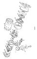
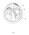
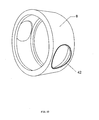
- the illustrated fluid motor comprises a casing formed of a pair of end plate 11, 13 and outer cylinder 15 securely assembled as shown to enclose a cylindrical rotor.
- Outlet-port 2 and inlet-port 1 extend through the outer cylinder 15 to provide communication with the piston chamber.
- the cylindrical rotor includes two annular bodies 8 having a cylindrical outer surface matching the cylindrical inner surface formed by outer cylinder 15 and has output shaft 3 as axis.
- the rotor includes front-mounting plate of crankshaft 9 (with it's cover), and rear-mounting plate of crankshaft 10 secured against the annular bodies 8.
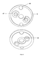
- crankshaft middle mounting plate that comprises output shaft arm mounting plate 43 and its cover 44 (detail of plate 43 and its cover 44 are shown in FIG.11).
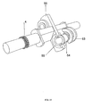
- the output shaft 3 is rotably mounted and extend through the casing by sleeve bearing mounted in the end plates 11, 13 of the casing.
- the axis of output shaft 3 and the axis of rotor are the same axis (or concentric) and rotate together.
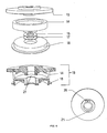
- crankshaft-mounting arm 56 is fixedly secured on the output shaft 3 for bodily rotation with it.
- a crankshaft-mounting arm 56 includes bearing housing 53, 55 and bearing 54.
- Piston chambers are fixedly secured with piston chamber bases 27 inside annular body of rotor 8. Each piston chamber axially extends to the outer surface of annular bodies of rotor 8, and wrapped by its cylindrical shape valve 7.
- seal 42 is inserted in rotor annular bodies 8 to protect lube oil leak from cylindrical shape valve 7.
- Axis of each piston chamber is preferably uniformly spaced from output shaft axis in the direction of rotor rotation.
- the cylindrical shape valve 7 is slightly movable along the axis of its piston chamber.
- the curved end of the valve is pressed with inner cylindrical surface of outer cylinder of casing 15 by coil springs 31 to fluid tight.
- the coil springs 31 is seated in spring stem 32 that mounted on piston chamber bases 27 and lower end of cylindrical shape valve 7 to prevent cylindrical valve from moving.
- At the outer surface of piston chamber base 27 has ring-seal 28 covered to prevent lube oil leak from cylindrical valve 7.
- Key 29 with spring is mounted in keyway 30, 34 on outside of each piston chamber and inside of its cylindrical shape valve 7 respectively.
- opening valve 35 and closing valve 36 are formed at the curve end of cylindrical shape valve 7, opening valve 35 to locate the start opening position of outlet-port and inlet-port, and closing valve 36 to locate the start closing position of outlet-port and inlet-port.
- a piston rod is pivotally connected to each piston 6 and rotatively connected to its corresponding crank of crankshaft 5 by bearing 54.
- the fluid motor has two motor blocks, the first and the second block, and each block has two pistons.
- the first motor block, piston chamber bases 27 are fixedly secured on crankshaft front mounting plate 9 and cover of output shaft arm mounting plate 44.
- the second motor block, piston chamber bases 27 are fixedly secured on crankshaft rear mounting plate 10 and output shaft arm mounting plate 43.
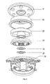
- FIG.4 between front end plate of casing 13 and crankshaft front mounting plate cover 9 is screw gear chamber 14, which enclose screw gear 4.
- the screw gear 4 is formed on the front end of output shaft 3 for driving lube oil pump.
- a drive train is provided to synchronize the rotation of the output shaft 3 and both of the crankshafts 5.
- the drive train includes an annular gear-carrying cap 22 in drive train chamber 12.
- the drive train chamber 12 is between rear end plate of casing 11 and crankshaft rear mounting plate 10.
- a sleeve carry the output shaft is formed at the center of annular gear-carrying cap 22 with one end of this sleeve fixedly secured to rear end plate of casing 11.
- An annular gear 23 is fixed to the annular gear-carrying cap 22.
- the annular gear 23 mesh with pinion gears formed on the rear end of both crankshafts 5.
- the drive train shall specify the gear teeth ratio of annular gear to pinion gear to be appropriate to rotary fluid motor efficiency preferably twice the number of pistons in each motor block.
- the gear teeth ration of annular gear to pinion gear shall be 4:1 so that when the output shaft rotates one round clockwise, the crankshafts will rotate four rounds.
- the gear teeth ration of 3, 4, 6, 8 pistons rotary pressurizing motor shall be 6:1, 8:1, 12:1 and 16:1 respectively.
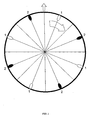
- operation sequence of the rotary pressurizing motor as shown in FIG. 15 and FIG. 16 illustrates two sets piston of motor block. Each block comprises two-pistons.
- piston chamber No. 1 & 2 passes through the inlet-port while the piston moves down by the pressured-fluid into its piston chamber.
- the piston complete it downward-stroke, the inlet-stroke is also complete.
- the second motor block is operated in outlet-stroke (Fig.15 position 60, 61, 62).
- Outlet-stroke of the first motor block occurs when piston chamber No. 1 & 2 continues moving around the output shaft while the crankshaft drives piston No. 1 & 2 move up to discharge fluid.
- the second motor block is operating in inlet-stroke (Fig.16 position 65, 66).
- Piston chamber No.1 and No.2 make the first motor block while piston chamber No.3 and No.4 make the second piston chamber set.
- the movement of each pair of piston must be balanced in order to maximize the output-power.
- the rotary pressurizing motor might comprise a plurality of motor block preferably.
- one motor block may comprise a plurality of pistons and piston chambers preferably at least two for the same requirement for balancing.
- the inlet stroke of each piston will substantially twice to no. of piston in each motor block that are six, eight, twelve and sixteen for 3, 4, 6, 8 pistons motor block.
Landscapes
- Engineering & Computer Science (AREA)
- Mechanical Engineering (AREA)
- General Engineering & Computer Science (AREA)
- Hydraulic Motors (AREA)
Priority Applications (1)
| Application Number | Priority Date | Filing Date | Title |
|---|---|---|---|
| EP05256509A EP1777367A1 (de) | 2005-10-20 | 2005-10-20 | Fluidmotor mit rotierender Bewegung |
Applications Claiming Priority (1)
| Application Number | Priority Date | Filing Date | Title |
|---|---|---|---|
| EP05256509A EP1777367A1 (de) | 2005-10-20 | 2005-10-20 | Fluidmotor mit rotierender Bewegung |
Publications (1)
| Publication Number | Publication Date |
|---|---|
| EP1777367A1 true EP1777367A1 (de) | 2007-04-25 |
Family
ID=37887861
Family Applications (1)
| Application Number | Title | Priority Date | Filing Date |
|---|---|---|---|
| EP05256509A Ceased EP1777367A1 (de) | 2005-10-20 | 2005-10-20 | Fluidmotor mit rotierender Bewegung |
Country Status (1)
| Country | Link |
|---|---|
| EP (1) | EP1777367A1 (de) |
Citations (4)
| Publication number | Priority date | Publication date | Assignee | Title |
|---|---|---|---|---|
| US4166438A (en) * | 1976-11-11 | 1979-09-04 | Gottschalk Eldon W | Machine with reciprocating pistons and rotating piston carrier |
| EP1085182A1 (de) * | 1999-09-14 | 2001-03-21 | Chanchai Santiyanont | Rotierende Brennkraftmaschine |
| US20020056420A1 (en) * | 1998-09-18 | 2002-05-16 | Chanchai Santiyanont | Internal combustion rotary engine |
| US20030154936A1 (en) * | 1998-09-18 | 2003-08-21 | Chanchai Santiyanont | Rotary compressor or pump |
-
2005
- 2005-10-20 EP EP05256509A patent/EP1777367A1/de not_active Ceased
Patent Citations (4)
| Publication number | Priority date | Publication date | Assignee | Title |
|---|---|---|---|---|
| US4166438A (en) * | 1976-11-11 | 1979-09-04 | Gottschalk Eldon W | Machine with reciprocating pistons and rotating piston carrier |
| US20020056420A1 (en) * | 1998-09-18 | 2002-05-16 | Chanchai Santiyanont | Internal combustion rotary engine |
| US20030154936A1 (en) * | 1998-09-18 | 2003-08-21 | Chanchai Santiyanont | Rotary compressor or pump |
| EP1085182A1 (de) * | 1999-09-14 | 2001-03-21 | Chanchai Santiyanont | Rotierende Brennkraftmaschine |
Similar Documents
| Publication | Publication Date | Title |
|---|---|---|
| US7681549B2 (en) | Oscillating piston engine | |
| US5123394A (en) | Rotary reciprocating internal combustion engine | |
| US4421073A (en) | Rotating cylinder internal combustion engine | |
| KR100987914B1 (ko) | 왕복 및 회전식 내연기관, 압축기 및 펌프 | |
| US7721685B2 (en) | Rotary cylindrical power device | |
| US20060090638A1 (en) | Rotary fluid motor | |
| US6813989B2 (en) | Rotary compressor or pump | |
| US3964442A (en) | Internal combustion engine | |
| US6536383B2 (en) | Internal combustion rotary engine | |
| US20070062469A1 (en) | Rotary radial internal combustion piston engine | |
| WO1989006303A1 (en) | Pump or motor with at least one piston body provided in a cylindrical housing | |
| EP1777367A1 (de) | Fluidmotor mit rotierender Bewegung | |
| WO2008122126A1 (en) | Rotary engine | |
| JP4521785B1 (ja) | 回転ピストン機械 | |
| EP1085182B1 (de) | Rotierende Brennkraftmaschine | |
| RU2271451C2 (ru) | Роторная машина | |
| RU2030640C1 (ru) | Объемная машина | |
| RU2194164C1 (ru) | Роторная объемная машина | |
| US8684714B2 (en) | Internal orbital engine | |
| KR100372164B1 (ko) | 동축 왕복형 2행정엔진 | |
| RO129579B1 (ro) | Motor rotativ cu ardere internă în patru timpi | |
| GB2094403A (en) | Rotary positive-displacement fluid-machines | |
| MXPA05007956A (es) | Motor/bomba radial. | |
| GB2133474A (en) | A rotary internal-combustion engine | |
| IL169917A (en) | Rotary radial internal combustion piston engine |
Legal Events
| Date | Code | Title | Description |
|---|---|---|---|
| PUAI | Public reference made under article 153(3) epc to a published international application that has entered the european phase |
Free format text: ORIGINAL CODE: 0009012 |
|
| AK | Designated contracting states |
Kind code of ref document: A1 Designated state(s): AT BE BG CH CY CZ DE DK EE ES FI FR GB GR HU IE IS IT LI LT LU LV MC NL PL PT RO SE SI SK TR |
|
| AX | Request for extension of the european patent |
Extension state: AL BA HR MK YU |
|
| 17P | Request for examination filed |
Effective date: 20070813 |
|
| 17Q | First examination report despatched |
Effective date: 20071015 |
|
| AKX | Designation fees paid |
Designated state(s): AT BE BG CH CY CZ DE DK EE ES FI FR GB GR HU IE IS IT LI LT LU LV MC NL PL PT RO SE SI SK TR |
|
| AXX | Extension fees paid |
Extension state: YU Payment date: 20070813 Extension state: MK Payment date: 20070813 Extension state: HR Payment date: 20070813 Extension state: BA Payment date: 20070813 Extension state: AL Payment date: 20070813 |
|
| STAA | Information on the status of an ep patent application or granted ep patent |
Free format text: STATUS: THE APPLICATION HAS BEEN REFUSED |
|
| 18R | Application refused |
Effective date: 20130214 |