EP1777450A2 - Überwurfmutter aus Kunststoff - Google Patents
Überwurfmutter aus Kunststoff Download PDFInfo
- Publication number
- EP1777450A2 EP1777450A2 EP06025290A EP06025290A EP1777450A2 EP 1777450 A2 EP1777450 A2 EP 1777450A2 EP 06025290 A EP06025290 A EP 06025290A EP 06025290 A EP06025290 A EP 06025290A EP 1777450 A2 EP1777450 A2 EP 1777450A2
- Authority
- EP
- European Patent Office
- Prior art keywords
- nut
- halves
- plastic
- component
- hook
- Prior art date
- Legal status (The legal status is an assumption and is not a legal conclusion. Google has not performed a legal analysis and makes no representation as to the accuracy of the status listed.)
- Withdrawn
Links
Images
Classifications
-
- F—MECHANICAL ENGINEERING; LIGHTING; HEATING; WEAPONS; BLASTING
- F16—ENGINEERING ELEMENTS AND UNITS; GENERAL MEASURES FOR PRODUCING AND MAINTAINING EFFECTIVE FUNCTIONING OF MACHINES OR INSTALLATIONS; THERMAL INSULATION IN GENERAL
- F16B—DEVICES FOR FASTENING OR SECURING CONSTRUCTIONAL ELEMENTS OR MACHINE PARTS TOGETHER, e.g. NAILS, BOLTS, CIRCLIPS, CLAMPS, CLIPS OR WEDGES; JOINTS OR JOINTING
- F16B37/00—Nuts or like thread-engaging members
- F16B37/08—Quickly-detachable or mountable nuts, e.g. consisting of two or more parts; Nuts movable along the bolt after tilting the nut
- F16B37/0871—Quickly-detachable or mountable nuts, e.g. consisting of two or more parts; Nuts movable along the bolt after tilting the nut engaging the bolt laterally, i.e. without the need to engage the end of the bolt
- F16B37/0885—Quickly-detachable or mountable nuts, e.g. consisting of two or more parts; Nuts movable along the bolt after tilting the nut engaging the bolt laterally, i.e. without the need to engage the end of the bolt in two halves hingedly connected
-
- B—PERFORMING OPERATIONS; TRANSPORTING
- B67—OPENING, CLOSING OR CLEANING BOTTLES, JARS OR SIMILAR CONTAINERS; LIQUID HANDLING
- B67D—DISPENSING, DELIVERING OR TRANSFERRING LIQUIDS, NOT OTHERWISE PROVIDED FOR
- B67D3/00—Apparatus or devices for controlling flow of liquids under gravity from storage containers for dispensing purposes
- B67D3/04—Liquid-dispensing taps or cocks adapted to seal and open tapping holes of casks, e.g. for beer
-
- F—MECHANICAL ENGINEERING; LIGHTING; HEATING; WEAPONS; BLASTING
- F16—ENGINEERING ELEMENTS AND UNITS; GENERAL MEASURES FOR PRODUCING AND MAINTAINING EFFECTIVE FUNCTIONING OF MACHINES OR INSTALLATIONS; THERMAL INSULATION IN GENERAL
- F16B—DEVICES FOR FASTENING OR SECURING CONSTRUCTIONAL ELEMENTS OR MACHINE PARTS TOGETHER, e.g. NAILS, BOLTS, CIRCLIPS, CLAMPS, CLIPS OR WEDGES; JOINTS OR JOINTING
- F16B37/00—Nuts or like thread-engaging members
- F16B37/08—Quickly-detachable or mountable nuts, e.g. consisting of two or more parts; Nuts movable along the bolt after tilting the nut
- F16B37/0871—Quickly-detachable or mountable nuts, e.g. consisting of two or more parts; Nuts movable along the bolt after tilting the nut engaging the bolt laterally, i.e. without the need to engage the end of the bolt
- F16B37/0892—Quickly-detachable or mountable nuts, e.g. consisting of two or more parts; Nuts movable along the bolt after tilting the nut engaging the bolt laterally, i.e. without the need to engage the end of the bolt in two or more pieces, e.g. assemblies made by two C-shaped nuts mutually interlocked, or retained by an additional member
-
- F—MECHANICAL ENGINEERING; LIGHTING; HEATING; WEAPONS; BLASTING
- F16—ENGINEERING ELEMENTS AND UNITS; GENERAL MEASURES FOR PRODUCING AND MAINTAINING EFFECTIVE FUNCTIONING OF MACHINES OR INSTALLATIONS; THERMAL INSULATION IN GENERAL
- F16L—PIPES; JOINTS OR FITTINGS FOR PIPES; SUPPORTS FOR PIPES, CABLES OR PROTECTIVE TUBING; MEANS FOR THERMAL INSULATION IN GENERAL
- F16L19/00—Joints in which sealing surfaces are pressed together by means of a member, e.g. a swivel nut, screwed on, or into, one of the joint parts
- F16L19/02—Pipe ends provided with collars or flanges, integral with the pipe or not, pressed together by a screwed member
- F16L19/0231—Pipe ends provided with collars or flanges, integral with the pipe or not, pressed together by a screwed member with specially adapted means for positioning the threaded member behind the collar
-
- B—PERFORMING OPERATIONS; TRANSPORTING
- B67—OPENING, CLOSING OR CLEANING BOTTLES, JARS OR SIMILAR CONTAINERS; LIQUID HANDLING
- B67D—DISPENSING, DELIVERING OR TRANSFERRING LIQUIDS, NOT OTHERWISE PROVIDED FOR
- B67D3/00—Apparatus or devices for controlling flow of liquids under gravity from storage containers for dispensing purposes
- B67D3/04—Liquid-dispensing taps or cocks adapted to seal and open tapping holes of casks, e.g. for beer
- B67D3/047—Liquid-dispensing taps or cocks adapted to seal and open tapping holes of casks, e.g. for beer with a closing element having a rotational movement
Definitions
- the invention relates to a union nut made of plastic, which is composed of two nut halves on a first component and held captive on this, wherein the nut halves an internally threaded segment and an inwardly directed annular shoulder segment for engaging a corresponding collar of the first with a second component to be screwed component have, in particular for screwing the fitting housing of a removal fitting on the provided with an external thread outlet nozzle of a transport and storage container made of plastic or metal for liquids and bulk material.
- the DE 43 22 032 C1 describes a cable gland for the sealed laying of pipes and conduits by device walls and the like components, which consists of a double nipple with end-side threaded connector and an interposed polygon approach for a tool, the nipple having at one end an internally circumferential stop collar on which a Seals supported by a pipe or a pipe is pushed through.
- the sealing body is biased by means of a screw-on the other end of the nipple nut with a stop collar.
- the sealing body, the sealing nipple and the union nut each consist of two halves, so that a damaged cable gland is easily replaceable.
- the two halves of the cap nut are held together by arranged at both ends of the nut halves snap hook elements.
- the invention has for its object to further develop the generic union nut with a view to a simplified assembly.
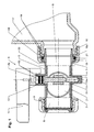
- the made of a high-density polyethylene (PE-HD) Hahn housing 2 of the flap valve 1 of FIG. 1 receives a disc 3 for opening and closing the central flow opening 4 of the housing chamber 5, with the inlet channel 6 of the inlet nozzle 7 and the outlet channel. 8 the outlet nozzle 9 of the valve body 2 is in communication.
- the disc 3 is mounted eccentrically on a rotary shaft 10, the two ends 10 a, 10 b are rotatably mounted in bearing stub 11, 12 of the valve housing 2, wherein the upper end 10 b of the rotary shaft 3 projects beyond the bearing neck 12 from the valve body 2 to the outside.
- the rotary shaft 10 is sealed by means of sealing rings 13 in the bearing neck 12 to the outside.
- a handle 14 for opening and closing the valve cock 1 is attached on the protruding from the cock housing 2 end 10 b of the rotary shaft 10 of the disc 3.
- the flap valve 1 is by means of a union nut 44 made of plastic attached to the outlet nozzle 16 of a liquid container 17, for example a plastic inner container of a pallet container, wherein the liquid container 17 is integrally formed with the male thread 18 provided with a spout 16 by blow molding.
- the union nut 44 is held between a collar 19 of the inlet nozzle 7 and the bearing stub 11, 12 of the valve housing 2 for the rotary shaft 10 of the disc 3 captive and slidable on the inlet nozzle of the valve housing 2.
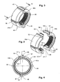
- the union nut 44 of Figures 2 to 4 consists of two manufactured as plastic injection molded nut halves 44a, 44b with an internal thread segment 50 and an inwardly directed annular shoulder segment 20a, 20b.
- the two nut halves 44a, 44b are connected to each other by means of a hook connection 45 and a clip connection 46.
- the first nut half 44a is provided with a hook-shaped end 47 for hooking into an insertion opening 48 of a recess 49 of the internal thread segment 50 in one end 51 of the second nut half 44b and to the other end 52 of the first nut half 44a is a latching tongue 53 is integrally formed with a locking edge 54 ,
- the union nut 44 is provided on the circumference with gripping ribs 96 as an assembly aid.
Landscapes
- Engineering & Computer Science (AREA)
- General Engineering & Computer Science (AREA)
- Mechanical Engineering (AREA)
- Clamps And Clips (AREA)
- Valve Housings (AREA)
- Details Of Rigid Or Semi-Rigid Containers (AREA)
- Mutual Connection Of Rods And Tubes (AREA)
- Connection Of Plates (AREA)
- Moulds For Moulding Plastics Or The Like (AREA)
- Injection Moulding Of Plastics Or The Like (AREA)
- Closures For Containers (AREA)
- Infusion, Injection, And Reservoir Apparatuses (AREA)
Abstract
Description
- Die Erfindung betrifft eine Überwurfmutter aus Kunststoff, die aus zwei Mutterhälften auf einem ersten Bauteil zusammengesetzt und auf diesem unverlierbar gehalten wird, wobei die Mutterhälften ein Innengewindesegment und ein nach innen gerichtetes Ringschultersegment zum Angreifen an einem entsprechenden Bund des ersten mit einem zweiten Bauteil zu verschraubenden Bauteils aufweisen, insbesondere zum Anschrauben des Armaturengehäuses einer Entnahmearmatur an dem mit einem Außengewinde versehenen Auslaufstutzen eines Transport- und Lagerbehälters aus Kunststoff oder Metall für Flüssigkeiten und Schüttgut.
- Aus der
DE 103 01 517 B3 ist ein Transport- und Lagerbehälter für Flüssigkeiten mit einem auf einem palettenartigen Untergestell stehenden Innenbehälter aus Kunststoff und einem äußeren Gitterkorb bekannt. Die Entnahmearmatur des Innenbehälters wird mittels einer unverlierbar auf dem Einlaufstutzen der Armatur angeordneten Überwurfmutter aus Kunststoff der gattungsgemäßen Art, die aus zwei Mutterhälften auf dem Einlaufstutzen zusammengeschweißt wird, an den Auslaufstutzen des Innenbehälters angeschraubt. Bei einer Herstellung der Überwurfmutter aus Aluminium werden die beiden Mutterhälften auf dem Einlaufstutzen der Entnahmearmatur zusammengenietet. Eine derartige unverlierbare Anbringung einer Überwurfmutter auf dem Einlaufstutzen einer Entnahmearmatur ist umständlich und zeitaufwendig und führt zu einer Verteuerung der Herstellungskosten. - Die
DE 43 22 032 C1 beschreibt eine Kabelverschraubung zum abgedichteten Verlegen von Rohren und Leitungen durch Gerätewände und dergleichen Bauteile, die aus einem Doppelnippel mit endseitigen Gewindestutzen und einem dazwischen angeordneten Polygonansatz für ein Werkzeug besteht, wobei der Nippel an seinem einen Ende einen innen umlaufenden Anschlagkragen aufweist, an welchem sich ein Dichtkörper abstützt, durch den ein Rohr oder eine Leitung durchgeschoben wird. Der Dichtkörper wird mittels einer auf das andere Ende des Nippels aufschraubbaren Überwurfmutter mit einem Anschlagkragen vorgespannt. Der Dichtkörper, der Dichtnippel und die Überwurfmutter bestehen jeweils aus zwei Hälften, so dass eine beschädigte Kabelverschraubung leicht auswechselbar ist. Die beiden Hälften der Überwurfmutter werden durch an beiden Enden der Mutterhälften angeordnete Rasthakenelemente zusammengehalten. - Der Erfindung liegt die Aufgabe zugrunde, die gattungsgemäße Überwurfmutter im Hinblick auf eine vereinfachte Montage weiterzuentwickeln.
- Diese Aufgabe wird erfindungsgemäß gelöst durch eine Überwurfmutter mit den Merkmalen des Patentanspruchs.
- Die erfindungsgemäße Überwurfmutter ist nachstehend anhand von Zeichnungsfiguren erläutert, die folgendes darstellen:
- Fig. 1
- eine Längsschnittdarstellung eines Klappenhahns, der mittels einer in den Figuren 2 bis 4 im einzelnen dargestellten Überwurfmutter an den Auslaufstutzen eines Flüssigkeitsbehälters angeschraubt ist, die
- Fign. 2 und 3
- perspektivische Darstellungen der getrennten sowie der zusammengesetzten Mutterhälften der zum Anschrauben des Klappenhahns nach Figur 1 verwendeten Überwurfmutter und
- Fig.4
- einen Schnitt nach Linie IV-IV der Figur 3.
- Das aus einem Polyethylen hoher Dichte (PE-HD) hergestellte Hahngehäuse 2 des Klappenhahns 1 nach Fig. 1 nimmt eine Klappenscheibe 3 zum Öffnen und Schließen der zentralen Durchflußöffnung 4 der Gehäusekammer 5 auf, die mit dem Einlaufkanal 6 des Einlaufstutzens 7 und dem Auslaufkanal 8 des Auslaufstutzens 9 des Hahngehäuses 2 in Verbindung steht. Die Klappenscheibe 3 ist exzentrisch an einer Drehwelle 10 befestigt, deren beide Enden 10a, 10b in Lagerstutzen 11, 12 des Hahngehäuses 2 drehbar gelagert sind, wobei das obere Ende 10b der Drehwelle 3 über den Lagerstutzen 12 aus dem Hahngehäuse 2 nach außen vorsteht. Die Drehwelle 10 ist mittels Dichtringen 13 in dem Lagerstutzen 12 nach außen abgedichtet. Auf dem aus dem Hahngehäuse 2 herausragenden Ende 10b der Drehwelle 10 der Klappenscheibe 3 ist ein Handgriff 14 zum Öffnen und Schließen des Klappenhahns 1 angebracht.
- Der Klappenhahn 1 ist mittels einer Überwurfmutter 44 aus Kunststoff an dem Auslaufstutzen 16 eines Flüssigkeitsbehälters 17, z.B. eines Kunststoff-Innenbehälters eines Palettenbehälters, befestigt, wobei der Flüssigkeitsbehälter 17 mit dem mit einem Außengewinde 18 versehenen Auslaufstutzen 16 einteilig durch Blasformen hergestellt ist.
- Die Überwurfmutter 44 ist zwischen einem Bund 19 des Einlaufstutzens 7 und den Lagerstutzen 11, 12 des Hahngehäuses 2 für die Drehwelle 10 der Klappenscheibe 3 unverlierbar und verschiebbar auf dem Einlaufstutzen des Hahngehäuses 2 gehalten.
- Beim Einziehen des Einlaufstutzens 7 des Hahngehäuses 2 in den Auslaufstutzen 16 des Flüssigkeitsbehälters 17 durch das Aufschrauben der auf dem Einlaufstutzen 7 des Hahngehäuses 2 unverlierbar gehaltenen Überwurfmutter 44, die mit einer Ringschulter 20 an dem Bund 19 des Einlaufstutzens 7 angreift, auf dem Auslaufstutzen 16 wird ein auf dem Einlaufstutzen 7 sitzender Dichtring 21 zwischen dem Bund 19 und dem äußeren Ende 16a des Auslaufstutzens 16 des Flüssigkeitsbehälters 17 eingespannt und dadurch das Gehäuse 2 des Klappenhahns 1 gegen den Flüssigkeitsbehälter 17 abgedichtet.
- Die Überwurfmutter 44 nach den Figuren 2 bis 4 besteht aus zwei als Kunststoff-Spritzgußteile hergestellten Mutterhälften 44a, 44b mit einem Innengewindesegment 50 und einem nach innen gerichteten Ringschultersegment 20a, 20b. Die beiden Mutterhälften 44a, 44b werden mittels einer Hakenverbindung 45 und einer Clipverbindung 46 miteinander verbunden. Die erste Mutterhälfte 44a ist mit einem hakenförmigen Ende 47 zum Einhaken in eine Durchstecköffnung 48 einer Aussparung 49 des Innengewindesegments 50 im einen Ende 51 der zweiten Mutterhälfte 44b versehen und an das andere Ende 52 der ersten Mutterhälfte 44a ist eine Rastzunge 53 mit einer Rastkante 54 angeformt. Beim Zusammensetzen der beiden Mutterhälften 44a, 44b untergreift die Rastzunge 53 einen an das andere Ende 55 der zweiten Mutterhälfte 44b angeformten, abgestuften Haltesteg 56 und verrastet mit der Rastkante 54 mit der Rückseite 57 des Haltesteges 56.
- Die Überwurfmutter 44 ist auf dem Umfang mit Greifrippen 96 als Montagehilfe versehen.
Claims (1)
- Überwurfmutter (44) aus Kunststoff, die aus zwei Mutterhälften (44a, 44b) auf einem ersten Bauteil zusammengesetzt und auf diesem unverlierbar gehalten wird, wobei die Mutterhälften (44a, 44b) ein Innengewindesegment (50) und ein nach innen gerichtetes Ringschultersegment (20a, 20b) zum Angreifen an einem entsprechenden Bund (19) des ersten mit einem zweiten Bauteil zu verschraubenden Bauteils aufweisen, insbesondere zum Anschrauben des Armaturengehäuses (2) einer Entnahmearmatur (1) an dem mit einem Außengewinde (18) versehenden Auslaufstutzen (16) eines Transport- und Lagerbehälters (17) aus Kunststoff oder Metall für Flüssigkeiten und Schüttgut, gekennzeichnet durch zwei mittels einer Hakenverbindung (45) und einer Clipverbindung (46) zusammensetzbare Mutterhälften (44a, 44b), wobei die erste Mutterhälfte (44a) ein hakenförmiges Ende (47) zum Einhaken in eine Durchstecköffnung (48) einer Aussparung (49) des Gewindesegments (50) in einem Ende (51) der zweiten Mutterhälfte (44b) aufweist und an das andere Ende (52) der ersten Mutterhälfte (44a) eine Rastzunge (53) mit einer Rastkante (54) angeformt ist, wobei beim Zusammensetzen der beiden Mutterhälften (44a, 44b) die Rastzunge (53) einen an das andere Ende (55) der zweiten Mutterhälfte (44b) angeformten Haltesteg (56) untergreift und mit der Rastkante (54) mit der Rückseite (57) des Haltesteges (56)verrastet.
Applications Claiming Priority (3)
| Application Number | Priority Date | Filing Date | Title |
|---|---|---|---|
| DE102004039481 | 2004-08-14 | ||
| DE102004058252A DE102004058252B4 (de) | 2004-08-14 | 2004-12-03 | Überwurfmutter aus Kunststoff |
| EP05017173A EP1626218A3 (de) | 2004-08-14 | 2005-08-06 | Überwurfmutter aus Kunststoff |
Related Parent Applications (1)
| Application Number | Title | Priority Date | Filing Date |
|---|---|---|---|
| EP05017173A Division EP1626218A3 (de) | 2004-08-14 | 2005-08-06 | Überwurfmutter aus Kunststoff |
Publications (2)
| Publication Number | Publication Date |
|---|---|
| EP1777450A2 true EP1777450A2 (de) | 2007-04-25 |
| EP1777450A3 EP1777450A3 (de) | 2008-03-12 |
Family
ID=35058604
Family Applications (3)
| Application Number | Title | Priority Date | Filing Date |
|---|---|---|---|
| EP06025290A Withdrawn EP1777450A3 (de) | 2004-08-14 | 2005-08-06 | Überwurfmutter aus Kunststoff |
| EP06025291A Expired - Lifetime EP1777451B1 (de) | 2004-08-14 | 2005-08-06 | Überwurfmutter aus Kunststoff |
| EP05017173A Ceased EP1626218A3 (de) | 2004-08-14 | 2005-08-06 | Überwurfmutter aus Kunststoff |
Family Applications After (2)
| Application Number | Title | Priority Date | Filing Date |
|---|---|---|---|
| EP06025291A Expired - Lifetime EP1777451B1 (de) | 2004-08-14 | 2005-08-06 | Überwurfmutter aus Kunststoff |
| EP05017173A Ceased EP1626218A3 (de) | 2004-08-14 | 2005-08-06 | Überwurfmutter aus Kunststoff |
Country Status (16)
| Country | Link |
|---|---|
| US (1) | US7735667B2 (de) |
| EP (3) | EP1777450A3 (de) |
| JP (1) | JP2006052854A (de) |
| CN (1) | CN100439726C (de) |
| AR (1) | AR050371A1 (de) |
| AT (1) | ATE413559T1 (de) |
| AU (1) | AU2005203612B2 (de) |
| BR (1) | BRPI0503386A (de) |
| DE (2) | DE102004058252B4 (de) |
| DK (1) | DK1777451T3 (de) |
| ES (1) | ES2315986T3 (de) |
| MX (1) | MXPA05008458A (de) |
| MY (1) | MY153181A (de) |
| NO (1) | NO20053491L (de) |
| PL (1) | PL1777451T3 (de) |
| RU (1) | RU2300025C2 (de) |
Cited By (1)
| Publication number | Priority date | Publication date | Assignee | Title |
|---|---|---|---|---|
| CN112013002A (zh) * | 2020-07-23 | 2020-12-01 | 天台天宇光电股份有限公司 | 一种双半边螺帽 |
Families Citing this family (47)
| Publication number | Priority date | Publication date | Assignee | Title |
|---|---|---|---|---|
| US8221043B2 (en) * | 2008-02-18 | 2012-07-17 | Lockheed Martin Corporation | Releasable fastener systems and methods |
| US8142127B1 (en) * | 2008-10-28 | 2012-03-27 | United States Of America As Represented By The Secretary Of The Navy | Torque nut assembly |
| DE102009010651A1 (de) * | 2009-02-26 | 2010-09-02 | Contech3 Gmbh | Gegenmutter |
| US20100219185A1 (en) * | 2009-02-27 | 2010-09-02 | Griffin Ronald H | Sealing System For Pressure Vessels |
| US20100310211A1 (en) * | 2009-04-16 | 2010-12-09 | Babin Robin Mark | Systems and methods for installation of devices around an element |
| US10086984B2 (en) * | 2009-06-30 | 2018-10-02 | R.P. Scherer Technologies, Llc | Molded container with opener and method for use |
| DE102009058722B4 (de) | 2009-12-17 | 2017-10-05 | Amphenol-Tuchel Electronics Gmbh | Steckverbinder mit einer drehfedergelagerten Überwurfmutter |
| CN102235765B (zh) * | 2010-04-21 | 2014-04-23 | 鸿富锦精密工业(深圳)有限公司 | 计算机废热利用装置 |
| DE102011010036A1 (de) * | 2011-01-24 | 2012-07-26 | Illinois Tool Works Inc. | Vorrichtung zur Befestigung eines Bauteils an einem Trägerbauteil |
| US8272083B1 (en) * | 2011-04-20 | 2012-09-25 | Liston Thomas D | System and method for faucet installations |
| EP2751453A4 (de) * | 2011-08-29 | 2015-05-13 | Schoeller Arca Systems Ab | Ventilanordnung |
| CN103732926B (zh) * | 2011-09-28 | 2016-08-24 | 费斯托股份有限两合公司 | 流体操纵的旋转驱动装置 |
| CH705673A1 (fr) * | 2011-10-28 | 2013-04-30 | Codefine Sa | Dispositif de stabilisation de valves de vidange et/ou remplissage d'un conteneur souple destiné au transport de liquides ou de matières pulvérulentes. |
| DE102012201133B3 (de) * | 2012-01-26 | 2012-12-06 | GEMÜ Gebr. Müller Apparatebau GmbH & Co. KG | Fitting |
| CN102826278A (zh) * | 2012-09-13 | 2012-12-19 | 无锡四方友信股份有限公司 | Ibc内胆放液口法兰连接机构 |
| US9541118B2 (en) * | 2013-09-23 | 2017-01-10 | The Boeing Company | Systems and methods for use in covering a portion of a fastener protruding from a surface |
| DE202013104632U1 (de) * | 2013-10-14 | 2013-11-21 | Schulte-Elektrotechnik Gmbh & Co. Kg | Vorrichtung zum Anschluss elektrischer Geräte |
| CN105019317B (zh) * | 2014-04-17 | 2017-02-15 | 宁波曙翔新材料股份有限公司 | 预埋套管及其方法 |
| CN104006244A (zh) * | 2014-05-26 | 2014-08-27 | 美的集团武汉制冷设备有限公司 | 防拆卸接管装置及空调器 |
| DE202015000994U1 (de) * | 2015-02-11 | 2015-03-02 | Protechna S.A. | Palettenartiges Untergestell für Transport- und Lagerbehälter für Flüssigkeiten |
| JP2016156204A (ja) * | 2015-02-25 | 2016-09-01 | 株式会社アクト | 締結構造付与装置 |
| TWI597429B (zh) | 2016-04-01 | 2017-09-01 | 黃杶柏 | 快速螺帽 |
| CN105996427B (zh) * | 2016-05-26 | 2018-03-09 | 丽水市飞天人机械设计有限公司 | 一种油漆刷子防干保护夹子 |
| DE202017103194U1 (de) | 2017-05-26 | 2018-08-28 | Neoperl Gmbh | Sanitärventil |
| EP3456890B1 (de) | 2017-09-06 | 2020-07-29 | Kohler Co. | Wasserhahnbefestigungssystem |
| CN108167306A (zh) * | 2018-01-22 | 2018-06-15 | 博纳斯威阀门股份有限公司 | 一种快速拆装螺母 |
| CN108644519B (zh) * | 2018-05-17 | 2020-02-21 | 宁波恒元精工管阀科技有限公司 | 电熔法兰 |
| CN108999868A (zh) * | 2018-08-29 | 2018-12-14 | 成都新力紧科技有限公司 | 带有螺纹孔的构件 |
| CA3062374A1 (en) | 2018-11-27 | 2020-05-27 | Hunter Douglas Inc. | Improved power assist module for coverings for architectural structures and related drive plug assemblies |
| RU2712316C1 (ru) * | 2018-12-19 | 2020-01-28 | Умзен ЛТД | Устройство для фиксации подвесных конструкционных элементов и быстросъемный элемент |
| JP7148433B2 (ja) * | 2019-02-18 | 2022-10-05 | キャタピラー エス エー アール エル | 隙間調整部材 |
| CN110185690A (zh) * | 2019-07-02 | 2019-08-30 | 海盐县华昇汽车配件有限公司 | 一种哈夫式螺母 |
| US12049915B2 (en) * | 2019-08-12 | 2024-07-30 | Mikeysquickcoupler Llc | Split coupler for pipes |
| CN110500467B (zh) * | 2019-08-26 | 2020-11-06 | 淄博爱科工矿机械有限公司 | 一种f型法兰接头 |
| DE102019134687A1 (de) * | 2019-12-17 | 2021-06-17 | Audi Ag | Befestigungselement für einen Gewindebolzen |
| CN212455160U (zh) * | 2020-04-09 | 2021-02-02 | 厦门华尔达智能科技股份有限公司 | 一种快拆快装螺母 |
| CN111649049B (zh) * | 2020-06-10 | 2022-03-29 | 嘉善伟悦紧固件有限公司 | 一种便于拆卸的嵌套螺栓紧固件 |
| WO2022020727A1 (en) | 2020-07-24 | 2022-01-27 | Erico International Corporation | Systems and methods for a hanger for supporting a threaded object |
| CN112145810A (zh) * | 2020-10-28 | 2020-12-29 | 云南震海建筑科技有限公司 | 一种快速安装的管夹结构、抗震支吊架及快速安装方法 |
| CA3139489A1 (en) * | 2020-11-26 | 2022-05-26 | Tobin Remenda | Two-piece child resistant container lid with push-release latch arrangement |
| US12371886B2 (en) | 2021-09-15 | 2025-07-29 | Assa Abloy Americas Residential Inc. | Faucet assembly including quick installation fastener, and method of installation of a faucet |
| WO2023055809A1 (en) * | 2021-09-30 | 2023-04-06 | Roof Goose Vent Llc | Side wall seal for piping |
| JP7626041B2 (ja) * | 2021-11-26 | 2025-02-04 | 住友電装株式会社 | ワイヤハーネス |
| JP7700652B2 (ja) * | 2021-11-26 | 2025-07-01 | 住友電装株式会社 | ワイヤハーネス |
| WO2023122816A1 (en) * | 2021-12-29 | 2023-07-06 | Systems IP Pty Ltd | Universal connector |
| WO2024160371A1 (en) * | 2023-02-02 | 2024-08-08 | Runius Design Ab | A collar assembly and a tamper-resistant arrangement |
| US20240389781A1 (en) * | 2023-05-24 | 2024-11-28 | Sincere Greenworld Corporation | Thread fixing base and quick fixing structure |
Family Cites Families (24)
| Publication number | Priority date | Publication date | Assignee | Title |
|---|---|---|---|---|
| US1082993A (en) * | 1912-09-05 | 1913-12-30 | Richard Landgrige Beattie | Pipe-coupling. |
| FR561892A (fr) * | 1923-02-07 | 1923-10-30 | écrou à serrage rapide | |
| US2649314A (en) * | 1951-08-07 | 1953-08-18 | Cecil K Farr | Quick detachable swivel pipe union |
| DE880526C (de) * | 1951-09-20 | 1953-06-22 | Erich Mueller | Gewindemutter |
| GB855037A (en) * | 1956-10-26 | 1960-11-30 | Jeofry Stuart Courtney Pratt | Improvements in screw-threaded fixings |
| US3038366A (en) * | 1959-10-15 | 1962-06-12 | Roy G Hindman | Separating nut assembly |
| US4226164A (en) * | 1979-01-10 | 1980-10-07 | Carter Alton L | Split threaded coupling nut |
| EP0101217A3 (de) * | 1982-08-07 | 1985-05-15 | P.M. Plasmatic (Leicester) Limited | Ventilkappe |
| US4923349A (en) * | 1985-05-28 | 1990-05-08 | Hartley Logsdon | Threaded split coupling nut |
| JPH05180210A (ja) * | 1991-12-28 | 1993-07-20 | Yuuc Sangyo Kk | 分割ナット |
| JPH0651671U (ja) * | 1992-12-18 | 1994-07-15 | 株式会社イナックス | 袋ナット |
| DE4300521A1 (de) * | 1993-01-12 | 1994-07-14 | Weidmueller Interface | Kabelabdichtungs- und Zugentlastungsvorrichtung für Wanddurchbrüche |
| DE4322032C1 (de) * | 1993-07-02 | 1994-06-30 | Pflitsch Gmbh & Co Kg | Vorrichtung zur abgedichteten Verlegung von Rohren, Leitungen und dergleichen |
| US5816454A (en) * | 1996-12-04 | 1998-10-06 | Chapin Manufacturing, Inc. | Pump unit |
| ATE338183T1 (de) * | 1999-02-16 | 2006-09-15 | Intier Automotive Closures Inc | Verbindungsklammer für eine türschlossvorrichtung |
| GB2349678A (en) * | 1999-05-01 | 2000-11-08 | Hara John Charles O | Hinged split nut |
| DE19952347C1 (de) * | 1999-10-30 | 2001-06-07 | Sotralentz Sa | Vorrichtung zum Verbinden von Rohren, Rohrstutzen o. dgl. |
| US6460901B2 (en) * | 2001-02-13 | 2002-10-08 | Alpha-Western Corporation | Split thread nut assembly |
| US6666238B1 (en) * | 2002-06-13 | 2003-12-23 | Dayco Products, Llc | Collar for fuel filler pipe |
| DE10242954A1 (de) * | 2002-09-17 | 2004-03-25 | Protechna S.A. | Transport- und Lagerbehälter für Flüssigkeiten |
| DE10301517B3 (de) * | 2003-01-17 | 2004-03-11 | Protechna S.A. | Transport- und Lagerbehälter für Flüssigkeiten |
| GB2414946B (en) * | 2003-02-03 | 2006-07-19 | Koyokizai Co Ltd | Method of manufacturing split nut |
| US6821070B1 (en) * | 2003-07-17 | 2004-11-23 | William J. Thompson | Hinged split nut |
| DE202004003020U1 (de) * | 2004-02-27 | 2004-04-29 | Protechna S.A. | Hohlnietverbindung für Bauteile aus Metall, Kunststoff oder Holz, insbesondere für die Montage von Transport- und Lagerbehältern für Flüssigkeiten |
-
2004
- 2004-12-03 DE DE102004058252A patent/DE102004058252B4/de not_active Expired - Fee Related
-
2005
- 2005-07-18 NO NO20053491A patent/NO20053491L/no not_active Application Discontinuation
- 2005-08-06 EP EP06025290A patent/EP1777450A3/de not_active Withdrawn
- 2005-08-06 AT AT06025291T patent/ATE413559T1/de not_active IP Right Cessation
- 2005-08-06 EP EP06025291A patent/EP1777451B1/de not_active Expired - Lifetime
- 2005-08-06 ES ES06025291T patent/ES2315986T3/es not_active Expired - Lifetime
- 2005-08-06 DE DE502005005903T patent/DE502005005903D1/de not_active Expired - Lifetime
- 2005-08-06 PL PL06025291T patent/PL1777451T3/pl unknown
- 2005-08-06 DK DK06025291T patent/DK1777451T3/da active
- 2005-08-06 EP EP05017173A patent/EP1626218A3/de not_active Ceased
- 2005-08-10 MX MXPA05008458A patent/MXPA05008458A/es active IP Right Grant
- 2005-08-11 MY MYPI20053753A patent/MY153181A/en unknown
- 2005-08-11 CN CNB2005100917948A patent/CN100439726C/zh not_active Expired - Fee Related
- 2005-08-12 AU AU2005203612A patent/AU2005203612B2/en not_active Ceased
- 2005-08-12 AR ARP050103375A patent/AR050371A1/es active IP Right Grant
- 2005-08-12 RU RU2005125707/11A patent/RU2300025C2/ru not_active IP Right Cessation
- 2005-08-12 US US11/203,664 patent/US7735667B2/en not_active Expired - Fee Related
- 2005-08-12 JP JP2005233860A patent/JP2006052854A/ja not_active Ceased
- 2005-08-15 BR BRPI0503386-1A patent/BRPI0503386A/pt not_active IP Right Cessation
Cited By (1)
| Publication number | Priority date | Publication date | Assignee | Title |
|---|---|---|---|---|
| CN112013002A (zh) * | 2020-07-23 | 2020-12-01 | 天台天宇光电股份有限公司 | 一种双半边螺帽 |
Also Published As
| Publication number | Publication date |
|---|---|
| EP1777451A3 (de) | 2008-03-12 |
| CN1740579A (zh) | 2006-03-01 |
| BRPI0503386A (pt) | 2006-03-28 |
| RU2005125707A (ru) | 2007-02-20 |
| AR050371A1 (es) | 2006-10-18 |
| AU2005203612B2 (en) | 2008-05-22 |
| JP2006052854A (ja) | 2006-02-23 |
| ATE413559T1 (de) | 2008-11-15 |
| EP1626218A3 (de) | 2006-04-05 |
| EP1777450A3 (de) | 2008-03-12 |
| EP1777451A2 (de) | 2007-04-25 |
| RU2300025C2 (ru) | 2007-05-27 |
| NO20053491L (no) | 2006-02-15 |
| DE502005005903D1 (de) | 2008-12-18 |
| US20060039776A1 (en) | 2006-02-23 |
| NO20053491D0 (no) | 2005-07-18 |
| DK1777451T3 (da) | 2009-03-16 |
| MY153181A (en) | 2015-01-29 |
| MXPA05008458A (es) | 2006-02-16 |
| ES2315986T3 (es) | 2009-04-01 |
| AU2005203612A1 (en) | 2006-03-02 |
| EP1777451B1 (de) | 2008-11-05 |
| CN100439726C (zh) | 2008-12-03 |
| PL1777451T3 (pl) | 2009-04-30 |
| US7735667B2 (en) | 2010-06-15 |
| HK1086056A1 (zh) | 2006-09-08 |
| EP1626218A2 (de) | 2006-02-15 |
| DE102004058252A1 (de) | 2006-02-23 |
| DE102004058252B4 (de) | 2010-03-25 |
Similar Documents
| Publication | Publication Date | Title |
|---|---|---|
| EP1777451B1 (de) | Überwurfmutter aus Kunststoff | |
| EP2910835B1 (de) | Beheizbare Fluidleitung | |
| EP2841349B1 (de) | Metallischer spundverschluss mit kunststoffschutzschicht | |
| EP2340126A1 (de) | Fliessbecher für eine farbspritzpistole | |
| DE69801691T2 (de) | Rohrverbinder | |
| EP2411721B1 (de) | Fitting zur herstellung einer rohrverbindung | |
| DE102005006841B4 (de) | Fluidfilter mit kostengünstigem Gehäuse | |
| EP2515020A1 (de) | Ansatzstutzen für Filterschläuche | |
| DE2553881C2 (de) | ||
| DE8714819U1 (de) | Kunststoffgehäuse | |
| EP1518820B1 (de) | Entnahmearmatur aus Kunststoff für Transport- und Lagerbehälter für Flüssigkeiten | |
| EP0545037B1 (de) | Vorrichtung zum gegenseitigen Verbinden von zwei Leitungen, insbesondere Kraftstoffleitungen | |
| WO2024235724A1 (de) | Kupplungsvorrichtung zur druckdichten verbindung einer fluidleitung mit einem anschlusselement | |
| EP2334968B1 (de) | Verschlusskupplung | |
| EP0458076B1 (de) | Verteiler für von wenigstens einem Medium durchströmte Rohrverzweigungen | |
| DE102004039961A1 (de) | Verfahren zur Herstellung einer als Kunststoff-Spritzgußteil gefertigten Entnahmearmatur für Transport- und Lagerbehälter aus Kunststoff oder Metall für Flüssigkeiten | |
| DE10237808B4 (de) | Entnahmearmatur aus Kunststoff für Transport- und Lagerbehälter für Flüssigkeiten | |
| WO2016030166A1 (de) | Gehäuse für eine vorrichtung zum dosierten verteilen eines mediums sowie eine dosiereinrichtung zur verwendung in dem gehäuse | |
| DE20120142U1 (de) | Sprühdose | |
| WO2019105696A1 (de) | Wellschlauch und wellschlauchanordnung | |
| EP3578081B1 (de) | Verfahren zur herstellung einer austragvorrichtung für fliessfähige medien und anordnung zur anbringung an einem vorratsbehälter | |
| DE102004012870A1 (de) | Kupplung für zwei ein Fluid führende Bauteile | |
| DE19952347C1 (de) | Vorrichtung zum Verbinden von Rohren, Rohrstutzen o. dgl. | |
| DE102023110163A1 (de) | Verbindungssystem, insbesondere für ein Gasaustausch- oder Evakuierungssystem, sowie Adapter und dessen Verwendung für ein solches Verbindungssystem | |
| DE202019106813U1 (de) | Verteilermodul |
Legal Events
| Date | Code | Title | Description |
|---|---|---|---|
| PUAI | Public reference made under article 153(3) epc to a published international application that has entered the european phase |
Free format text: ORIGINAL CODE: 0009012 |
|
| AC | Divisional application: reference to earlier application |
Ref document number: 1626218 Country of ref document: EP Kind code of ref document: P |
|
| AK | Designated contracting states |
Kind code of ref document: A2 Designated state(s): AT BE BG CH CY CZ DE DK EE ES FI FR GB GR HU IE IS IT LI LT LU LV MC NL PL PT RO SE SI SK TR |
|
| AX | Request for extension of the european patent |
Extension state: AL BA HR MK YU |
|
| PUAL | Search report despatched |
Free format text: ORIGINAL CODE: 0009013 |
|
| AK | Designated contracting states |
Kind code of ref document: A3 Designated state(s): AT BE BG CH CY CZ DE DK EE ES FI FR GB GR HU IE IS IT LI LT LU LV MC NL PL PT RO SE SI SK TR |
|
| AX | Request for extension of the european patent |
Extension state: AL BA HR MK YU |
|
| 17P | Request for examination filed |
Effective date: 20080527 |
|
| 17Q | First examination report despatched |
Effective date: 20080630 |
|
| AKX | Designation fees paid |
Designated state(s): AT BE BG CH CY CZ DE DK EE ES FI FR GB GR HU IE IS IT LI LT LU LV MC NL PL PT RO SE SI SK TR |
|
| STAA | Information on the status of an ep patent application or granted ep patent |
Free format text: STATUS: THE APPLICATION HAS BEEN WITHDRAWN |
|
| 18W | Application withdrawn |
Effective date: 20081223 |