EP1777453A2 - Anzeigevorrichtung - Google Patents
Anzeigevorrichtung Download PDFInfo
- Publication number
- EP1777453A2 EP1777453A2 EP06255315A EP06255315A EP1777453A2 EP 1777453 A2 EP1777453 A2 EP 1777453A2 EP 06255315 A EP06255315 A EP 06255315A EP 06255315 A EP06255315 A EP 06255315A EP 1777453 A2 EP1777453 A2 EP 1777453A2
- Authority
- EP
- European Patent Office
- Prior art keywords
- section
- fixed
- display
- fixed plate
- display section
- Prior art date
- Legal status (The legal status is an assumption and is not a legal conclusion. Google has not performed a legal analysis and makes no representation as to the accuracy of the status listed.)
- Withdrawn
Links
Images


Classifications
-
- F—MECHANICAL ENGINEERING; LIGHTING; HEATING; WEAPONS; BLASTING
- F16—ENGINEERING ELEMENTS AND UNITS; GENERAL MEASURES FOR PRODUCING AND MAINTAINING EFFECTIVE FUNCTIONING OF MACHINES OR INSTALLATIONS; THERMAL INSULATION IN GENERAL
- F16M—FRAMES, CASINGS OR BEDS OF ENGINES, MACHINES OR APPARATUS, NOT SPECIFIC TO ENGINES, MACHINES OR APPARATUS PROVIDED FOR ELSEWHERE; STANDS; SUPPORTS
- F16M11/00—Stands or trestles as supports for apparatus or articles placed thereon ; Stands for scientific apparatus such as gravitational force meters
- F16M11/20—Undercarriages with or without wheels
- F16M11/22—Undercarriages with or without wheels with approximately constant height, e.g. with constant length of column or of legs
-
- F—MECHANICAL ENGINEERING; LIGHTING; HEATING; WEAPONS; BLASTING
- F16—ENGINEERING ELEMENTS AND UNITS; GENERAL MEASURES FOR PRODUCING AND MAINTAINING EFFECTIVE FUNCTIONING OF MACHINES OR INSTALLATIONS; THERMAL INSULATION IN GENERAL
- F16M—FRAMES, CASINGS OR BEDS OF ENGINES, MACHINES OR APPARATUS, NOT SPECIFIC TO ENGINES, MACHINES OR APPARATUS PROVIDED FOR ELSEWHERE; STANDS; SUPPORTS
- F16M11/00—Stands or trestles as supports for apparatus or articles placed thereon ; Stands for scientific apparatus such as gravitational force meters
- F16M11/02—Heads
- F16M11/04—Means for attachment of apparatus; Means allowing adjustment of the apparatus relatively to the stand
- F16M11/06—Means for attachment of apparatus; Means allowing adjustment of the apparatus relatively to the stand allowing pivoting
- F16M11/10—Means for attachment of apparatus; Means allowing adjustment of the apparatus relatively to the stand allowing pivoting around a horizontal axis
-
- F—MECHANICAL ENGINEERING; LIGHTING; HEATING; WEAPONS; BLASTING
- F16—ENGINEERING ELEMENTS AND UNITS; GENERAL MEASURES FOR PRODUCING AND MAINTAINING EFFECTIVE FUNCTIONING OF MACHINES OR INSTALLATIONS; THERMAL INSULATION IN GENERAL
- F16M—FRAMES, CASINGS OR BEDS OF ENGINES, MACHINES OR APPARATUS, NOT SPECIFIC TO ENGINES, MACHINES OR APPARATUS PROVIDED FOR ELSEWHERE; STANDS; SUPPORTS
- F16M2200/00—Details of stands or supports
- F16M2200/08—Foot or support base
Definitions
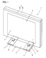
- the present invention relates to a display device provided with a display section having a display surface such as a liquid crystal panel and a stand section which supports this display section, and more particularly, to a display device which can change an angle of mounting the display section on the stand section.
- Patent Document 1 proposes a freestanding display device which constructs a display section by covering a liquid crystal panel with a front cabinet and back cabinet, provides a stand which supports this display section with a bracket that fixes the display section and attaches the stand column to this bracket in a freely pivotable manner so as to make the mounting angle of the display section variable.
- Patent Document 2 discloses a liquid crystal display monitor which attaches a stand column to a stand section in a freely pivotable manner as in the case of Patent Document 1 and also provides locking means for keeping an angle of the display section at a bottom plate of the stand.
- the present invention is implemented in view of the above described problems and it is an object of the present invention to provide a display device capable of changing the inclination of a display section according to the user's preferences and stably keeping the angle of the display section.
- the display device is a display device comprising a display section, a front side of which is used as a display plane, legs vertically provided beneath the display section and a stand section which supports the legs, wherein the stand section comprises a fixed plate and a cover which covers the fixed plate and fixes the fixed plate, and the fixed plate is provided with a plurality of fixed sections which fix the legs and make a mounting angle of the display section variable with respect to at least the stand section.
- the display device is the display device according to aspect 1, wherein the fixed section comprises an inclined plane which causes the display section to incline forward or backward with respect to the stand section and a horizontal fixed section which places the display plane in an upright position with respect to the stand section, the inclined planes and horizontal fixed section are arranged in parallel on the fixed plate, and the legs are selectively fixed to any one of the horizontal fixed section and the inclined planes according to the mounting angle of the display section.
- the fixed section comprises an inclined plane which causes the display section to incline forward or backward with respect to the stand section and a horizontal fixed section which places the display plane in an upright position with respect to the stand section
- the inclined planes and horizontal fixed section are arranged in parallel on the fixed plate, and the legs are selectively fixed to any one of the horizontal fixed section and the inclined planes according to the mounting angle of the display section.
- the display section when the horizontal substrate is mounted on the fixed plate, if the legs are fixed to the horizontal substrate, the display section is placed in an upright position with respect to the stand section and if the backward inclined substrate is mounted, the display section is inclined backward with respect to the stand section with the inclination of the inclined planes. Furthermore, if the forward inclined substrate is mounted, the display section is inclined forward with respect to the stand section with the inclination of the inclined planes.
- the display device according to aspect 4 of the present invention is the display device according to aspect 1, wherein a plurality of fixed plates having the horizontal fixed section provided with inclined planes which cause the display section to incline forward or backward as one piece with respect to the stand section and a flat fixed plate which places the display plane in an upright position with respect to the stand section are molded individually and the respective fixed plates are fixed to the cover according to the mounting angle of the display section.
- the display section is placed in an upright position with respect to the stand section and if the fixed plate with the backward inclined plane formed as one piece is fixed, the display section is inclined backward with respect to the stand section with the inclination of the inclined planes. Furthermore, if the fixed plate with the forward inclined plane formed as one piece is fixed, the display section is inclined forward with respect to the stand section with the inclination of the inclined planes.
- the display device of a first aspect of the present invention it is possible to easily change the mounting angle of the display section with respect to the stand section according to the angle of the fixed section and extremely stably support the legs by directly fixing the legs to the fixed plate without the angle of the display plane being changed by the own weight of the display section.
- the display device of a second aspect of the present invention it is possible to selectively fix the display section with respect to the fixed plate at any one of mounting angles of backward inclination, forward inclination and upright position.
- the cabinet 3 is divided into front and rear portions; a front cabinet 3a and a rear cabinet 3b, the front cabinet 3a is provided with a display window 4 which exposes a display plane 2a of the liquid crystal panel 2 and a stepped section 6 for attaching a pair of left and right legs 5 is formed below the rear cabinet 3b.
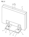
- the display section 1 is fixed to the stand section 7.
- the display section 1 is kept in an upright position with respect to the stand section 7.
- the display section 1 is inclined backward with respect to the stand section 7 due to the inclination of the inclined planes 14A and if the legs 5 are fixed to the inclined planes 14B of the fixed sections 13B as shown in FIG. 7A, the display section 1 is inclined forward with respect to the stand section 7 due to the inclination of the inclined planes 14B.
- the position of the horizontal fixed section 13C is substantially in the center of the cover 11 as shown in FIG. 5B.
- the fixed plate 10 to be fixed to the cover 11 is rotated clockwise from the state in FIG. 5A and the inclined plane 14A is located substantially in the center of the cover 11 and fixed as shown in FIG. 6B.
- the fixed plate 10 is turned over from the state in FIG. 6B and the inclined plane 14B is located substantially in the center of the cover 11 and fixed as shown in FIG. 7B. At this time, it is possible to easily check the orientation of the fixed plate 10 to be fixed to the cover 11 through the checking recess 20 formed in the fixed plate 10.
- the simple structure with two inclined planes 14A, 14B and horizontal fixed section 13C formed on the fixed plate 10 through press work or the like allows the manufacturing cost to be reduced.
- this embodiment forms the checking recess 20 in the fixed plate 10 as a guide to locate the positions at which the fixed sections 13A to 13C are formed with respect to the stand section 7 when the fixed plate 10 is fixed to the cover 11, which facilitates the attachment of the fixed plate to the cover 11.
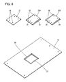
- FIG. 8 shows exploded perspective views of a fixed plate and horizontal substrate and inclined substrate according to a second embodiment of the present invention and parts having the same functions as those in the aforementioned first embodiment are assigned the same reference numerals, explanations of overlapping parts are omitted and only different parts will be explained.
- Embodiment 1 described above has shown an example where the fixed plate 10 is rotated or turned over and the fixed sections 13A to 13C are arranged at predetermined positions of the cover 11, while this embodiment will explain, as shown in FIG. 8, a case where a horizontal substrate 21 and two inclined substrates 22A, 22B of different angles of inclination are molded and those three types of substrates 21, 22A and 22B are mounted on a fixed plate 10 according to the mounting angle of a display section 1 in a freely detachable manner.
- the inclined substrates 22A, 22B are constructed of inclined planes 25, 26 corresponding to the mounting angle of the display section 1 formed in mounting seats 23, 24 respectively as a single piece and the horizontal substrate 21 has a flat rectangular shape having the same dimensions as the mounting seats 23, 24.
- the horizontal substrate 21 is mounted in the stepped recess 28 of the fixed plate 10 and a leg 5 is fixed to the horizontal substrate 21.
- any one of the mounting seats 23, 24 of the inclined substrates 22A, 22B is mounted in the stepped recess 28 of the fixed plate 10 and screwed therein.
- the horizontal substrate 21, inclined substrates 22A, 22B to be fixed to the fixed plate 10 in a freely detachable manner are formed and any one of the horizontal substrate 21, inclined substrates 22A, 22B is fixed to the fixed plate 10, and it is thereby possible, as in the case of the first embodiment, to cause the horizontal substrate 21 or inclined substrates 22A, 22B selectively mounted on the fixed plate 10 to change the mounting angle of the display section 1.
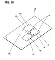
- FIG. 9 shows perspective views of a fixed plate according to a third embodiment of the present invention and parts having the same functions as those in the foregoing embodiments are assigned the same reference numerals, explanations of overlapping parts will be omitted and only different parts will be explained.
- the above described second embodiment has shown the example where the horizontal substrate 21, inclined substrates 22A, 22B are formed according to the mounting angle of the display section 1 with respect to the common fixed plate 10 and each substrate is fixed to the fixed plate 10.
- four types of fixed plates 30, 32, 34, 36 are individually formed; a flat fixed plate 30 having a horizontal fixed section 29, a fixed plate 32 in which an inclined plane 31 inclined backward is formed as one piece, a fixed plate 34 in which an inclined plane 33 of a smaller inclination than the inclined plane 31 of the fixed plate 32 is formed as one piece and a fixed plate 36 in which an inclined plane 35 inclined forward is formed.
Landscapes
- Engineering & Computer Science (AREA)
- General Engineering & Computer Science (AREA)
- Mechanical Engineering (AREA)
- Devices For Indicating Variable Information By Combining Individual Elements (AREA)
Applications Claiming Priority (1)
| Application Number | Priority Date | Filing Date | Title |
|---|---|---|---|
| JP2005305202A JP2007114445A (ja) | 2005-10-20 | 2005-10-20 | 表示装置 |
Publications (2)
| Publication Number | Publication Date |
|---|---|
| EP1777453A2 true EP1777453A2 (de) | 2007-04-25 |
| EP1777453A3 EP1777453A3 (de) | 2007-12-26 |
Family
ID=37680583
Family Applications (1)
| Application Number | Title | Priority Date | Filing Date |
|---|---|---|---|
| EP06255315A Withdrawn EP1777453A3 (de) | 2005-10-20 | 2006-10-16 | Anzeigevorrichtung |
Country Status (3)
| Country | Link |
|---|---|
| US (1) | US20070091554A1 (de) |
| EP (1) | EP1777453A3 (de) |
| JP (1) | JP2007114445A (de) |
Cited By (1)
| Publication number | Priority date | Publication date | Assignee | Title |
|---|---|---|---|---|
| CN102194377A (zh) * | 2010-02-17 | 2011-09-21 | 索尼西班牙股份有限公司 | 电视机支架 |
Families Citing this family (5)
| Publication number | Priority date | Publication date | Assignee | Title |
|---|---|---|---|---|
| US20090095869A1 (en) * | 2007-10-12 | 2009-04-16 | Joel Hazzard | Convertible display stand system and method |
| WO2015003326A1 (zh) * | 2013-07-09 | 2015-01-15 | 三洋科技中心(深圳)有限公司 | 一种电子装置 |
| US10412842B2 (en) * | 2015-12-07 | 2019-09-10 | Panasonic Intellectual Property Management Co., Ltd. | Image display device |
| CN110895187B (zh) * | 2019-12-25 | 2025-03-25 | 江门市鹏程头盔有限公司 | 用于摩托车头盔强度检测的辅助装置 |
| JP2023151297A (ja) * | 2022-03-31 | 2023-10-16 | 富士フイルム株式会社 | 処理装置、及び画像形成装置 |
Family Cites Families (10)
| Publication number | Priority date | Publication date | Assignee | Title |
|---|---|---|---|---|
| US4368867A (en) * | 1981-06-29 | 1983-01-18 | Honeywell Information Systems Inc. | Tilt base for a CRT display terminal |
| JP3236707B2 (ja) * | 1993-08-10 | 2001-12-10 | 富士通株式会社 | 自立型ディスプレイ装置 |
| BE1007734A6 (nl) * | 1993-11-10 | 1995-10-10 | Cladakis Nikolas | Steun voor opname- en projectieapparaten, meer bepaald filmcamera's. |
| US6288891B1 (en) * | 1996-11-21 | 2001-09-11 | Canon Kabushiki Kaisha | Movable display apparatus |
| JPH1117354A (ja) * | 1997-06-27 | 1999-01-22 | Matsushita Electric Ind Co Ltd | 映像機器の搭載台 |
| JPH11258580A (ja) * | 1998-03-16 | 1999-09-24 | Hitachi Ltd | 液晶表示モニタ |
| JP2001166849A (ja) * | 1999-12-08 | 2001-06-22 | Toshiba Corp | 液晶ディスプレイ、コンピュータ及びスタンド付き液晶ディスプレイ |
| JP3511506B2 (ja) * | 2000-11-08 | 2004-03-29 | 富士通株式会社 | ディスプレイの支持装置 |
| US6741458B2 (en) * | 2002-09-12 | 2004-05-25 | Amtran Technology Co. Ltd. | Stand for a flat panel display |
| KR20050023576A (ko) * | 2003-08-28 | 2005-03-10 | 삼성전자주식회사 | 디스플레이장치 |
-
2005
- 2005-10-20 JP JP2005305202A patent/JP2007114445A/ja active Pending
-
2006
- 2006-10-16 EP EP06255315A patent/EP1777453A3/de not_active Withdrawn
- 2006-10-19 US US11/583,166 patent/US20070091554A1/en not_active Abandoned
Cited By (1)
| Publication number | Priority date | Publication date | Assignee | Title |
|---|---|---|---|---|
| CN102194377A (zh) * | 2010-02-17 | 2011-09-21 | 索尼西班牙股份有限公司 | 电视机支架 |
Also Published As
| Publication number | Publication date |
|---|---|
| JP2007114445A (ja) | 2007-05-10 |
| EP1777453A3 (de) | 2007-12-26 |
| US20070091554A1 (en) | 2007-04-26 |
Similar Documents
| Publication | Publication Date | Title |
|---|---|---|
| CN101311998B (zh) | 平板显示器和具有该平板显示器的平板显示装置 | |
| US7651062B2 (en) | LCD apparatus | |
| US9097923B2 (en) | Liquid crystal module assembly and display device including the same | |
| US6671012B1 (en) | Mounting member for fixing a display panel to a display unit body | |
| KR20180024713A (ko) | 디스플레이 장치 | |
| US20070235626A1 (en) | Angle adjustment apparatus for electronic device | |
| US20080100589A1 (en) | Bezel assembly for assembling touch panel with LCD device | |
| US20060077623A1 (en) | Display device | |
| US20100149734A1 (en) | Display apparatus | |
| JP4453717B2 (ja) | 表示装置 | |
| EP1777453A2 (de) | Anzeigevorrichtung | |
| US8009414B2 (en) | Electronic equipment and shelf member | |
| KR102725640B1 (ko) | 월 마운트 고정장치 및 이를 갖는 디스플레이 장치 | |
| KR101416905B1 (ko) | 듀얼 모니터 장치 | |
| JP4645626B2 (ja) | 薄型表示装置 | |
| KR20050109310A (ko) | 디스플레이 장치 | |
| JP4749731B2 (ja) | ラックマウント | |
| JP2007206278A (ja) | 支持スタンド及び表示装置 | |
| US20250049215A1 (en) | Wall mount fixture and display apparatus having the same | |
| US20050152103A1 (en) | Flat panel display | |
| JP4434188B2 (ja) | 電子機器及びテレビジョン受像機 | |
| US8925879B2 (en) | Horizontal type display device | |
| JP2008249924A (ja) | スタンド装置 | |
| EP3945234A1 (de) | Anzeigevorrichtung | |
| JP4059096B2 (ja) | プラズマディスプレイ装置 |
Legal Events
| Date | Code | Title | Description |
|---|---|---|---|
| PUAI | Public reference made under article 153(3) epc to a published international application that has entered the european phase |
Free format text: ORIGINAL CODE: 0009012 |
|
| AK | Designated contracting states |
Kind code of ref document: A2 Designated state(s): AT BE BG CH CY CZ DE DK EE ES FI FR GB GR HU IE IS IT LI LT LU LV MC NL PL PT RO SE SI SK TR |
|
| AX | Request for extension of the european patent |
Extension state: AL BA HR MK YU |
|
| PUAL | Search report despatched |
Free format text: ORIGINAL CODE: 0009013 |
|
| AK | Designated contracting states |
Kind code of ref document: A3 Designated state(s): AT BE BG CH CY CZ DE DK EE ES FI FR GB GR HU IE IS IT LI LT LU LV MC NL PL PT RO SE SI SK TR |
|
| AX | Request for extension of the european patent |
Extension state: AL BA HR MK YU |
|
| 17P | Request for examination filed |
Effective date: 20080416 |
|
| 17Q | First examination report despatched |
Effective date: 20080609 |
|
| AKX | Designation fees paid |
Designated state(s): DE FR GB |
|
| GRAP | Despatch of communication of intention to grant a patent |
Free format text: ORIGINAL CODE: EPIDOSNIGR1 |
|
| STAA | Information on the status of an ep patent application or granted ep patent |
Free format text: STATUS: THE APPLICATION IS DEEMED TO BE WITHDRAWN |
|
| 18D | Application deemed to be withdrawn |
Effective date: 20090505 |