EP1777616A2 - Speichersystem und Speichersteuerungsvorrichtung - Google Patents
Speichersystem und Speichersteuerungsvorrichtung Download PDFInfo
- Publication number
- EP1777616A2 EP1777616A2 EP07001832A EP07001832A EP1777616A2 EP 1777616 A2 EP1777616 A2 EP 1777616A2 EP 07001832 A EP07001832 A EP 07001832A EP 07001832 A EP07001832 A EP 07001832A EP 1777616 A2 EP1777616 A2 EP 1777616A2
- Authority
- EP
- European Patent Office
- Prior art keywords
- data
- volume
- storage
- storage device
- write request
- Prior art date
- Legal status (The legal status is an assumption and is not a legal conclusion. Google has not performed a legal analysis and makes no representation as to the accuracy of the status listed.)
- Withdrawn
Links
Images


Classifications
-
- G—PHYSICS
- G06—COMPUTING OR CALCULATING; COUNTING
- G06F—ELECTRIC DIGITAL DATA PROCESSING
- G06F3/00—Input arrangements for transferring data to be processed into a form capable of being handled by the computer; Output arrangements for transferring data from processing unit to output unit, e.g. interface arrangements
- G06F3/06—Digital input from, or digital output to, record carriers, e.g. RAID, emulated record carriers or networked record carriers
- G06F3/0601—Interfaces specially adapted for storage systems
- G06F3/0628—Interfaces specially adapted for storage systems making use of a particular technique
- G06F3/0662—Virtualisation aspects
- G06F3/0665—Virtualisation aspects at area level, e.g. provisioning of virtual or logical volumes
-
- G—PHYSICS
- G06—COMPUTING OR CALCULATING; COUNTING
- G06F—ELECTRIC DIGITAL DATA PROCESSING
- G06F11/00—Error detection; Error correction; Monitoring
- G06F11/07—Responding to the occurrence of a fault, e.g. fault tolerance
- G06F11/16—Error detection or correction of the data by redundancy in hardware
- G06F11/20—Error detection or correction of the data by redundancy in hardware using active fault-masking, e.g. by switching out faulty elements or by switching in spare elements
- G06F11/2053—Error detection or correction of the data by redundancy in hardware using active fault-masking, e.g. by switching out faulty elements or by switching in spare elements where persistent mass storage functionality or persistent mass storage control functionality is redundant
- G06F11/2056—Error detection or correction of the data by redundancy in hardware using active fault-masking, e.g. by switching out faulty elements or by switching in spare elements where persistent mass storage functionality or persistent mass storage control functionality is redundant by mirroring
- G06F11/2071—Error detection or correction of the data by redundancy in hardware using active fault-masking, e.g. by switching out faulty elements or by switching in spare elements where persistent mass storage functionality or persistent mass storage control functionality is redundant by mirroring using a plurality of controllers
-
- G—PHYSICS
- G06—COMPUTING OR CALCULATING; COUNTING
- G06F—ELECTRIC DIGITAL DATA PROCESSING
- G06F11/00—Error detection; Error correction; Monitoring
- G06F11/07—Responding to the occurrence of a fault, e.g. fault tolerance
- G06F11/16—Error detection or correction of the data by redundancy in hardware
- G06F11/20—Error detection or correction of the data by redundancy in hardware using active fault-masking, e.g. by switching out faulty elements or by switching in spare elements
- G06F11/2053—Error detection or correction of the data by redundancy in hardware using active fault-masking, e.g. by switching out faulty elements or by switching in spare elements where persistent mass storage functionality or persistent mass storage control functionality is redundant
- G06F11/2056—Error detection or correction of the data by redundancy in hardware using active fault-masking, e.g. by switching out faulty elements or by switching in spare elements where persistent mass storage functionality or persistent mass storage control functionality is redundant by mirroring
- G06F11/2082—Data synchronisation
-
- G—PHYSICS
- G06—COMPUTING OR CALCULATING; COUNTING
- G06F—ELECTRIC DIGITAL DATA PROCESSING
- G06F3/00—Input arrangements for transferring data to be processed into a form capable of being handled by the computer; Output arrangements for transferring data from processing unit to output unit, e.g. interface arrangements
- G06F3/06—Digital input from, or digital output to, record carriers, e.g. RAID, emulated record carriers or networked record carriers
- G06F3/0601—Interfaces specially adapted for storage systems
- G06F3/0602—Interfaces specially adapted for storage systems specifically adapted to achieve a particular effect
- G06F3/0604—Improving or facilitating administration, e.g. storage management
- G06F3/0605—Improving or facilitating administration, e.g. storage management by facilitating the interaction with a user or administrator
-
- G—PHYSICS
- G06—COMPUTING OR CALCULATING; COUNTING
- G06F—ELECTRIC DIGITAL DATA PROCESSING
- G06F3/00—Input arrangements for transferring data to be processed into a form capable of being handled by the computer; Output arrangements for transferring data from processing unit to output unit, e.g. interface arrangements
- G06F3/06—Digital input from, or digital output to, record carriers, e.g. RAID, emulated record carriers or networked record carriers
- G06F3/0601—Interfaces specially adapted for storage systems
- G06F3/0602—Interfaces specially adapted for storage systems specifically adapted to achieve a particular effect
- G06F3/0604—Improving or facilitating administration, e.g. storage management
- G06F3/0607—Improving or facilitating administration, e.g. storage management by facilitating the process of upgrading existing storage systems, e.g. for improving compatibility between host and storage device
-
- G—PHYSICS
- G06—COMPUTING OR CALCULATING; COUNTING
- G06F—ELECTRIC DIGITAL DATA PROCESSING
- G06F3/00—Input arrangements for transferring data to be processed into a form capable of being handled by the computer; Output arrangements for transferring data from processing unit to output unit, e.g. interface arrangements
- G06F3/06—Digital input from, or digital output to, record carriers, e.g. RAID, emulated record carriers or networked record carriers
- G06F3/0601—Interfaces specially adapted for storage systems
- G06F3/0628—Interfaces specially adapted for storage systems making use of a particular technique
- G06F3/0646—Horizontal data movement in storage systems, i.e. moving data in between storage devices or systems
- G06F3/065—Replication mechanisms
-
- G—PHYSICS
- G06—COMPUTING OR CALCULATING; COUNTING
- G06F—ELECTRIC DIGITAL DATA PROCESSING
- G06F3/00—Input arrangements for transferring data to be processed into a form capable of being handled by the computer; Output arrangements for transferring data from processing unit to output unit, e.g. interface arrangements
- G06F3/06—Digital input from, or digital output to, record carriers, e.g. RAID, emulated record carriers or networked record carriers
- G06F3/0601—Interfaces specially adapted for storage systems
- G06F3/0668—Interfaces specially adapted for storage systems adopting a particular infrastructure
- G06F3/067—Distributed or networked storage systems, e.g. storage area networks [SAN], network attached storage [NAS]
-
- G—PHYSICS
- G06—COMPUTING OR CALCULATING; COUNTING
- G06F—ELECTRIC DIGITAL DATA PROCESSING
- G06F11/00—Error detection; Error correction; Monitoring
- G06F11/07—Responding to the occurrence of a fault, e.g. fault tolerance
- G06F11/16—Error detection or correction of the data by redundancy in hardware
- G06F11/1658—Data re-synchronization of a redundant component, or initial sync of replacement, additional or spare unit
- G06F11/1662—Data re-synchronization of a redundant component, or initial sync of replacement, additional or spare unit the resynchronized component or unit being a persistent storage device
Definitions
- the present invention relates to a storage system and a storage control device.
- data is controlled using relatively large-scale storage systems in order to handle large quantities of various types of data in government organizations, public offices, autonomous regional bodies, business enterprises, educational organizations and the like.
- storage systems are constructed from disk array devices or the like.
- Disk array devices are constructed by disposing numerous storage devices in the form of an array; for example, a storage region based on an RAID (redundant array of independent disks) is provided.
- One or more logical volumes are formed in a physical storage region provided by a storage device group, and these logical volumes are provided to a host computer (more specifically, to a data base program operating in a host computer).
- the host computer (hereafter abbreviated to "host") can perform the reading and writing of data with respect to the logical volumes by transmitting specified commands.
- such cases include cases in which the old type of storage device is a device that involves mechanical operations (such as head seeking or the like), so that the mechanical operating time is long, cases in which the capacity of the data transfer buffer of the old type of storage device is small, and the like.
- the present invention was devised in light of the above problems.
- One object of the present invention is to provide a storage system and storage control device which are devised so that different types of storage control devices such as new and old storage control devices can be caused to cooperate, thus allowing effective utilization of memory resources.
- Another object of the present invention is provide a storage system and storage control device which allow the utilization of an old type of storage control device as a new type of storage control device.
- Another object of the present invention is to provide a storage system and storage control device which are devised so that new functions can be added while utilizing the advantages of an old type of storage device.
- Another object of the present invention is to provide a storage system and storage control device which are devised so that the memory resources of a second storage control device can be incorporated into a first storage control device as a first virtual volume, and the storage contents of the first real volume of the first storage control device and this first virtual volume can be synchronized.
- a first aspect of the present invention is a storage system which is constructed by communicably connecting a first storage control device and a second storage control device, and which performs data processing in accordance with requests from a higher device, wherein the abovementioned first storage control device comprises a first real volume, a first virtual volume that can form a copying pair with the first real volume, a first control part that respectively controls data communications between the first real volume and first virtual volume, and the higher device and second storage control device, and a synchronizing part that synchronizes the storage contents of the first real volume and the storage contents of the first virtual volume, and the second storage control device comprises a second real volume that is associated with the first virtual volume, and a second control part that respectively controls data communications between the second real volume, and the higher device and first storage control device.
- the first storage control device respectively comprises a first real volume and a first virtual volume.
- the first real volume is constructed on the basis of first storage device which has a first storage control device
- the first virtual volume is constructed on the basis of a second storage device which has a second storage control device.
- the first storage control part incorporates the memory resources of the second storage control device as though these memory resources were its own memory resources, and provides these memory resources to the higher device. Furthermore, the synchronizing part synchronizes the storage contents of the first real volume and first virtual volume. Accordingly, a backup of the first real volume can be formed in the first virtual volume, and conversely, a backup of the first virtual volume can be formed in the first real volume.
- the synchronization modes can be divided into two main types: namely, a full copying mode in which all of the storage contents are copied, and a differential copying mode in which only the differential data is copied.
- the first storage control device has a first storage device
- the second storage control device has a second storage device; furthermore, the first real volume is connected to the first storage device via an intermediate storage device, and the first virtual volume is connected to the second storage device via a virtually constructed virtual intermediate storage device.
- the intermediate storage device is a storage hierarchy which logically connects the first storage device that provides a physical storage region, and the first virtual volume.
- the virtual intermediate storage device is a storage hierarchy which logically connects the second storage device that provides a physical storage region, and the first virtual volume.
- the virtual intermediate storage device is associated with the storage region of the second storage device of the second storage control device. Specifically, by mapping the second storage device in the virtual intermediate storage device, it is possible to vary the storage capacity, or to employ a stripe structure or the like.
- the synchronizing part can copy the entire storage contents stored in the first real volume into the first virtual volume. Conversely, the synchronizing part can also copy the entire storage contents stored in the first virtual volume into the first real volume.
- the synchronizing part can also copy the differential data between the storage contents of the first real volume and the storage contents of the first virtual volume into the first virtual volume.
- the copying pair consisting of the two volumes is temporarily released (split). Then, in cases where a change occurs in the storage contents of the first virtual volume as a result of a write request from the higher device, the storage contents of the two volumes can again be caused to coincide by separately controlling the this changed differential data, and copying only this differential data into the first real volume.
- the synchronizing part can copy the differential data into the first virtual volume. As a result, the storage contents of both volumes can be matched.
- the system further comprises a managing device which is communicably connected to the first storage control device and second storage control device, respectively. Furthermore, in cases where the access attribute of "write prohibited" is set in the first real volume by the managing device, the synchronizing part copies the differential data into the first virtual volume, and when the copying of the differential data is completed, the managing device can set the access attribute of the first real volume as "read and write possible”.
- the function of the managing device can be constructed from a computer program. Accordingly, for example, the managing device can be constructed as a computer device that is separate from the higher device, or can be installed inside the higher device.
- the term "access attribute” refers to information that is used to control whether or not a given volume can be accessed. Examples of access attributes include "write prohibited (read only)” which prohibits the updating of data, “read/write possible” which allows both the reading and writing of data, "hidden” which does not respond to inquiry responses, "empty capacity 0" which responds that the state is full in the case of inquiries for empty capacity, and the like.
- the synchronizing part can also copy differential data between the storage contents of the first real volume and the storage contents of the first virtual volume into the first real volume. Furthermore, in this case, the synchronizing part can acquire differential control information relating to the differential data from the second storage control device, and can read out differential data from the second storage control device and copy this data into the first real volume on the basis of this differential control information.
- the synchronizing part can maintain the matching of data by copying the differential data into the first real volume.
- the synchronizing part can copy the differential data into the first real volume, and when the copying of this differential data has been completed, the managing device can also set the access attribute of the second real volume as "read and write possible".
- the storage system is a storage system in which a first storage control device and a second storage control device are communicably connected, this storage system comprising a higher device that can respectively issue access requests to the first storage control device and second storage control device, and a managing device that can communicate with the first storage control device and second storage control device
- the first storage control device comprises a first storage device that stores data, an intermediate storage device that is disposed in the storage region of this first storage device, a first real volume that is disposed in the storage region of this intermediate storage device, a virtual intermediate storage device that is disposed in the storage region of the second storage device of the second storage control device, a first virtual volume that is disposed in the storage region of this virtual intermediate storage device, a higher communications control part that respectively controls data communications between the higher device, and the second storage control device and managing device, a lower communications control part that controls data communications with the first storage device, a memory part that is shared by the higher communications control part and lower communications control part, and a mapping table that is stored in the
- the higher communications control part refers to the mapping table and reads out all of the data from the second real volume, and the lower communications control part stores all of this read-out data in the first storage device.
- the lower communications control part reads out all of the data of the first real volume from the first storage device, and the higher communications control part refers to the mapping table and writes this read-out data into the second real volume.
- the first storage control device and second storage control device can respectively hold differential control information that controls the differential data between the storage contents of the first real volume and the storage contents of the first virtual volume.
- the lower communications control part reads out the differential data from the first storage device, and the higher communications control part refers to the mapping table and writes this read-out differential data into the second real volume.
- the higher communications control part reads out the differential control information controlled by the second storage control device, refers to this read-out differential control information and the mapping table, and reads out the differential data from the second real volume, and the lower communications control part stores this read-out differential data in the first storage device.
- the present invention may also be understood as the invention of a storage control device.
- the present invention may also be understood as a copying control method for a storage control device.
- this copying control method can be constructed so as to comprise the steps of mapping the second real volume of a second storage control device into the first virtual volume of a first storage control device, setting the abovementioned first virtual volume and the first real volume of the abovementioned first storage control device as a copying pair, and causing the storage contents of the abovementioned first virtual volume and the abovementioned first real volume to coincide.
- Fig. 1 is a structural explanatory diagram which shows an overall outline of an embodiment of the present invention.
- the storage system maps a storage device present on the outside into its own intermediate storage device (VDEV), thus incorporating this external storage device as thought this device were its own internal volume, and provides this volume to a host.
- VDEV intermediate storage device
- the storage system of the present embodiment can comprise a first storage device 1 which is one example of a first storage control device, a second storage device 2 which is one example of a second storage control device, a host 3 which acts as a higher device, and a managing device 4.
- the first storage device 1 is constructed as a disk array device.
- the first storage device 1 comprises three communications ports 1A through 1C; the host 3, managing device 4 and second storage device 2 are communicably connected by means of these respective communications ports.
- data communications can be performed between the respective storage devices 1 and 2, and the respective storage devices 1 and 2 and the host 3, on the basis of a fiber channel protocol.
- data communications can be performed between the respective storage devices 1 and 2 and the managing device 4 on the basis of a TCP/IP (transmission control protocol/internet protocol).
- TCP/IP transmission control protocol/internet protocol
- the first storage device 1 can comprise a control part 5, an internal volume 6 used as a first real volume, and a virtual internal volume 7 used as a first virtual volume.
- the control part 5 respectively controls the exchange of data inside the first storage device and the exchange of data with the outside.
- the internal volume 6 is disposed on the basis of a physical storage device (e. g., a disk drive) disposed inside the first storage device 1.
- the virtual internal volume 7 has a virtual existence; the entity that stores data is present inside the second storage device 2. Specifically, the virtual internal volume 7 is constructed by mapping an external volume 9 of the second storage device 2 into a specified level of the storage hierarchy of the first storage device 1.
- the control part 5 comprises a differential bit map 5A and a mapping table 5B.
- the differential bit map 5A comprises information that is used to control the differential between the storage contents of the internal volume 6 and the storage contents of the virtual internal volume 7 (external volume 9).
- differential data 6A is generated by this updating.
- the differential bit map 5A comprises information that is used to control this differential data 6A.
- the mapping table 5B comprises information that is used to associate the external volume 9 with the virtual internal volume 7; for example, this information includes path information or the like that is used to access the external volume 9.
- the second storage device 2 is communicably connected with the host 3, managing device 4 and first storage device 1, respectively via respective communications ports 2A through 2C.
- the second storage device 2 can be constructed so that this device comprises a control part 8 and an external volume 9.
- the control part 8 respectively controls the exchange of data within the second storage device 2 and the exchange of data with the outside.
- the external volume 9 is disposed on the basis of a physical storage device disposed inside the second storage device 2. Since the volumes of the second storage device 2 are present on the outside as seen from the first storage device 1, these volumes are called external volumes here.
- the control part 8 comprises a differential bit map 8A that is used to control the differential data 9A that is generated in the external volume 9.
- the internal volume 6 and virtual internal volume 7 form a copying pair. Either of these volumes may be the copying source, and either of the volumes may be the copying destination.
- the method used to synchronize the storage contents there is full copying in which all of the storage contents of the copying source volume are copied into the copying destination volume, and differential copying in which the only the differential data between the copying source volume and copying destination volume is copied; either of these methods may be employed.
- control part 5 In cases where data is copied from the internal volume 6 into the virtual internal volume 7, the control part 5 refers to the mapping table 5B, acquires path information relating to the path to the external volume 9 which is the entity of the of the virtual internal volume 7, and transfers data to the external volume 9. Similarly, furthermore, in cases where data is copied from the virtual internal volume 7 into the internal volume 6, the control part 5 refers to the mapping table 5B, acquires path information relating to the path to the external volume 9, and writes data read out from the external volume 9 into the internal volume 6.
- the data of the internal volume 6 and the data of the virtual internal volume 7 can be synchronized.
- the present embodiment will be described in greater detail below.
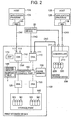
- Fig. 2 is a block diagram which shows the construction of the essential parts of the storage system of the present embodiment.
- the hosts 10A and 10B are computer devices comprising information processing resources such as a CPU (central processing unit), memory and the like; for instance, these hosts are constructed as personal computers, workstations, main frames or the like.
- the host 10A comprises an HBA (host bus adapter) 11A that is used to access a first storage device 100 via a communications network CN1, and (for example) an application program 12A such as data base software or the like.
- the host 10B also comprises an HBA 11B that is used to access a second storage device 200, and an application program 12B.
- HBA host bus adapter
- these parts will be referred to simply as hosts 10, HBA 11 and application programs 12.
- an LAN local area network
- an SAN storage area network
- the internet a dedicated circuit, a public circuit or the like
- data communications via an LAN are performed according to a TCP/IP protocol.
- the hosts 10 In cases where the hosts 10 are connected to the first storage device 100 [and second storage device] 200 via an LAN, the hosts 10 request data input and output in file units by designating file names.
- the hosts 10 request data input and output with blocks (which are the units of data control of the storage regions provided by a plurality of disk storage devices (disk drives)) in accordance with a fiber channel protocol.
- the HBA 11 is (for example) a network card corresponding to this LAN.
- the HBA 11 is (for example) a host bus adapter.
- the managing device 20 is a computer device which is used to control the construction of the storage system and the like. For example, this device is operated by a user such as a system manager or the like.
- the managing device 20 is respectively connected to the respective storage devices .100 and 200 via a communications network CN2.
- the managing device 20 issues instructions relating to the formation of copying pairs, access attributes and the like to the respective storage devices 100 and 200.
- the first storage device 100 is constructed as a disk array subsystem.
- the present invention is not limited to this; the first storage device 100 can also be constructed as a highly functionalized intelligent type fiber channel switch.
- the first storage device 100 can provide the memory resources of the second storage device 200 to the host 10 as its own logical volume (logical unit).
- the first storage device 100 can be divided into two main parts, i. e., a controller and a storage part 160.
- the controller comprises a plurality of channel adapters (hereafter referred to as "CHAs") 110, a plurality of disk adapters (hereafter referred to as "DKAs") 120, a cache memory 130, a shared memory 140, and a connection control part 150.
- CHOKs channel adapters
- DKAs disk adapters
- Each CHA 110 performs data communications with a host 10.
- Each CHA 110 comprises a communications port 111 for performing communications with this host 10.
- the respective CHAs 110 are constructed as microcomputer systems comprising a CPU, memory and the like; these CHAs 110 interpret and execute various types of commands received from the hosts 10.
- Network addresses used to discriminate the respective CHAs 110 e. g., IP addresses or WWN
- each CHA 110 can behave separately as an NAS (network attached storage).
- the respective CHAs 110 separately receive and process requests from the respective hosts 10.
- Each DKA 120 exchanges data with a disk drive 161 of the control part 160.
- each DKA 120 is constructed as a microcomputer system comprising a CPU, memory and the like.
- the respective DKAs 120 write data received from the host 10 or read out from the second storage device 200 by the CHAs 110 into a specified address of a specified disk drive 161.
- each DKA 120 reads out data from a specified address of a specified disk drive 161, and transmits this data to a host 10 or the second storage device 200.
- each DKA 120 converts the logical address into a physical address.
- each DKA 120 accesses data according to the RAID construction. For example, each DKA 120 writes the same data into different disk drive groups (RAID groups), or performs parity calculations and writes the data and parity into the disk drive groups.
- RAID groups disk drive groups
- the cache memory 130 stores data received from the host 10 or second storage device 200, or stores data read out from the disk drive 161. As will be described later, a virtual intermediate storage device is constructed utilizing the storage space of the cache memory 130.
- control information used in the operation of the first storage device 100 are stored in the shared memory (also called a control memory in some cases) 140. Furthermore, in addition to the setting of a work region, various types of tables such as the mapping table and the like described later are also stored in the shared memory 140.
- one or a plurality of disk drives 161 can also be used as cache disks.
- the cache memory 130 and shared memory 140 can be constructed as respectively separate memories, or some of the storage regions of the same memory can be used as cache regions, and other storage regions can be used as control regions.
- connection control part 150 connects the respective CHAs 110, the respective DKAs 120, the cache memory 130 and the shared memory 140 to each other.
- the connection control part 150 can be constructed as a high-sped bus such as an ultra-high-speed cross-bar switch that performs data transfer by means of a high-speed switching operation.
- the storage part 160 comprises a plurality of disk drives 161.
- various types of storage disks such as hard disk drives, flexible disk drives, magnetic disk drives, semiconductor memory drives, optical disk drives or the like, or the equivalents of such drives, can be used as the disk drives 161.
- different types of disks may be mixed inside the storage part 160, as in FC (fiber channel) disks, SATA (serial AT attachment) disks or the like.
- a virtual internal volume 191 based on a disk drive 220 of the second storage device 200 can be formed in the first storage device 100.
- This virtual internal volume 191 can be provided to the host 10A in the same manner as the internal volume 190 based on the disk drive 161.
- the second storage device 200 comprises a controller 210 and a plurality of disk drives 220.
- the second storage device 200 is communicably connected with the host 10B, managing device 20 and first storage device 100, respectively via the communications port 211.
- the second storage device 200 and host 10B are connected via the communications network CN1.
- the second storage device 200 and managing device 20 are connected via the communications network CN2.
- the second storage device 200 and first storage device 100 are connected via the communications network CN3.
- the communications networks CN2 and CN3 can be constructed from SAN, LAN or the like.
- the second storage device 200 may have substantially the same construction as the first storage device, or may have a simpler construction than the first storage device 100.
- the disk drives 220 of the second storage device 200 may be handled as internal storage devices of the first storage device 100.
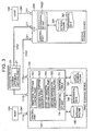
- Fig. 3 is a structural explanatory diagram focusing on the functional construction of the present embodiment.
- the controller 101 of the first storage device 100 is constructed from the CHAs 110, respective DKAs 120, cache memory 130, shared memory 140 and the like.
- this controller 101 comprises (for example) a first full copying control part 102, a second full copying control part 103, a first differential copying control part 104, and a second differential copying control part 105. Furthermore, various types of tables such as a mapping table T1, differential bit map T4 and the like are stored inside the shared memory 140 of the controller 101.
- the first full copying control part 102 is a function that copies all of the storage contents of the virtual internal volume 191 into the internal volume 190.
- the second full copying control part 103 is a function that copies all of the storage contents of the internal volume 190 into the virtual internal volume 191.
- the first differential copying control part 104 is a control that copies the differential data 192 of the internal volume 190 into the virtual internal volume 191.
- the second differential copying control part 105 is a function that copies the differential data 261 of the virtual internal volume 191 into the internal volume 190.
- the internal volume 190 and virtual internal volume 191 are respectively disposed in the first storage device 100.
- the internal volume 190 is a volume that is set on the basis of the storage regions of the respective disk drives 161 that are directly governed by the first storage device 100.
- the virtual internal volume 191 is a volume that is set on the basis of the storage regions of the respective disk drives 220 of the second storage device 200.
- the controller 210 of the second storage device 200 stores the differential bit map T4 (2) in a memory (not shown in the figures).
- This differential bit map T4 (2) is used to control the differential data 261 that is generated for the external volume 260 of the second storage device 200.
- the external volume 260 is based on the storage region of the disk drive 220, and is an internal volume with respect to the second storage device 200. However, since this volume 260 is mapped into the virtual internal volume 191 and incorporated into the first storage device 100, this volume is called the external volume 260 in the present embodiment.
- the managing device 20 comprises an access attribute setting part 21.
- This access attribute setting part 21 is used to set access attributes for the internal volume 190 or external volume 260.
- the setting of access attributes can be performed manually by the user, or can be performed automatically on the basis of some type of trigger signal. The types of access attributes will be further described later.
- Fig. 4 is a structural explanatory diagram which focuses on the storage structure of the first storage device 100 and second storage device 200. The construction of the first storage device 100 will be described first.
- the storage structure of the first storage device 100 can be roughly divided into a physical storage hierarchy and a logical storage hierarchy.
- the physical storage hierarchy is constructed by a PDEV (physical device) 161 which is a physical disk.
- the PDEV corresponds to a disk drive.
- the logical storage hierarchy can be constructed from a plurality (e. g., two types) of hierarchies.
- One logical hierarchy can be constructed from VDEVs (virtual devices) 162 and virtual VDEVs (hereafter called "V-VOLs") 163 which can be handled as VDEVs 162.
- V-VOLs virtual VDEVs
- the other logical hierarchy can be constructed from LDEVs (logical devices) 164.
- the VDEVs 162 can be constructed by forming a specified number of PDEVs 161 into a group, e.. g., four units as one set (3D + 1P), eight units as one set (7D + 1P) or the like.
- One RAID storage region is formed by the aggregate of the storage regions provided by the respective PDEVs 161 belonging to a group. This RAID storage region constitutes a VDEV 162.
- the V-VOL 163 is a virtual intermediate storage device which requires no physical storage region.
- the V-VOL 163 is not directly associated with a physical storage region, but is a receiver for the mapping of LUs (logical units) of the second storage device 200.
- One or more LDEVs 164 can be respectively disposed in the VDEV 162 or V-VOL 163.
- the LDEVs 164 can be constructed by splitting a VDEV 162 into specified lengths.
- the host 10 [involved] is an open type host
- the host 10 can recognize the LDEV 164 as a single physical disk by mapping the LDEV 164 in the LU 165.
- the open type host can access a desired LDEV 164 by designating the LUN (logical unit number) or logical block address.
- the LDEV 164 can be directly accessed.
- the LU 165 is a device that can be recognized as an SCSI logical unit.
- the respective LUs 165 are connected to the host 10 via a target port 111A.
- One or more LDEVs 164 can be respectively associated with each LU 165. It is also possible to expand the LU size virtually by associating a plurality of LDEVs 164 with one LU 165.
- the CMD (command device) 166 is a special LU that is used to transfer commands and status [information] between the I/O control program operating in the host 10 and the controller 101 (CHAs 110, DKAs 210) of the storage device 100. Commands from the host 10 are written into the CMD 166.
- the controller 101 of the storage device 100 executes processing corresponding to the commands that are written into the CMD 166, and writes the results of this execution into the CMD 166 as status [information].
- the host 10 reads out and confirms the status [information] that is written into the CMD 166, and then writes the processing contents that are to be executed next into the CMD 166.
- the host 10 can issue various types of instructions to the storage device 100 via the CMD 166.
- the commands received from the host 10 can also be processed without being stored in the CMD 166.
- the CMD can also be formed as a virtual device without defining the actual device (LU), and can be constructed so as to receive and process commands from the host 10.
- the CHAs 110 write the commands received from the host 10 into the shared memory 140
- the CHAs 110 or DKAs 120 process the commands stored in this shared memory 140.
- the processing results are written into the shared memory 140, and are transmitted to the host 10 from the CHAs 110.
- the second storage device 200 is connected to the external initiator port (external port) 111B of the first storage device 100 via the communications network CN3.
- the second storage device 200 comprises a plurality of PDEVs 220, VDEVs 230 that are set in storage regions provided by the PDEVs 220, and one or more LDEVs 240 that can be set in the VDEVs 230.
- Each LDEV 240 is respectively associated with an LU 250.
- the LUs 250 i. e., the LDEVs 240
- V-VOL 163 is a virtual intermediate storage device so that these LUs 250 can also be used from the first storage device 100.
- the "LDEV 1" and “LDEV 2" of the second storage device 200 are respectively mapped into the “V-VOL 1" and “V-VOL 2" of the first storage device 100 via the "LU 1" and “LU 2" of the second storage device 200. Furthermore, the "V-VOL 1" and “V-VOL 2" are respectively mapped into the “LDEV 3” and “LDEV 4", and can be utilized via the "LU 3" and "LU 4".
- VDEVs 162 and V-VOLs 163 can use an RAID construction. Specifically, one disk drive 161 can be divided into a plurality of VDEVs 162 and V-VOLs 163 (slicing), or one VDEV 162 or V-VOL 163 can be formed from a plurality of disk drives 161 (striping).
- the "LDEV 1" or “LDEV 2" of the first storage device 100 corresponds to internal volume 190 in Fig. 3.
- the "LDEV 3" or “LDEV 4" of the of the first storage device 100 corresponds to the virtual internal volume 191.
- the "LDEV 1" or “LDEV 2" of the second storage device 200 corresponds to the external volume 260 in Fig. 3.
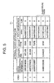
- Fig. 5 shows one example of the mapping table T1 that is used to map the external volume 260 into the virtual internal volume 191.
- mapping table T1 can be constructed by respectively establishing a correspondence between the VDEV numbers used to discriminate the VDEVs 162 and V-VOLs 163 and information relating to the external disk drives 220.
- the external device information can be constructed so that this information includes device discriminating information, storage capacities of the disk drives 220, information indicating the type of device (tape type devices, disk type devices or the like) and path information indicating the paths to the disk drives 220.
- This path information can be constructed so as to include discriminating information (WWN) specific to the respective communications ports 211, and LUN numbers used to discriminate the LUs 250.
- WWN discriminating information
- the values of the device discriminating information, WWN and the like shown in Fig. 5 are values used for convenience of description, and do not have any particular meaning.
- three items of path information are associated with the VDEV 101 having the VDEV number of "3" shown on the lower side in Fig. 5.
- the external disk drive 220 that is mapped into this VDEV (#3) has an alternate path structure which has three paths inside, and this alternate path structure is deliberately mapped into the VDEV (#3). It is seen that the same storage region can be accessed via any of these three paths; accordingly, even in cases where one or two of the paths are obstructed, the desired data can be accessed via the remaining normal path or paths.
- mapping table T1 such as that shown in Fig. 5, it is possible to map one or a plurality of external disk drives 220 into the V-VOL 163 inside the first storage device 100.
- volume numbers and the like shown in the table are examples used to illustrate the table construction; these values do not particularly correspond to the other constructions shown in Fig. 4 or the like.
- the host 10 transmits data to a specified communications port 111 with the LUN number (LUN #) and logical block address (LBA) being designated.
- LUN # LUN number
- LBA logical block address
- the first storage device 100 converts the data that is input for LDEV use (LUN # + LBA) into data for VDEV use on the basis of the first conversion table T2 shown in Fig. 6 (a).
- the first conversion table T2 is an LUN-LDEV-VDEV conversion table that is used to convert data that designates LUNs in the first storage device 100 into VDEV data.
- this first conversion table T2 is constructed by associating LUN numbers (LUN #), LDEV numbers (LDEV #) and maximum slot numbers that correspond to correspond to these LUNs, VDEV (including V-VOL) numbers (VDEV #) and maximum slot numbers that correspond to these LDEVs and the like.
- LUN # LUN numbers
- LDEV # LDEV numbers
- VDEV # maximum slot numbers that correspond to correspond to these LUNs
- VDEV # including V-VOL numbers
- the first storage device 100 refers to the second conversion table T3 shown in Fig. 6 (b), and converts the VDEV data into data that is used for transmission and storage for the LUNs of the second storage device 200.
- VDEV # VDEV numbers
- WWN the numbers of initiator ports used to transmit data from the VDEVs to the second storage device 200
- WWN the numbers of initiator ports used to transmit data from the VDEVs to the second storage device 200
- WWN the numbers of initiator ports used to transmit data from the VDEVs to the second storage device 200
- WWN used to specify the communications ports that are the data transfer destinations and LUNs that can be accessed via these communications ports are associated.
- the first storage device 100 converts the address information of the data that is to be stored into the format of initiator port number # + WWN + LUN # + LBA.
- the data whose address information has thus been altered reaches the designated communications port 211 from the designated initiator port via the communications network CN3. Then, the data is stored in a specified place in the LDEV.
- Fig. 6 (c) shows another second conversion table T3a.
- This conversion table T3a is used in cases where a stripe or RAID is applied to VDEVs (i. e., V-VOLs) originating in an external disk drive 220.
- the conversion table T3a is constructed by associating VDEV numbers (VDEV #), stripe sizes, RAID levels, numbers used to discriminate the second storage device 200 (SS # (storage system numbers)), initiator port numbers and WWN and LUN numbers of the communications ports 211.
- VDEV # VDEV numbers
- SS # storage system numbers
- initiator port numbers i. e., WWN and LUN numbers of the communications ports 211.
- one VDEV constructs an RAID 1 utilizing a total of four external storage control devices specified by SS # (1, 4, 6, 7). Furthermore, the three LUNs (#0, #0 and #4) assigned to SS # 1 are set in the same device (LDEV #). Moreover, the volumes of LUN #0 comprise an alternate path structure which has two access data paths. Thus, logical volumes (LDEVs) belonging respectively to a plurality of external storage device can be respectively mapped in a single V-VOL inside the first storage device 100, and can be utilized as a virtual internal volume 191.
- LDEVs logical volumes
- V-VOL VDEV
- LDEV logical volumes
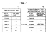
- Fig. 7 respectively shows a differential bit map T4 and saving destination address control table T5 that are used to control the differential data 192. Furthermore, in the second storage device 200 as well, differential data 261 is controlled by the same method as in Fig. 7.
- the differential bit map T4 can be constructed by associating updating flag information indicating the status as to whether or not updating has been performed with each logical track of the disk drives 161 constituting the internal volume 190.
- One logical track corresponds to three cache segments, and has size of 48 kB or 64 kB.
- the saving destination address control table can be constructed by associating with each logical track unit a saving destination address which indicates where the data stored on this track is saved.
- the control units are not limited to track units.
- other control units such as slot units, LBA units or the like can also be used.
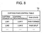
- Fig. 8 is an explanatory diagram which shows one example of the copying pair control table T6.
- the copying pair control table T6 can be constructed by associating information that specifies the copying source LU, information that specifies the copying destination LU and the current pair status. Examples of copying pair status include "pair form (paircreate)", “pair split (pairsplit)", “resynchronize (resync)” and the like.
- the "pair form” status is a state in which initial copying (full copying) from the copying source volume to the copying destination volume has been performed, so that a copying pair is formed.
- the "pair split” status is a state in which the copying source volume and copying destination volume are separated after the copying pair has been forcibly synchronized.
- the "resynchronize” status is a state in which the storage contents of the copying source volume and copying destination volume are resynchronized and a copying pair is formed after the two volumes have been separated.
- Fig. 9 is an explanatory diagram showing one example of the access attribute control table T7.
- the term "access attribute” refers to information that controls the possibility of access to the volumes or the like.
- the access attribute control table T7 can be constructed by associating access attributes with each LU number (LUN).
- access attributes include "read/write possible”, “write prohibited (read only)”, “read/write impossible”, “empty capacity 0”, "copying destination setting impossible” and "hidden”.
- read/write possible indicates a state in which reading and writing from and into the volume in question are possible.
- Writing prohibited indicates a state in which writing into the volume in question is prohibited, so that only read-out is permitted.
- Read/write impossible indicates a state in which writing and reading into and from the volume are prohibited.
- Empty capacity 0 indicates a state in which a response of remaining capacity 0 (full) is given in reply to inquiries regarding the remaining capacity of the volume even in cases where there is actually some remaining capacity.
- Copying destination setting impossible indicates a state in which the volume in question cannot be set as the copying destination volume (secondary volume).
- Hidden indicates a state in which the volume in question cannot be recognized from the initiator.
- the LUNs in the table are numbers used for purposes of description; these numbers in themselves have no particular significance.
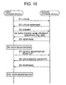
- Fig. 10 is a flow chart illustrating the mapping method that is used in order to utilize the external volume 260 of the second storage device 200 as a virtual internal volume 191 of the first storage device 100. This processing is performed between the first storage device 100 and second storage device 200 when the mapping of the volumes is performed.
- the first storage device 100 logs into the second storage device 200 via the initiator port of the CHA 110 (S1). Logging in is completed by the second storage device 200 sending back a response to the logging in of the first storage device 100 (S2). Next, for example, the first storage device 100 transmits an inquiry command determined by the SCSI (small computer system interface) to the second storage device 200, and requests a response regarding details of the disk drives 220 belonging to the second storage device 200 (S3).
- SCSI small computer system interface
- the inquiry command is used to clarify the type and construction of the inquiry destination device; this makes it possible to pass through the hierarchy of the inquiry destination device and grasp the physical structure of this inquiry destination device.
- the first storage device 100 can acquire information such as the device name, device type, manufacturing serial number (product ID), LDEV number, various types of version information, vendor ID and the like from the second storage device 200 (S4).
- the second storage device 200 responds by transmitting the information for which an inquiry was made to the first storage device 100 (S5).
- the first storage device 100 registers the information acquired from the second storage device 200 in the mapping table T1 (S6).
- the first storage device 100 reads out the storage capacity of the disk drive 220 from the second storage device 200 (S7).
- the second storage device 200 sends back the storage capacity of the disk drive 220 (S8), and returns a response (S9).
- the first storage device 100 registers the storage capacity of the disk drive 220 in a specified place in the mapping table T1 (S10).
- the mapping table T1 can be constructed by performing the above processing. In cases where the input and output of data are performed with the external disk drive 220 (external LUN, i. e., external volume 260) mapped into the V-VOL of the first storage device 100, address conversion and the like are performed with reference to the other conversion tables T2 and T3 described with reference to Fig. 6.
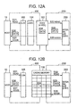
- Fig. 11 is a model diagram which shows the processing that is performed when data is written.
- the host 10 can write data into a logical volume (LDEV) that has access authorization. For example, by using procedures such as zoning that sets a virtual SAN subnet in the SAN or LUN masking in which the host 10 holds a list of accessible LUNs, it is possible to set the host 10 so that the host 10 can access only specified LDEVs.
- LDEV logical volume
- the LDEV into which the host 10 is to write data is connected via a VDEV to a disk drive 161 which is in internal storage device
- data is written by ordinary processing. Specifically, the data from the host 10 is temporarily stored in the cache memory 130, and is then stored in a specified address of a specified disk drive 161 from the cache memory 130 via the DKA 120.
- the DKA 120 converts the logical address into a physical address.
- the same data is stored in a plurality of disk drives 161 or the like.
- Fig. 11 (a) is a flow chart centering on the storage hierarchy
- Fig. 11 (b) is a flow chart centering on the manner of use of the cache memory 130.
- the host 10 indicates an LDEV number that specifies the LDEV that is.the object of writing and a WWN that specifies the communications port that is used to access this LDEV, and issues a write command (write) (S21).
- the first storage device 100 receives a write command from the host 10, the first storage device 100 produces a write command for transmission to the second storage device 200, and transmits this command to the second storage device 200 (S22).
- the first storage device 100 alters the address information and the like contained in the write command received from the host 10 so as to match the external volume 260, thus producing a new write command.
- the host 10 transmits the write data to the to the first storage device 100 (S23).
- the write data received by the first storage device 100 is transferred to the second storage device 200 (S26) from the LDEV via the V-VOL (S24).
- the first storage device 100 sends back a response (good) indicating the completion of writing to the host 10.
- the second storage device 200 transmits a writing completion report to the first storage device 100 (S26). Specifically, the time at which the completion of writing is reported to the host 10 by the first storage device 100 (S25) and the time at which the data is actually stored in the disk drive 220 are different (asynchronous system). Accordingly, the host 10 is released from data write processing before the write data is actually stored in the disk drive 220, so that the host 10 can perform other processing.
- the first storage device 100 converts the logical block addresses designated by the host 10 into sub-block addresses, and stores data in specified locations in the cache memory 130 (S24).
- the V-VOLs and VDEVs have a logical presence installed in the storage space of the cache memory 130.
- the host 10 designates a communications port 111 and transmits a data read-out command to the first storage device 100 (S31).
- the first storage device 100 receives a read command
- the first storage device 100 produces a read command in order to read out the requested data from the second storage device 200.
- the first storage device 100 transmits the produced read command to the second storage device 200 (S32).
- the second storage device 200 reads out the requested data from the disk drive 220, transmits this read-out data to the first storage device 100 (S33), and reports that read-out was normally completed (S35).
- the first storage device 100 stores the data received from the second storage device 200 in a specified location in the cache memory 130 (S34).
- the first storage device 100 reads out the data stored in the cache memory 130, performs address conversion, transmits the data to the host 10 via the LUN 103 or the like (S36), and issues a read-out completion report (S37). In the series of processing performed in these data read-outs, the conversion operation described with reference to Fig. 6 is performed in reverse.
- Fig. 12 the operation is shown as if data is read out from the second storage device 200 and stored in the cache memory 130 in accordance with the request from the host 10.
- the operation is not limited to this; it would also be possible to store all or part of the data stored in the external volume 260 in the cache memory 130 beforehand. In this case, in response to a command from the host 10, data can be immediately read out from the cache memory 130 and transmitted to the host 10.
- Figs. 13 and 14 show the full copying mode in which all of the storage contents of the copying source volume are copied into the copying destination volume
- Figs. 15 and 16 show the differential copying mode in which only the differential data generated in the copying source volume following the completion of full copying is coped into the copying destination volume. In the case of both copying modes, data is transferred directly between the first storage device and second storage device; the host 10 does not participate.
- the managing device 20 instructs the first storage device 100 to execute the first full copying mode (S41).
- the CHA 110 that receives this instruction refers to the mapping table T1 stored in the shared memory 140 (S42), and acquires path information for the external volume 260 which is the copying destination volume.
- the CHA 110 issues a read command to the second storage device 200 (S43), and requests the read-out of the data that is stored in the external volume 260.
- the second storage device 200 In response to the read command from the first storage device 100, the second storage device 200 reads out data from the external volume 260 (S44), and transmits this read-out data to the first storage device 100 (S45).
- the CHA 110 When the CHA 110 receives the data from the second storage device 200, the CHA 110 stores this received data in the cache memory 130 (S46). Furthermore, for example, the CHA 110 requests the execution of destage processing from the DKA 120 by writing a write command into shared memory 140 (S47).
- the DKA 120 occasionally refers to the shared memory 140, and when the DKA 120 discovers an unprocessed write command, the DKA 120 reads out the data stored in the cache memory 130, performs processing such as address conversion and the like, and writes this data into a specified disk drive 161 (S48).
- Fig. 14 shows the processing of the second full copying mode.
- the first storage device 100 instructs the first storage device 100 to execute the second full copying mode (S51).
- the CHA 110 that receives this instruction refers to the mapping table T1 stored in the shared memory 140 (S52), and acquires path information for the external volume 260 which is the copying destination volume. Furthermore, the CHA 110 requests that the DKA 120 perform staging (processing that transfers the data to a cache) of the data stored in the internal volume 190 (S53).
- the DKA 120 reads out the data of the internal volume 190 from the disk drive 161, and stores this data in the cache memory 130 (S54). Furthermore, the DKA 120 request that the CHA 110 issue a write command (S55).
- the CHA 110 issues a write command to the second storage device 200 (S56).
- the CHA 110 transmits write data to the second storage device 200 (S57).
- the second storage device 200 receives the write data from the first storage device 100 (S58), and stores this data in a specified disk drive 220 (S59).
- the storage contents of the internal volume 190 which is the copying source volume can be copied into the external volume 260 which is the copying destination volume, so that the storage contents of both volumes can be caused to coincide.
- Fig. 15 shows the processing of the first differential copying mode.
- the managing device 20 requests the first storage device 100 to split the copying pair (S61).
- the CHA 110 that receives the splitting instruction updates the copying pair control table T6 stored in the shared memory 140, and alters the status of the copying pair to a split state (S62).
- the pair state of the internal volume 190 and virtual internal volume 191 is dissolved.
- the host 10A executes updating I/O for the internal volume 190 (S63).
- the CHA 110 stores the write data received from the host 10A in the cache memory 130 (S64), and sends a response to the host 10A indicating that processing of the write command has been completed (S65)
- the CHA 110 respectively updates the differential bit map T4 and the differential data 192 (S66), and requests that the DKA 120 execute destage processing (S67).
- the DKA 120 stores the write data generated by the updating I/O in the disk drive 161 (S68).
- the updating I/O from the host 10A is stopped (S69). For example, this stopping of the I/O can be accomplished manually by the user. Furthermore, the managing device 20 alters the access attribute of the internal volume 190 from "read/write possible" to "write prohibited” (S70). Although the issuing of updating I/O by the host 10A is already stopped, further variation of the storage contents of the internal volume 190 can be prevented in advance by altering the access attribute to "write prohibited".
- the managing device 20 instructs the first storage device 100 to execute first differential copying (S71).
- the CHA 110 that receives this instruction refers to the mapping table T1 (S72), and acquires path information for the external volume 260. Furthermore, the CHA 110 refers to the differential bit map T4 (S73), and requests that the DKA 120 perform destaging of the differential data 192 (S74).
- the DKA 120 reads out the differential data 192 produced for the internal volume 190 from the disk drive 161, and stores this data in the cache memory 130 (S75). Then, the DKA 120 requests that the CHA 110 issue a write command (S76).
- the CHA 110 issues a write command to the second storage device 200 (S77), and transmits write data (the differential data 192) to the second storage device 200 (S78).
- the second storage device 200 stores the received write data in the external volume 260.
- the storage contents of the external volume 260 and internal volume 190 coincide.
- the managing device 20 alters the access attribute of the internal volume 190 from "write prohibited" to "read/write possible” (S79).
- Fig. 16 shows the processing of the second differential copying mode.
- the managing device 20 first instructs the first storage device 100 to split the copying pair (S81).
- the CHA 110 that receives this instruction updates the copying pair control table T6, and dissolves the pair state (S82).
- the second storage device 200 writes the write data into the disk drive 220 (S84), and respectively updates the differential data 261 and differential bit map T4 (2) (S85).
- the managing device 20 alters the access attribute of the external volume 260 from "read/write possible" to "write prohibited” (S86), thus prohibiting updating of the external volume 260; then, the managing device 20 instructs the first storage device 100 to initiate second differential copying (S87).
- the CHA 110 that receives the instruction to initiate differential copying requests that the second storage device 200 to transfer the differential bit map T4 (2) (S88). Since the contacts of the differential data 261 generated in the external volume 260 are controlled by the second storage device 200, the first storage device 100 acquires the differential bit map T4 (2) from the second storage device 200 (S89) .
- a construction is used in which commands and data are directly exchanged between the first storage device 100 and second storage device 200.
- the present invention is not limited to this; for example, it would also be possible to exchange data such as the differential bit map and the like between the respective storage devices 100 and 200 via the managing device 20.
- the CHA 110 refers to the mapping table T1 (S90), and acquires path information indicating the path to the external volume 260. Then, the CHA 110 requests the transfer of the differential data 261 by issuing a read command to the second storage device 200 (S91).
- the second storage device 200 transmits the differential data 261 to the first storage device 100 (S92). Then, the CHA 110 that receives this differential data 261 stores the differential data 261 in the cache memory 130 (S93). The CHA 110 requests that the DKA 120 perform destage processing of the differential data 261 (S94). Then, the DKA 120 reads out the differential data 261 stored in the cache memory 130, and writes the data constituting the internal volume 190 into the disk drive 161 (S95). As a result, the storage contents of the external volume 260 and internal volume 190 coincide.
- the external volume 260 can be handled as though this volume were a logical volume inside the first storage device 100 by mapping the external disk drive 220 into the V-VOL. Accordingly, even in cases where the second storage device 200 is an old type device that cannot be directly connected to the host 10, the memory resources of the old type device can be reutilized as memory resources of the first storage device 100, and can be provided to the host 10, by interposing a new type first storage device 100. As a result, the old type storage device 200 can be connected to a new type storage device 100, and the memory resources can be effectively utilized.
- the low performance of the second storage device can be hidden by the high-performance computer resources (cache capacity, CPU processing speed and the like) of the first storage device 100, so that high-performance services can be provided to the host 10 using a virtual internal volume that utilizes the disk drive 220.
- functions such as (for example) striping, expansion, splitting, RAID and the like can be added to an external volume 260 constructed in the disk drive 220, and can be used. Accordingly, compared to cases in which an external volume is directly mapped into an LUN, the degree of freedom of utilization is increased so that convenience of use is improved.
- the storage contents can be synchronized between the internal volume 190 and virtual internal volume 191 (external volume 260). Accordingly, a backup of the internal volume 190 can be formed in the virtual internal volume 191, or conversely, a backup of the virtual internal volume 191 can be formed in the internal volume 190, so that the convenience is even further improved.
- FIG. 17 is an explanatory diagram showing the storage structure of a storage system constituting a second embodiment of the present invention.
- the first storage device 100 comprises a third storage device 300 in addition to a second storage device 200.
- this third storage device 300 is a device that is externally connected to the first storage device 100.
- the third storage device 300 comprises (for example) PDEVs 320, VDEVs 330, LDEVs 349, LUs 350, targets 311 and the like.
- the construction of the third storage device 300 the construction of the second storage device 200 can be employed; since this construction is not the gist of the present invention, details will be omitted.
- the second storage device 200 and third storage device 300 need not have the same structure.
- the first storage device 100 does not comprise PDEVs 161 which are physical storage devices, and does not comprise real volumes (internal volumes).
- the first storage device 100 comprises only "LDEV 1" and "LDEV 2", which are virtual internal volumes. Accordingly, the first storage device 100 need not be a disk array device; for example, this first storage device 100 may be an intelligent type switch comprises a computer system.
- the first virtual internal volume “LDEV 1" 164 is connected to "LDEV 1" 240, which is a real volume of the second storage device 200, via "V-VOL” 163.
- the second virtual internal volume “LDEV 2" 164 is connected to "LDEV 1" 340, which is a real volume of the third storage device 300, via "V-VOL 2" 163.
- the system is devised so that full copying and differential copying are performed between the first virtual internal volume "LDEV 1" and the second virtual internal volume "LDEV 2" inside the first storage device 100.
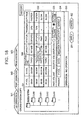
- FIG. 18 is an explanatory diagram which shows one example of the control screen used by the storage system. This embodiment can be used in any of the respective embodiments described above.
- the user logs into the managing device 20, and calls up a control screen such as that shown in Fig. 18.
- the managing device 20 sends instructions for alteration of the construction to one or both of the storage devices 100 and 200. Receiving these instructions, the respective storage devices 100 and 200 alter their internal construction.
- control menus M1 through M3 can be set on the control screen.
- these control menus M1 through M3 can be constructed as tab type switching menus.
- the menu M1 is a menu that is used to perform various types of LU operations such as production of volumes or the like.
- the menu M2 is a menu that is used to perform communications port operations.
- the menu M3 is a menu that is used to perform volume copying operations between the storage devices described in the abovementioned embodiments,
- the menu M3 can be constructed so that this menu includes a plurality of screen regions G1 through G5.
- the screen region G1 is used to select the storage device (subsystem) that performs the setting of copying pairs.
- the conditions of the set copying pairs are displayed in the screen region G2.
- the copying source volume (P-VOL), copying destination volume (S-VOL), emulation type, capacity, copying status, progression, copying speed and the like can be displayed in the screen region G2.
- the user can select two copying pairs displayed in the screen region G2; furthermore, the user can display the submenu M4 by right clicking [with the mouse].
- the user can designate the synchronization of volumes or dissolution of pairs by means of the submenu M4.
- either internal volumes inside the first storage device 100 or external volumes inside the second storage device 200 can be exclusively selected as the volumes of the copying pair.
- an internal volume is selected as the copying source volume.
- An internal volume or external volume can be designated as either the copying source volume or copying destination volume.
- Preset values can be displayed in the screen region G4.
- Operation states can be displayed in the screen region G5.
- the user can cause alterations in the construction to be reflected by operating an application button B1.
- the user operates a cancel button B2.
- the abovementioned screen construction is an example; the present invention is not limited to this construction.
Landscapes
- Engineering & Computer Science (AREA)
- Theoretical Computer Science (AREA)
- Physics & Mathematics (AREA)
- General Engineering & Computer Science (AREA)
- General Physics & Mathematics (AREA)
- Human Computer Interaction (AREA)
- Quality & Reliability (AREA)
- Information Retrieval, Db Structures And Fs Structures Therefor (AREA)
Applications Claiming Priority (2)
| Application Number | Priority Date | Filing Date | Title |
|---|---|---|---|
| JP2004312358A JP2006127028A (ja) | 2004-10-27 | 2004-10-27 | 記憶システム及び記憶制御装置 |
| EP05253410A EP1657631A1 (de) | 2004-10-27 | 2005-06-02 | Speichersystem und Speichersteuerungsvorrichtung |
Related Parent Applications (1)
| Application Number | Title | Priority Date | Filing Date |
|---|---|---|---|
| EP05253410A Division EP1657631A1 (de) | 2004-10-27 | 2005-06-02 | Speichersystem und Speichersteuerungsvorrichtung |
Publications (2)
| Publication Number | Publication Date |
|---|---|
| EP1777616A2 true EP1777616A2 (de) | 2007-04-25 |
| EP1777616A3 EP1777616A3 (de) | 2007-07-25 |
Family
ID=34941557
Family Applications (2)
| Application Number | Title | Priority Date | Filing Date |
|---|---|---|---|
| EP05253410A Ceased EP1657631A1 (de) | 2004-10-27 | 2005-06-02 | Speichersystem und Speichersteuerungsvorrichtung |
| EP07001832A Withdrawn EP1777616A3 (de) | 2004-10-27 | 2005-06-02 | Speichersystem und Speichersteuerungsvorrichtung |
Family Applications Before (1)
| Application Number | Title | Priority Date | Filing Date |
|---|---|---|---|
| EP05253410A Ceased EP1657631A1 (de) | 2004-10-27 | 2005-06-02 | Speichersystem und Speichersteuerungsvorrichtung |
Country Status (3)
| Country | Link |
|---|---|
| US (3) | US20060090048A1 (de) |
| EP (2) | EP1657631A1 (de) |
| JP (1) | JP2006127028A (de) |
Families Citing this family (50)
| Publication number | Priority date | Publication date | Assignee | Title |
|---|---|---|---|---|
| JP2006127028A (ja) * | 2004-10-27 | 2006-05-18 | Hitachi Ltd | 記憶システム及び記憶制御装置 |
| US7130960B1 (en) * | 2005-04-21 | 2006-10-31 | Hitachi, Ltd. | System and method for managing disk space in a thin-provisioned storage subsystem |
| JP4741304B2 (ja) * | 2005-07-11 | 2011-08-03 | 株式会社日立製作所 | データマイグレーション方法又はデータマイグレーションシステム |
| US7165158B1 (en) * | 2005-08-17 | 2007-01-16 | Hitachi, Ltd. | System and method for migrating a replication system |
| JP5222469B2 (ja) * | 2006-10-11 | 2013-06-26 | 株式会社日立製作所 | 記憶システム及びデータ管理方法 |
| JP2008108145A (ja) * | 2006-10-26 | 2008-05-08 | Hitachi Ltd | 計算機システム及びこれを用いたデータの管理方法 |
| US8949383B1 (en) * | 2006-11-21 | 2015-02-03 | Cisco Technology, Inc. | Volume hierarchy download in a storage area network |
| JP5031341B2 (ja) * | 2006-11-30 | 2012-09-19 | 株式会社日立製作所 | 記憶システム及びデータ管理方法 |
| JP2010512584A (ja) | 2006-12-06 | 2010-04-22 | フュージョン マルチシステムズ,インク.(ディービイエイ フュージョン−アイオー) | 空データトークン指令を有する要求デバイスからのデータを管理する装置、システムおよび方法 |
| US8489817B2 (en) | 2007-12-06 | 2013-07-16 | Fusion-Io, Inc. | Apparatus, system, and method for caching data |
| US8443134B2 (en) | 2006-12-06 | 2013-05-14 | Fusion-Io, Inc. | Apparatus, system, and method for graceful cache device degradation |
| US9104599B2 (en) | 2007-12-06 | 2015-08-11 | Intelligent Intellectual Property Holdings 2 Llc | Apparatus, system, and method for destaging cached data |
| US8706968B2 (en) | 2007-12-06 | 2014-04-22 | Fusion-Io, Inc. | Apparatus, system, and method for redundant write caching |
| JP4961997B2 (ja) * | 2006-12-22 | 2012-06-27 | 富士通株式会社 | ストレージ装置、ストレージ装置の制御方法、及びストレージ装置の制御プログラム |
| JP5142629B2 (ja) | 2007-08-22 | 2013-02-13 | 株式会社日立製作所 | 仮想ボリュームのバックアップを行うストレージシステム及び方法 |
| JP2009088739A (ja) * | 2007-09-28 | 2009-04-23 | Hitachi Ltd | データ転送装置 |
| US9519540B2 (en) | 2007-12-06 | 2016-12-13 | Sandisk Technologies Llc | Apparatus, system, and method for destaging cached data |
| US7836226B2 (en) | 2007-12-06 | 2010-11-16 | Fusion-Io, Inc. | Apparatus, system, and method for coordinating storage requests in a multi-processor/multi-thread environment |
| JP2009163542A (ja) * | 2008-01-08 | 2009-07-23 | Hitachi Ltd | 論理ボリュームに関する設定を制御する制御装置 |
| JP2009205333A (ja) * | 2008-02-27 | 2009-09-10 | Hitachi Ltd | 計算機システム、ストレージ装置及びデータ管理方法 |
| JP5317495B2 (ja) | 2008-02-27 | 2013-10-16 | 株式会社日立製作所 | ストレージシステム、コピー方法及び正側のストレージ装置 |
| JP4576449B2 (ja) * | 2008-08-29 | 2010-11-10 | 富士通株式会社 | スイッチ装置およびコピー制御方法 |
| JP5138530B2 (ja) * | 2008-10-08 | 2013-02-06 | 株式会社日立製作所 | ストレージ容量仮想化技術における障害管理方式 |
| US8396835B2 (en) * | 2009-05-25 | 2013-03-12 | Hitachi, Ltd. | Computer system and its data control method |
| JP2011008548A (ja) | 2009-06-25 | 2011-01-13 | Fujitsu Ltd | データ中継装置およびストレージシステム |
| WO2011024221A1 (en) * | 2009-08-26 | 2011-03-03 | Hitachi,Ltd. | Remote copy system |
| CN102696010B (zh) | 2009-09-08 | 2016-03-23 | 才智知识产权控股公司(2) | 用于将数据高速缓存在固态存储设备上的装置、系统和方法 |
| WO2012106362A2 (en) | 2011-01-31 | 2012-08-09 | Fusion-Io, Inc. | Apparatus, system, and method for managing eviction of data |
| US9003104B2 (en) | 2011-02-15 | 2015-04-07 | Intelligent Intellectual Property Holdings 2 Llc | Systems and methods for a file-level cache |
| US9201677B2 (en) | 2011-05-23 | 2015-12-01 | Intelligent Intellectual Property Holdings 2 Llc | Managing data input/output operations |
| US8874823B2 (en) | 2011-02-15 | 2014-10-28 | Intellectual Property Holdings 2 Llc | Systems and methods for managing data input/output operations |
| WO2012116369A2 (en) | 2011-02-25 | 2012-08-30 | Fusion-Io, Inc. | Apparatus, system, and method for managing contents of a cache |
| US8301812B1 (en) * | 2011-03-24 | 2012-10-30 | Emc Corporation | Techniques for performing host path detection verification |
| US8751762B2 (en) * | 2011-03-30 | 2014-06-10 | International Business Machines Corporation | Prevention of overlay of production data by point in time copy operations in a host based asynchronous mirroring environment |
| JP5439435B2 (ja) | 2011-06-14 | 2014-03-12 | 株式会社日立製作所 | 計算機システムおよびその計算機システムにおけるディスク共有方法 |
| US8965856B2 (en) * | 2011-08-29 | 2015-02-24 | Hitachi, Ltd. | Increase in deduplication efficiency for hierarchical storage system |
| US10102117B2 (en) | 2012-01-12 | 2018-10-16 | Sandisk Technologies Llc | Systems and methods for cache and storage device coordination |
| US9251052B2 (en) | 2012-01-12 | 2016-02-02 | Intelligent Intellectual Property Holdings 2 Llc | Systems and methods for profiling a non-volatile cache having a logical-to-physical translation layer |
| US9767032B2 (en) | 2012-01-12 | 2017-09-19 | Sandisk Technologies Llc | Systems and methods for cache endurance |
| US9251086B2 (en) | 2012-01-24 | 2016-02-02 | SanDisk Technologies, Inc. | Apparatus, system, and method for managing a cache |
| US9116812B2 (en) | 2012-01-27 | 2015-08-25 | Intelligent Intellectual Property Holdings 2 Llc | Systems and methods for a de-duplication cache |
| US10019353B2 (en) | 2012-03-02 | 2018-07-10 | Longitude Enterprise Flash S.A.R.L. | Systems and methods for referencing data on a storage medium |
| JP5942511B2 (ja) * | 2012-03-19 | 2016-06-29 | 富士通株式会社 | バックアップ装置,バックアップ方法,およびバックアッププログラム |
| US9612966B2 (en) | 2012-07-03 | 2017-04-04 | Sandisk Technologies Llc | Systems, methods and apparatus for a virtual machine cache |
| US10339056B2 (en) | 2012-07-03 | 2019-07-02 | Sandisk Technologies Llc | Systems, methods and apparatus for cache transfers |
| US10346095B2 (en) | 2012-08-31 | 2019-07-09 | Sandisk Technologies, Llc | Systems, methods, and interfaces for adaptive cache persistence |
| US9842053B2 (en) | 2013-03-15 | 2017-12-12 | Sandisk Technologies Llc | Systems and methods for persistent cache logging |
| WO2014141462A1 (ja) * | 2013-03-15 | 2014-09-18 | 株式会社日立製作所 | 計算機切替方法、計算機システム、及び管理計算機 |
| GB2516435A (en) | 2013-04-05 | 2015-01-28 | Continental Automotive Systems | Embedded memory management scheme for real-time applications |
| KR102728659B1 (ko) * | 2018-09-21 | 2024-11-12 | 에스케이하이닉스 주식회사 | 내부채널을 통해 서로 간에 연결된 다수의 메모리 시스템을 포함하는 데이터 처리 시스템 |
Family Cites Families (215)
| Publication number | Priority date | Publication date | Assignee | Title |
|---|---|---|---|---|
| US3771137A (en) | 1971-09-10 | 1973-11-06 | Ibm | Memory control in a multipurpose system utilizing a broadcast |
| US4025904A (en) * | 1973-10-19 | 1977-05-24 | Texas Instruments Incorporated | Programmed allocation of computer memory workspace |
| USRE37305E1 (en) | 1982-12-30 | 2001-07-31 | International Business Machines Corporation | Virtual memory address translation mechanism with controlled data persistence |
| US4710868A (en) | 1984-06-29 | 1987-12-01 | International Business Machines Corporation | Interconnect scheme for shared memory local networks |
| US5170480A (en) | 1989-09-25 | 1992-12-08 | International Business Machines Corporation | Concurrently applying redo records to backup database in a log sequence using single queue server per queue at a time |
| US5307481A (en) * | 1990-02-28 | 1994-04-26 | Hitachi, Ltd. | Highly reliable online system |
| US5155845A (en) | 1990-06-15 | 1992-10-13 | Storage Technology Corporation | Data storage system for providing redundant copies of data on different disk drives |
| US5544347A (en) | 1990-09-24 | 1996-08-06 | Emc Corporation | Data storage system controlled remote data mirroring with respectively maintained data indices |
| US5459857A (en) | 1992-05-15 | 1995-10-17 | Storage Technology Corporation | Fault tolerant disk array data storage subsystem |
| US5555371A (en) | 1992-12-17 | 1996-09-10 | International Business Machines Corporation | Data backup copying with delayed directory updating and reduced numbers of DASD accesses at a back up site using a log structured array data storage |
| US5408465A (en) * | 1993-06-21 | 1995-04-18 | Hewlett-Packard Company | Flexible scheme for admission control of multimedia streams on integrated networks |
| KR0128271B1 (ko) * | 1994-02-22 | 1998-04-15 | 윌리암 티. 엘리스 | 재해회복을 위한 일관성 그룹 형성방법 및 레코드갱싱의 섀도잉 방법, 주시스템, 원격데이타 섀도잉 시스템과 비동기 원격데이타 복제 시스템 |
| US5574950A (en) | 1994-03-01 | 1996-11-12 | International Business Machines Corporation | Remote data shadowing using a multimode interface to dynamically reconfigure control link-level and communication link-level |
| US5504882A (en) * | 1994-06-20 | 1996-04-02 | International Business Machines Corporation | Fault tolerant data storage subsystem employing hierarchically arranged controllers |
| US5835953A (en) | 1994-10-13 | 1998-11-10 | Vinca Corporation | Backup system that takes a snapshot of the locations in a mass storage device that has been identified for updating prior to updating |
| US5548712A (en) | 1995-01-19 | 1996-08-20 | Hewlett-Packard Company | Data storage system and method for managing asynchronous attachment and detachment of storage disks |
| US5799323A (en) | 1995-01-24 | 1998-08-25 | Tandem Computers, Inc. | Remote duplicate databased facility with triple contingency protection |
| US5680580A (en) | 1995-02-28 | 1997-10-21 | International Business Machines Corporation | Remote copy system for setting request interconnect bit in each adapter within storage controller and initiating request connect frame in response to the setting bit |
| US5917723A (en) * | 1995-05-22 | 1999-06-29 | Lsi Logic Corporation | Method and apparatus for transferring data between two devices with reduced microprocessor overhead |
| US5799141A (en) | 1995-06-09 | 1998-08-25 | Qualix Group, Inc. | Real-time data protection system and method |
| US5720029A (en) * | 1995-07-25 | 1998-02-17 | International Business Machines Corporation | Asynchronously shadowing record updates in a remote copy session using track arrays |
| US5680640A (en) | 1995-09-01 | 1997-10-21 | Emc Corporation | System for migrating data by selecting a first or second transfer means based on the status of a data element map initialized to a predetermined state |
| US5819020A (en) | 1995-10-16 | 1998-10-06 | Network Specialists, Inc. | Real time backup system |
| US5758118A (en) * | 1995-12-08 | 1998-05-26 | International Business Machines Corporation | Methods and data storage devices for RAID expansion by on-line addition of new DASDs |
| US5809285A (en) | 1995-12-21 | 1998-09-15 | Compaq Computer Corporation | Computer system having a virtual drive array controller |
| JP3287203B2 (ja) | 1996-01-10 | 2002-06-04 | 株式会社日立製作所 | 外部記憶制御装置及び外部記憶制御装置間データ転送方法 |
| US5870537A (en) * | 1996-03-13 | 1999-02-09 | International Business Machines Corporation | Concurrent switch to shadowed device for storage controller and device errors |
| JP3641872B2 (ja) | 1996-04-08 | 2005-04-27 | 株式会社日立製作所 | 記憶装置システム |
| GB2312319B (en) | 1996-04-15 | 1998-12-09 | Discreet Logic Inc | Video storage |
| US5901327A (en) * | 1996-05-28 | 1999-05-04 | Emc Corporation | Bundling of write data from channel commands in a command chain for transmission over a data link between data storage systems for remote data mirroring |
| US6477627B1 (en) | 1996-05-31 | 2002-11-05 | Emc Corporation | Method and apparatus for mirroring data in a remote data storage system |
| US6092066A (en) | 1996-05-31 | 2000-07-18 | Emc Corporation | Method and apparatus for independent operation of a remote data facility |
| US5933653A (en) | 1996-05-31 | 1999-08-03 | Emc Corporation | Method and apparatus for mirroring data in a remote data storage system |
| US6101497A (en) | 1996-05-31 | 2000-08-08 | Emc Corporation | Method and apparatus for independent and simultaneous access to a common data set |
| US5995980A (en) | 1996-07-23 | 1999-11-30 | Olson; Jack E. | System and method for database update replication |
| US5835954A (en) | 1996-09-12 | 1998-11-10 | International Business Machines Corporation | Target DASD controlled data migration move |
| JP3193880B2 (ja) * | 1996-12-11 | 2001-07-30 | 株式会社日立製作所 | データ移行方法 |
| JP3410010B2 (ja) | 1997-12-24 | 2003-05-26 | 株式会社日立製作所 | サブシステムの移行方法および情報処理システム |
| US6583797B1 (en) * | 1997-01-21 | 2003-06-24 | International Business Machines Corporation | Menu management mechanism that displays menu items based on multiple heuristic factors |
| US5895485A (en) * | 1997-02-24 | 1999-04-20 | Eccs, Inc. | Method and device using a redundant cache for preventing the loss of dirty data |
| US5895495A (en) * | 1997-03-13 | 1999-04-20 | International Business Machines Corporation | Demand-based larx-reserve protocol for SMP system buses |
| US6073209A (en) | 1997-03-31 | 2000-06-06 | Ark Research Corporation | Data storage controller providing multiple hosts with access to multiple storage subsystems |
| JP3671595B2 (ja) * | 1997-04-01 | 2005-07-13 | 株式会社日立製作所 | 複合計算機システムおよび複合i/oシステム |
| JP3228182B2 (ja) * | 1997-05-29 | 2001-11-12 | 株式会社日立製作所 | 記憶システム及び記憶システムへのアクセス方法 |
| US6012123A (en) * | 1997-06-10 | 2000-01-04 | Adaptec Inc | External I/O controller system for an independent access parity disk array |
| JP3414218B2 (ja) * | 1997-09-12 | 2003-06-09 | 株式会社日立製作所 | 記憶制御装置 |
| US6052758A (en) * | 1997-12-22 | 2000-04-18 | International Business Machines Corporation | Interface error detection and isolation in a direct access storage device DASD system |
| US6247103B1 (en) * | 1998-01-06 | 2001-06-12 | International Business Machines Corporation | Host storage management control of outboard data movement using push-pull operations |
| US6230246B1 (en) * | 1998-01-30 | 2001-05-08 | Compaq Computer Corporation | Non-intrusive crash consistent copying in distributed storage systems without client cooperation |
| US6173374B1 (en) * | 1998-02-11 | 2001-01-09 | Lsi Logic Corporation | System and method for peer-to-peer accelerated I/O shipping between host bus adapters in clustered computer network |
| JPH11242566A (ja) * | 1998-02-26 | 1999-09-07 | Hitachi Ltd | 多重化データ記憶システム |
| US6324654B1 (en) | 1998-03-30 | 2001-11-27 | Legato Systems, Inc. | Computer network remote data mirroring system |
| US6157991A (en) | 1998-04-01 | 2000-12-05 | Emc Corporation | Method and apparatus for asynchronously updating a mirror of a source device |
| US6070224A (en) * | 1998-04-02 | 2000-05-30 | Emc Corporation | Virtual tape system |
| US6178427B1 (en) * | 1998-05-07 | 2001-01-23 | Platinum Technology Ip, Inc. | Method of mirroring log datasets using both log file data and live log data including gaps between the two data logs |
| US6421711B1 (en) * | 1998-06-29 | 2002-07-16 | Emc Corporation | Virtual ports for data transferring of a data storage system |
| US6260120B1 (en) | 1998-06-29 | 2001-07-10 | Emc Corporation | Storage mapping and partitioning among multiple host processors in the presence of login state changes and host controller replacement |
| US6148383A (en) | 1998-07-09 | 2000-11-14 | International Business Machines Corporation | Storage system employing universal timer for peer-to-peer asynchronous maintenance of consistent mirrored storage |
| US6237008B1 (en) * | 1998-07-20 | 2001-05-22 | International Business Machines Corporation | System and method for enabling pair-pair remote copy storage volumes to mirror data in another storage volume |
| US6253295B1 (en) * | 1998-07-20 | 2001-06-26 | International Business Machines Corporation | System and method for enabling pair-pair remote copy storage volumes to mirror data in another pair of storage volumes |
| US6195730B1 (en) * | 1998-07-24 | 2001-02-27 | Storage Technology Corporation | Computer system with storage device mapping input/output processor |
| DE69938378T2 (de) * | 1998-08-20 | 2009-04-30 | Hitachi, Ltd. | Kopieren von Daten in Speichersystemen |
| SE515084C2 (sv) | 1998-08-26 | 2001-06-05 | Ericsson Telefon Ab L M | Förfarande och anordning i ett IP-nät |
| JP4689137B2 (ja) * | 2001-08-08 | 2011-05-25 | 株式会社日立製作所 | リモートコピー制御方法、及びストレージシステム |
| JP2000099277A (ja) * | 1998-09-18 | 2000-04-07 | Fujitsu Ltd | ファイルユニット間のリモート転送方法 |
| JP4412685B2 (ja) | 1998-09-28 | 2010-02-10 | 株式会社日立製作所 | 記憶制御装置及びこれを用いたデータ格納システムの取り扱い方法 |
| JP2000163329A (ja) | 1998-11-27 | 2000-06-16 | Nec Corp | データ転送システム |
| US6718457B2 (en) * | 1998-12-03 | 2004-04-06 | Sun Microsystems, Inc. | Multiple-thread processor for threaded software applications |
| JP2000242434A (ja) | 1998-12-22 | 2000-09-08 | Hitachi Ltd | 記憶装置システム |
| US6542961B1 (en) | 1998-12-22 | 2003-04-01 | Hitachi, Ltd. | Disk storage system including a switch |
| US6457139B1 (en) | 1998-12-30 | 2002-09-24 | Emc Corporation | Method and apparatus for providing a host computer with information relating to the mapping of logical volumes within an intelligent storage system |
| US7107395B1 (en) * | 1998-12-31 | 2006-09-12 | Emc Corporation | Apparatus and methods for operating a computer storage system |
| US6209002B1 (en) * | 1999-02-17 | 2001-03-27 | Emc Corporation | Method and apparatus for cascading data through redundant data storage units |
| US6397307B2 (en) * | 1999-02-23 | 2002-05-28 | Legato Systems, Inc. | Method and system for mirroring and archiving mass storage |
| US6453354B1 (en) | 1999-03-03 | 2002-09-17 | Emc Corporation | File server system using connection-oriented protocol and sharing data sets among data movers |
| US6370605B1 (en) | 1999-03-04 | 2002-04-09 | Sun Microsystems, Inc. | Switch based scalable performance storage architecture |
| JP3780732B2 (ja) | 1999-03-10 | 2006-05-31 | 株式会社日立製作所 | 分散制御システム |
| US6553408B1 (en) * | 1999-03-25 | 2003-04-22 | Dell Products L.P. | Virtual device architecture having memory for storing lists of driver modules |
| US6654830B1 (en) | 1999-03-25 | 2003-11-25 | Dell Products L.P. | Method and system for managing data migration for a storage system |
| US6640278B1 (en) | 1999-03-25 | 2003-10-28 | Dell Products L.P. | Method for configuration and management of storage resources in a storage network |
| US6446141B1 (en) | 1999-03-25 | 2002-09-03 | Dell Products, L.P. | Storage server system including ranking of data source |
| JP2000276304A (ja) | 1999-03-26 | 2000-10-06 | Nec Corp | データ移行方法と情報処理システム |
| JP3764016B2 (ja) * | 1999-05-10 | 2006-04-05 | 財団法人流通システム開発センタ− | 統合ip転送網 |
| US6247099B1 (en) * | 1999-06-03 | 2001-06-12 | International Business Machines Corporation | System and method for maintaining cache coherency and data synchronization in a computer system having multiple active controllers |
| US6219753B1 (en) * | 1999-06-04 | 2001-04-17 | International Business Machines Corporation | Fiber channel topological structure and method including structure and method for raid devices and controllers |
| US6697387B1 (en) * | 1999-06-07 | 2004-02-24 | Micron Technology, Inc. | Apparatus for multiplexing signals through I/O pins |
| US6662197B1 (en) | 1999-06-25 | 2003-12-09 | Emc Corporation | Method and apparatus for monitoring update activity in a data storage facility |
| JP3853540B2 (ja) | 1999-06-30 | 2006-12-06 | 日本電気株式会社 | ファイバチャネル接続磁気ディスク装置およびファイバチャネル接続磁気ディスク制御装置 |
| US6446175B1 (en) | 1999-07-28 | 2002-09-03 | Storage Technology Corporation | Storing and retrieving data on tape backup system located at remote storage system site |
| JP3541744B2 (ja) | 1999-08-30 | 2004-07-14 | 株式会社日立製作所 | ストレージサブシステム及びその制御方法 |
| US6804676B1 (en) | 1999-08-31 | 2004-10-12 | International Business Machines Corporation | System and method in a data processing system for generating compressed affinity records from data records |
| US6463501B1 (en) | 1999-10-21 | 2002-10-08 | International Business Machines Corporation | Method, system and program for maintaining data consistency among updates across groups of storage areas using update times |
| US6338126B1 (en) * | 1999-12-06 | 2002-01-08 | Legato Systems, Inc. | Crash recovery without complete remirror |
| US6625623B1 (en) | 1999-12-16 | 2003-09-23 | Livevault Corporation | Systems and methods for backing up data files |
| US6526418B1 (en) * | 1999-12-16 | 2003-02-25 | Livevault Corporation | Systems and methods for backing up data files |
| US6460055B1 (en) | 1999-12-16 | 2002-10-01 | Livevault Corporation | Systems and methods for backing up data files |
| US6484173B1 (en) | 2000-02-07 | 2002-11-19 | Emc Corporation | Controlling access to a storage device |
| US20020103889A1 (en) | 2000-02-11 | 2002-08-01 | Thomas Markson | Virtual storage layer approach for dynamically associating computer storage with processing hosts |
| JP3866894B2 (ja) * | 2000-02-29 | 2007-01-10 | 東芝プラントシステム株式会社 | プラスチックの熱分解方法およびこの方法により得られた熱分解生成物 |
| US20020065864A1 (en) * | 2000-03-03 | 2002-05-30 | Hartsell Neal D. | Systems and method for resource tracking in information management environments |
| JP3918394B2 (ja) | 2000-03-03 | 2007-05-23 | 株式会社日立製作所 | データ移行方法 |
| US6487645B1 (en) | 2000-03-06 | 2002-11-26 | International Business Machines Corporation | Data storage subsystem with fairness-driven update blocking |
| US6654831B1 (en) | 2000-03-07 | 2003-11-25 | International Business Machine Corporation | Using multiple controllers together to create data spans |
| US6446176B1 (en) | 2000-03-09 | 2002-09-03 | Storage Technology Corporation | Method and system for transferring data between primary storage and secondary storage using a bridge volume and an internal snapshot copy of the data being transferred |
| US6490659B1 (en) | 2000-03-31 | 2002-12-03 | International Business Machines Corporation | Warm start cache recovery in a dual active controller with cache coherency using stripe locks for implied storage volume reservations |
| JP2001356945A (ja) * | 2000-04-12 | 2001-12-26 | Anetsukusu Syst Kk | データバックアップ・リカバリー方式 |
| US6647387B1 (en) | 2000-04-27 | 2003-11-11 | International Business Machine Corporation | System, apparatus, and method for enhancing storage management in a storage area network |
| US6622152B1 (en) | 2000-05-09 | 2003-09-16 | International Business Machines Corporation | Remote log based replication solution |
| US6596113B2 (en) * | 2000-05-16 | 2003-07-22 | Kimberly-Clark Worldwide, Inc. | Presentation and bonding of garment side panels |
| JP4175764B2 (ja) | 2000-05-18 | 2008-11-05 | 株式会社日立製作所 | 計算機システム |
| JP2001337790A (ja) | 2000-05-24 | 2001-12-07 | Hitachi Ltd | 記憶システム及びその階層管理制御方法 |
| JP2001337850A (ja) | 2000-05-25 | 2001-12-07 | Hitachi Ltd | 記憶装置および記憶装置の制御方法 |
| EP1158409B1 (de) | 2000-05-25 | 2008-05-28 | Hitachi, Ltd. | Speichersystem zur Bestätigung der Datensynchronisierung während des asynchronen Fernkopierens |
| US6745207B2 (en) * | 2000-06-02 | 2004-06-01 | Hewlett-Packard Development Company, L.P. | System and method for managing virtual storage |
| US7269631B2 (en) * | 2000-06-02 | 2007-09-11 | Hewlett-Packard Development Company, L.P. | Architecture for parallel distributed table driven I/O mapping |
| US6697367B1 (en) | 2000-06-12 | 2004-02-24 | Emc Corporation | Multihop system calls |
| JP4776804B2 (ja) | 2000-06-12 | 2011-09-21 | キヤノン株式会社 | ネットワークデバイス及びその制御方法、並びにコンピュータプログラム |
| US6804755B2 (en) | 2000-06-19 | 2004-10-12 | Storage Technology Corporation | Apparatus and method for performing an instant copy of data based on a dynamically changeable virtual mapping scheme |
| US6912537B2 (en) | 2000-06-20 | 2005-06-28 | Storage Technology Corporation | Dynamically changeable virtual mapping scheme |
| JP2002014777A (ja) * | 2000-06-29 | 2002-01-18 | Hitachi Ltd | データ移行方法並びにプロトコル変換装置及びそれを用いたスイッチング装置 |
| US6675258B1 (en) * | 2000-06-30 | 2004-01-06 | Lsi Logic Corporation | Methods and apparatus for seamless firmware update and propagation in a dual raid controller system |
| US6766430B2 (en) * | 2000-07-06 | 2004-07-20 | Hitachi, Ltd. | Data reallocation among storage systems |
| JP3998405B2 (ja) * | 2000-07-28 | 2007-10-24 | 富士通株式会社 | アクセス制御方法及びこれを用いる記憶装置 |
| US6457109B1 (en) * | 2000-08-18 | 2002-09-24 | Storage Technology Corporation | Method and apparatus for copying data from one storage system to another storage system |
| CN100533437C (zh) * | 2000-10-09 | 2009-08-26 | 最佳收益有限公司 | 将数据库从源计算机系统复制到目标计算机系统的方法 |
| JP2002157091A (ja) | 2000-11-20 | 2002-05-31 | Hitachi Ltd | ストレージサブシステム及びそのシステムに使用する記憶装置 |
| US6675268B1 (en) * | 2000-12-11 | 2004-01-06 | Lsi Logic Corporation | Method and apparatus for handling transfers of data volumes between controllers in a storage environment having multiple paths to the data volumes |
| US6976174B2 (en) | 2001-01-04 | 2005-12-13 | Troika Networks, Inc. | Secure multiprotocol interface |
| WO2002065275A1 (en) | 2001-01-11 | 2002-08-22 | Yottayotta, Inc. | Storage virtualization system and methods |
| US6681339B2 (en) * | 2001-01-16 | 2004-01-20 | International Business Machines Corporation | System and method for efficient failover/failback techniques for fault-tolerant data storage system |
| US6990547B2 (en) | 2001-01-29 | 2006-01-24 | Adaptec, Inc. | Replacing file system processors by hot swapping |
| US6560673B2 (en) * | 2001-01-31 | 2003-05-06 | Hewlett Packard Development Company, L.P. | Fibre channel upgrade path |
| JP2002230246A (ja) | 2001-02-07 | 2002-08-16 | Hitachi Ltd | リソース割当管理システム |
| US7039827B2 (en) | 2001-02-13 | 2006-05-02 | Network Appliance, Inc. | Failover processing in a storage system |
| US6606690B2 (en) | 2001-02-20 | 2003-08-12 | Hewlett-Packard Development Company, L.P. | System and method for accessing a storage area network as network attached storage |
| JP4041656B2 (ja) * | 2001-03-02 | 2008-01-30 | 株式会社日立製作所 | ストレージシステム及びストレージシステムにおけるデータ送受信方法 |
| US6728736B2 (en) * | 2001-03-14 | 2004-04-27 | Storage Technology Corporation | System and method for synchronizing a data copy using an accumulation remote copy trio |
| US6622220B2 (en) | 2001-03-15 | 2003-09-16 | Hewlett-Packard Development Company, L.P. | Security-enhanced network attached storage device |
| US20020194428A1 (en) | 2001-03-30 | 2002-12-19 | Intransa, Inc., A Delaware Corporation | Method and apparatus for distributing raid processing over a network link |
| WO2002079905A2 (en) | 2001-04-02 | 2002-10-10 | Akamai Technologies, Inc. | Scalable, high performance and highly available distributed storage system for internet content |
| JP4009434B2 (ja) | 2001-04-18 | 2007-11-14 | 株式会社日立製作所 | 磁気ディスク装置間結合装置 |
| US6496908B1 (en) | 2001-05-18 | 2002-12-17 | Emc Corporation | Remote mirroring |
| JP2003044230A (ja) | 2001-05-23 | 2003-02-14 | Hitachi Ltd | 記憶装置システム |
| US6772315B1 (en) | 2001-05-24 | 2004-08-03 | Rambus Inc | Translation lookaside buffer extended to provide physical and main-memory addresses |
| US20020188592A1 (en) | 2001-06-11 | 2002-12-12 | Storage Technology Corporation | Outboard data storage management system and method |
| US6876656B2 (en) * | 2001-06-15 | 2005-04-05 | Broadcom Corporation | Switch assisted frame aliasing for storage virtualization |
| JP4032670B2 (ja) | 2001-06-21 | 2008-01-16 | 株式会社日立製作所 | ホストコンピュータの認証を行う記憶装置システム |
| US6718447B2 (en) * | 2001-06-28 | 2004-04-06 | Hewlett-Packard Development Company, L.P. | Method and system for providing logically consistent logical unit backup snapshots within one or more data storage devices |
| US6735637B2 (en) * | 2001-06-28 | 2004-05-11 | Hewlett-Packard Development Company, L.P. | Method and system for providing advanced warning to a data stage device in order to decrease the time for a mirror split operation without starving host I/O request processsing |
| US7024477B2 (en) * | 2001-06-29 | 2006-04-04 | International Business Machines Corporation | Service time analysis methods for the WSM QOS monitor |
| US6647460B2 (en) * | 2001-07-13 | 2003-11-11 | Hitachi, Ltd. | Storage device with I/O counter for partial data reallocation |
| US20030014523A1 (en) * | 2001-07-13 | 2003-01-16 | John Teloh | Storage network data replicator |
| US6883122B2 (en) * | 2001-07-31 | 2005-04-19 | Hewlett-Packard Development Company, L.P. | Write pass error detection |
| US6816945B2 (en) * | 2001-08-03 | 2004-11-09 | International Business Machines Corporation | Quiesce system storage device and method in a dual active controller with cache coherency using stripe locks for implied storage volume reservations |
| US6640291B2 (en) | 2001-08-10 | 2003-10-28 | Hitachi, Ltd. | Apparatus and method for online data migration with remote copy |
| US20030079018A1 (en) * | 2001-09-28 | 2003-04-24 | Lolayekar Santosh C. | Load balancing in a storage network |
| US7404000B2 (en) * | 2001-09-28 | 2008-07-22 | Emc Corporation | Protocol translation in a storage system |
| US6976134B1 (en) | 2001-09-28 | 2005-12-13 | Emc Corporation | Pooling and provisioning storage resources in a storage network |
| US7421509B2 (en) * | 2001-09-28 | 2008-09-02 | Emc Corporation | Enforcing quality of service in a storage network |
| US7185062B2 (en) * | 2001-09-28 | 2007-02-27 | Emc Corporation | Switch-based storage services |
| US6910098B2 (en) | 2001-10-16 | 2005-06-21 | Emc Corporation | Method and apparatus for maintaining data coherency |
| US7200144B2 (en) | 2001-10-18 | 2007-04-03 | Qlogic, Corp. | Router and methods using network addresses for virtualization |
| JP2003140837A (ja) * | 2001-10-30 | 2003-05-16 | Hitachi Ltd | ディスクアレイ制御装置 |
| KR100970122B1 (ko) * | 2001-11-01 | 2010-07-13 | 베리사인 인코포레이티드 | 고속 논-콘커런시 제어된 데이터베이스 |
| US7107320B2 (en) * | 2001-11-02 | 2006-09-12 | Dot Hill Systems Corp. | Data mirroring between controllers in an active-active controller pair |
| US7055056B2 (en) * | 2001-11-21 | 2006-05-30 | Hewlett-Packard Development Company, L.P. | System and method for ensuring the availability of a storage system |
| US20030105931A1 (en) | 2001-11-30 | 2003-06-05 | Weber Bret S. | Architecture for transparent mirroring |
| US6973549B1 (en) | 2001-12-10 | 2005-12-06 | Incipient, Inc. | Locking technique for control and synchronization |
| US6948039B2 (en) | 2001-12-14 | 2005-09-20 | Voom Technologies, Inc. | Data backup and restoration using dynamic virtual storage |
| US7024427B2 (en) | 2001-12-19 | 2006-04-04 | Emc Corporation | Virtual file system |
| US7139885B2 (en) | 2001-12-27 | 2006-11-21 | Hitachi, Ltd. | Method and apparatus for managing storage based replication |
| US7007152B2 (en) | 2001-12-28 | 2006-02-28 | Storage Technology Corporation | Volume translation apparatus and method |
| US6912669B2 (en) | 2002-02-21 | 2005-06-28 | International Business Machines Corporation | Method and apparatus for maintaining cache coherency in a storage system |
| JP2003248605A (ja) | 2002-02-26 | 2003-09-05 | Hitachi Ltd | ストレージシステム、主記憶システム、副記憶システム、及びそのデータ複写方法 |
| JP4219602B2 (ja) | 2002-03-01 | 2009-02-04 | 株式会社日立製作所 | 記憶制御装置および記憶制御装置の制御方法 |
| US20030172069A1 (en) * | 2002-03-08 | 2003-09-11 | Yasufumi Uchiyama | Access management server, disk array system, and access management method thereof |
| US6922761B2 (en) | 2002-03-25 | 2005-07-26 | Emc Corporation | Method and system for migrating data |
| US6941322B2 (en) | 2002-04-25 | 2005-09-06 | International Business Machines Corporation | Method for efficient recording and management of data changes to an object |
| JP4704659B2 (ja) * | 2002-04-26 | 2011-06-15 | 株式会社日立製作所 | 記憶装置システムの制御方法および記憶制御装置 |
| US7185169B2 (en) | 2002-04-26 | 2007-02-27 | Voom Technologies, Inc. | Virtual physical drives |
| JP2003316522A (ja) | 2002-04-26 | 2003-11-07 | Hitachi Ltd | 計算機システムおよび計算機システムの制御方法 |
| US20030208511A1 (en) * | 2002-05-02 | 2003-11-06 | Earl Leroy D. | Database replication system |
| US6968349B2 (en) | 2002-05-16 | 2005-11-22 | International Business Machines Corporation | Apparatus and method for validating a database record before applying journal data |
| US20030220935A1 (en) | 2002-05-21 | 2003-11-27 | Vivian Stephen J. | Method of logical database snapshot for log-based replication |
| JP2004013367A (ja) | 2002-06-05 | 2004-01-15 | Hitachi Ltd | データ記憶サブシステム |
| JP4100968B2 (ja) | 2002-06-06 | 2008-06-11 | 株式会社日立製作所 | データマッピング管理装置 |
| JP2004030254A (ja) * | 2002-06-26 | 2004-01-29 | Hitachi Ltd | リモートsi制御方式 |
| US20040003022A1 (en) * | 2002-06-27 | 2004-01-01 | International Business Machines Corporation | Method and system for using modulo arithmetic to distribute processing over multiple processors |
| US7752361B2 (en) | 2002-06-28 | 2010-07-06 | Brocade Communications Systems, Inc. | Apparatus and method for data migration in a storage processing device |
| US7353305B2 (en) * | 2002-06-28 | 2008-04-01 | Brocade Communications Systems, Inc. | Apparatus and method for data virtualization in a storage processing device |
| US20040028043A1 (en) * | 2002-07-31 | 2004-02-12 | Brocade Communications Systems, Inc. | Method and apparatus for virtualizing storage devices inside a storage area network fabric |
| US7076508B2 (en) | 2002-08-12 | 2006-07-11 | International Business Machines Corporation | Method, system, and program for merging log entries from multiple recovery log files |
| JP2003157152A (ja) * | 2002-08-22 | 2003-05-30 | Fujitsu Ltd | ファイル制御装置およびファイルシステム |
| JP2004102374A (ja) * | 2002-09-05 | 2004-04-02 | Hitachi Ltd | データ移行装置を有する情報処理システム |
| US7020758B2 (en) * | 2002-09-18 | 2006-03-28 | Ortera Inc. | Context sensitive storage management |
| ITMI20020441U1 (it) * | 2002-09-26 | 2004-03-27 | Elesa Spa | Maniglia a ripresa con pulsante di controllo incorporante mezzi di mon taggio e smontaggio rapido |
| US6857057B2 (en) * | 2002-10-03 | 2005-02-15 | Hewlett-Packard Development Company, L.P. | Virtual storage systems and virtual storage system operational methods |
| JP4139675B2 (ja) * | 2002-11-14 | 2008-08-27 | 株式会社日立製作所 | 仮想ボリュームの記憶領域割当方法、その装置及びプログラム |
| US7263593B2 (en) * | 2002-11-25 | 2007-08-28 | Hitachi, Ltd. | Virtualization controller and data transfer control method |
| JP2004192105A (ja) | 2002-12-09 | 2004-07-08 | Hitachi Ltd | 記憶装置の接続装置およびそれを含むコンピュータシステム |
| JP4325843B2 (ja) | 2002-12-20 | 2009-09-02 | 株式会社日立製作所 | 論理ボリュームコピー先性能調整方法及び装置 |
| JP2004220450A (ja) | 2003-01-16 | 2004-08-05 | Hitachi Ltd | ストレージ装置、その導入方法、及びその導入プログラム |
| JP4322511B2 (ja) | 2003-01-27 | 2009-09-02 | 株式会社日立製作所 | 情報処理システムの制御方法、及び情報処理システム |
| JP4387116B2 (ja) | 2003-02-28 | 2009-12-16 | 株式会社日立製作所 | ストレージシステムの制御方法、及びストレージシステム |
| US6959369B1 (en) | 2003-03-06 | 2005-10-25 | International Business Machines Corporation | Method, system, and program for data backup |
| JP4165747B2 (ja) | 2003-03-20 | 2008-10-15 | 株式会社日立製作所 | 記憶システム、制御装置及び制御装置のプログラム |
| US7111146B1 (en) | 2003-06-27 | 2006-09-19 | Transmeta Corporation | Method and system for providing hardware support for memory protection and virtual memory address translation for a virtual machine |
| JP4537022B2 (ja) * | 2003-07-09 | 2010-09-01 | 株式会社日立製作所 | データ配置に制限を設けるデータ処理方法、記憶領域制御方法、および、データ処理システム。 |
| JP2005062928A (ja) * | 2003-08-11 | 2005-03-10 | Hitachi Ltd | 複数のサイトにリモートコピーを行うシステム |
| US20050050115A1 (en) * | 2003-08-29 | 2005-03-03 | Kekre Anand A. | Method and system of providing cascaded replication |
| US7484050B2 (en) * | 2003-09-08 | 2009-01-27 | Copan Systems Inc. | High-density storage systems using hierarchical interconnect |
| US8788764B2 (en) * | 2003-10-08 | 2014-07-22 | Oracle International Corporation | Access controller for storage devices |
| US20050138184A1 (en) | 2003-12-19 | 2005-06-23 | Sanrad Ltd. | Efficient method for sharing data between independent clusters of virtualization switches |
| US7373472B2 (en) * | 2004-08-31 | 2008-05-13 | Emc Corporation | Storage switch asynchronous replication |
| JP2006127028A (ja) * | 2004-10-27 | 2006-05-18 | Hitachi Ltd | 記憶システム及び記憶制御装置 |
-
2004
- 2004-10-27 JP JP2004312358A patent/JP2006127028A/ja active Pending
- 2004-12-21 US US11/016,806 patent/US20060090048A1/en not_active Abandoned
-
2005
- 2005-06-02 EP EP05253410A patent/EP1657631A1/de not_active Ceased
- 2005-06-02 EP EP07001832A patent/EP1777616A3/de not_active Withdrawn
-
2007
- 2007-04-09 US US11/697,777 patent/US20070177413A1/en not_active Abandoned
- 2007-07-03 US US11/773,081 patent/US7673107B2/en not_active Expired - Fee Related
Non-Patent Citations (1)
| Title |
|---|
| No Search * |
Also Published As
| Publication number | Publication date |
|---|---|
| JP2006127028A (ja) | 2006-05-18 |
| US7673107B2 (en) | 2010-03-02 |
| US20070177413A1 (en) | 2007-08-02 |
| EP1777616A3 (de) | 2007-07-25 |
| US20080016303A1 (en) | 2008-01-17 |
| US20060090048A1 (en) | 2006-04-27 |
| EP1657631A1 (de) | 2006-05-17 |
Similar Documents
| Publication | Publication Date | Title |
|---|---|---|
| EP1777616A2 (de) | Speichersystem und Speichersteuerungsvorrichtung | |
| JP5057656B2 (ja) | ストレージシステム及びストレージシステムの運用方法 | |
| US8635424B2 (en) | Storage system and control method for the same | |
| US8799600B2 (en) | Storage system and data relocation control device | |
| EP1770493A2 (de) | Speichersystem und Steuervorrichtung für Datenverschiebung | |
| US7526627B2 (en) | Storage system and storage system construction control method | |
| JP4634136B2 (ja) | 記憶制御システム | |
| JP4648751B2 (ja) | 記憶制御システム及び記憶制御方法 | |
| JP2007109262A (ja) | ストレージシステム及びデータ再配置制御装置 | |
| JP2008134712A (ja) | ファイル共有システム、ファイル共有装置及びファイル共有用ボリュームの移行方法 | |
| JP5052257B2 (ja) | 記憶システム及び記憶制御装置 | |
| JP2006072440A (ja) | ストレージ装置およびそのデータ移行方法 | |
| US7546433B2 (en) | Storage system, and data management and migration method | |
| US7424572B2 (en) | Storage device system interfacing open-system host computer input/output interfaces | |
| JP5335848B2 (ja) | ストレージシステム及びストレージシステムの運用方法 |
Legal Events
| Date | Code | Title | Description |
|---|---|---|---|
| PUAI | Public reference made under article 153(3) epc to a published international application that has entered the european phase |
Free format text: ORIGINAL CODE: 0009012 |
|
| 17P | Request for examination filed |
Effective date: 20070215 |
|
| AC | Divisional application: reference to earlier application |
Ref document number: 1657631 Country of ref document: EP Kind code of ref document: P |
|
| AK | Designated contracting states |
Kind code of ref document: A2 Designated state(s): AT BE BG CH CY CZ DE DK EE ES FI FR GB GR HU IE IS IT LI LT LU MC NL PL PT RO SE SI SK TR |
|
| AX | Request for extension of the european patent |
Extension state: AL BA HR LV MK YU |
|
| PUAL | Search report despatched |
Free format text: ORIGINAL CODE: 0009013 |
|
| AK | Designated contracting states |
Kind code of ref document: A3 Designated state(s): AT BE BG CH CY CZ DE DK EE ES FI FR GB GR HU IE IS IT LI LT LU MC NL PL PT RO SE SI SK TR |
|
| AX | Request for extension of the european patent |
Extension state: AL BA HR LV MK YU |
|
| 17Q | First examination report despatched |
Effective date: 20080116 |
|
| AKX | Designation fees paid |
Designated state(s): DE FR GB |
|
| STAA | Information on the status of an ep patent application or granted ep patent |
Free format text: STATUS: THE APPLICATION IS DEEMED TO BE WITHDRAWN |
|
| 18D | Application deemed to be withdrawn |
Effective date: 20100218 |