EP1777761A2 - Wiederaufladbare Lithiumbatterie - Google Patents
Wiederaufladbare Lithiumbatterie Download PDFInfo
- Publication number
- EP1777761A2 EP1777761A2 EP06121984A EP06121984A EP1777761A2 EP 1777761 A2 EP1777761 A2 EP 1777761A2 EP 06121984 A EP06121984 A EP 06121984A EP 06121984 A EP06121984 A EP 06121984A EP 1777761 A2 EP1777761 A2 EP 1777761A2
- Authority
- EP
- European Patent Office
- Prior art keywords
- rechargeable battery
- separator layer
- lithium rechargeable
- layer
- active material
- Prior art date
- Legal status (The legal status is an assumption and is not a legal conclusion. Google has not performed a legal analysis and makes no representation as to the accuracy of the status listed.)
- Granted
Links
Images
Classifications
-
- H—ELECTRICITY
- H01—ELECTRIC ELEMENTS
- H01M—PROCESSES OR MEANS, e.g. BATTERIES, FOR THE DIRECT CONVERSION OF CHEMICAL ENERGY INTO ELECTRICAL ENERGY
- H01M10/00—Secondary cells; Manufacture thereof
- H01M10/05—Accumulators with non-aqueous electrolyte
- H01M10/052—Li-accumulators
- H01M10/0525—Rocking-chair batteries, i.e. batteries with lithium insertion or intercalation in both electrodes; Lithium-ion batteries
-
- H—ELECTRICITY
- H01—ELECTRIC ELEMENTS
- H01M—PROCESSES OR MEANS, e.g. BATTERIES, FOR THE DIRECT CONVERSION OF CHEMICAL ENERGY INTO ELECTRICAL ENERGY
- H01M10/00—Secondary cells; Manufacture thereof
- H01M10/05—Accumulators with non-aqueous electrolyte
- H01M10/058—Construction or manufacture
-
- H—ELECTRICITY
- H01—ELECTRIC ELEMENTS
- H01M—PROCESSES OR MEANS, e.g. BATTERIES, FOR THE DIRECT CONVERSION OF CHEMICAL ENERGY INTO ELECTRICAL ENERGY
- H01M4/00—Electrodes
- H01M4/02—Electrodes composed of, or comprising, active material
- H01M4/13—Electrodes for accumulators with non-aqueous electrolyte, e.g. for lithium-accumulators; Processes of manufacture thereof
- H01M4/139—Processes of manufacture
-
- H—ELECTRICITY
- H01—ELECTRIC ELEMENTS
- H01M—PROCESSES OR MEANS, e.g. BATTERIES, FOR THE DIRECT CONVERSION OF CHEMICAL ENERGY INTO ELECTRICAL ENERGY
- H01M4/00—Electrodes
- H01M4/02—Electrodes composed of, or comprising, active material
- H01M4/62—Selection of inactive substances as ingredients for active masses, e.g. binders, fillers
-
- H—ELECTRICITY
- H01—ELECTRIC ELEMENTS
- H01M—PROCESSES OR MEANS, e.g. BATTERIES, FOR THE DIRECT CONVERSION OF CHEMICAL ENERGY INTO ELECTRICAL ENERGY
- H01M50/00—Constructional details or processes of manufacture of the non-active parts of electrochemical cells other than fuel cells, e.g. hybrid cells
- H01M50/40—Separators; Membranes; Diaphragms; Spacing elements inside cells
- H01M50/403—Manufacturing processes of separators, membranes or diaphragms
-
- H—ELECTRICITY
- H01—ELECTRIC ELEMENTS
- H01M—PROCESSES OR MEANS, e.g. BATTERIES, FOR THE DIRECT CONVERSION OF CHEMICAL ENERGY INTO ELECTRICAL ENERGY
- H01M50/00—Constructional details or processes of manufacture of the non-active parts of electrochemical cells other than fuel cells, e.g. hybrid cells
- H01M50/40—Separators; Membranes; Diaphragms; Spacing elements inside cells
- H01M50/409—Separators, membranes or diaphragms characterised by the material
- H01M50/446—Composite material consisting of a mixture of organic and inorganic materials
-
- H—ELECTRICITY
- H01—ELECTRIC ELEMENTS
- H01M—PROCESSES OR MEANS, e.g. BATTERIES, FOR THE DIRECT CONVERSION OF CHEMICAL ENERGY INTO ELECTRICAL ENERGY
- H01M50/00—Constructional details or processes of manufacture of the non-active parts of electrochemical cells other than fuel cells, e.g. hybrid cells
- H01M50/40—Separators; Membranes; Diaphragms; Spacing elements inside cells
- H01M50/409—Separators, membranes or diaphragms characterised by the material
- H01M50/449—Separators, membranes or diaphragms characterised by the material having a layered structure
-
- H—ELECTRICITY
- H01—ELECTRIC ELEMENTS
- H01M—PROCESSES OR MEANS, e.g. BATTERIES, FOR THE DIRECT CONVERSION OF CHEMICAL ENERGY INTO ELECTRICAL ENERGY
- H01M50/00—Constructional details or processes of manufacture of the non-active parts of electrochemical cells other than fuel cells, e.g. hybrid cells
- H01M50/40—Separators; Membranes; Diaphragms; Spacing elements inside cells
- H01M50/46—Separators, membranes or diaphragms characterised by their combination with electrodes
-
- H—ELECTRICITY
- H01—ELECTRIC ELEMENTS
- H01M—PROCESSES OR MEANS, e.g. BATTERIES, FOR THE DIRECT CONVERSION OF CHEMICAL ENERGY INTO ELECTRICAL ENERGY
- H01M50/00—Constructional details or processes of manufacture of the non-active parts of electrochemical cells other than fuel cells, e.g. hybrid cells
- H01M50/40—Separators; Membranes; Diaphragms; Spacing elements inside cells
- H01M50/489—Separators, membranes, diaphragms or spacing elements inside the cells, characterised by their physical properties, e.g. swelling degree, hydrophilicity or shut down properties
- H01M50/491—Porosity
-
- H—ELECTRICITY
- H01—ELECTRIC ELEMENTS
- H01M—PROCESSES OR MEANS, e.g. BATTERIES, FOR THE DIRECT CONVERSION OF CHEMICAL ENERGY INTO ELECTRICAL ENERGY
- H01M10/00—Secondary cells; Manufacture thereof
- H01M10/05—Accumulators with non-aqueous electrolyte
- H01M10/052—Li-accumulators
-
- Y—GENERAL TAGGING OF NEW TECHNOLOGICAL DEVELOPMENTS; GENERAL TAGGING OF CROSS-SECTIONAL TECHNOLOGIES SPANNING OVER SEVERAL SECTIONS OF THE IPC; TECHNICAL SUBJECTS COVERED BY FORMER USPC CROSS-REFERENCE ART COLLECTIONS [XRACs] AND DIGESTS
- Y02—TECHNOLOGIES OR APPLICATIONS FOR MITIGATION OR ADAPTATION AGAINST CLIMATE CHANGE
- Y02E—REDUCTION OF GREENHOUSE GAS [GHG] EMISSIONS, RELATED TO ENERGY GENERATION, TRANSMISSION OR DISTRIBUTION
- Y02E60/00—Enabling technologies; Technologies with a potential or indirect contribution to GHG emissions mitigation
- Y02E60/10—Energy storage using batteries
Definitions
- aspects of the present invention relate to a lithium rechargeable battery. More particularly, aspects of the present invention relate to a lithium rechargeable battery, which shows excellent safety when heat emission occurs by the abnormal operation of the battery and maintains excellent high-rate charge/discharge characteristics.
- a battery used as a drive source for such instruments have been required to have a low weight and a high capacity.
- active and intensive research and development for a lithium rechargeable battery has been conducted, because the lithium rechargeable battery has a drive voltage of 3.6V or higher. This voltage is at least three times higher than the drive voltage of a Ni-Cd battery or Ni-MH battery, widely used as a power source for portable electronic instruments.
- the lithium rechargeable battery provides a higher energy density per unit weight.
- a lithium rechargeable battery generates electric energy by redox reactions occurring upon the lithium ion intercalation/deintercalation in a cathode and an anode.
- a lithium rechargeable battery is obtained by using a material capable of reversible lithium ion intercalation/deintercalation as a cathode active material and an anode active material and by introducing an organic electrolyte or polymer electrolyte between the cathode and the anode.
- a lithium rechargeable battery includes: an electrode assembly formed by winding an anode plate, a cathode plate and a separator interposed between both electrode plates into a predetermined shape, (such as a jelly-roll shape) a can for housing the electrode assembly and an electrolyte; and a cap assembly mounted to the top of the can.
- the cathode plate of the electrode assembly is electrically connected to the cap assembly via a cathode lead, while the anode plate of the electrode assembly is electrically connected to the can via an anode lead.
- the separator has its basic function of separating the cathode plate from the anode plate so as to prevent a short circuit in the lithium rechargeable battery.
- the separator it is important for the separator to allow infiltration of an electrolyte necessary for carrying out electrochemical reactions in the battery and to maintain high ion conductivity. Particularly, for the lithium rechargeable battery, the separator is required to have an additional function to prevent a substance capable of inhibiting such electrochemical reactions from moving in the battery and/or to ensure the safety of the battery under abnormal conditions.
- the separator includes a microporous polymer membrane based on polyolefin (such as polypropylene or polyethylene) or a multilayer membrane including multiple sheets of such membranes.
- Such conventional separators have a sheet-like or film-like porous membrane layer, and have a disadvantage in that the sheet-like separator may shrink while the pores of the porous membrane are blocked, when heat emission occurs by an internal short circuit or an overcharge condition. Therefore, if the sheet-like separator is shrunk by such internal heat emission of the battery, there is a portion that is not covered by the separator and thus allows the cathode and the anode to be in direct contact with each other, resulting in possible ignition, bursting and/or explosion of the battery.
- aspects of the present invention provide a lithium rechargeable battery, which shows excellent thermal stability and high-rate charge/discharge characteristics.
- a lithium rechargeable battery includes: a cathode including a cathode collector and a cathode active material layer formed on the cathode collector; an anode including an anode collector and an anode active material layer formed on the anode collector; and a non-aqueous electrolyte, wherein a first separator layer, containing an electrolyte salt and a binder, and a second separator layer containing ceramic powder are formed on at least one of the cathode active material layer and the anode active material layer.
- a lithium rechargeable battery includes: a cathode including a cathode collector and a cathode active material layer formed on the cathode collector; an anode including an anode collector and an anode active material layer formed on the anode collector; and a non-aqueous electrolyte, wherein a combined separator layer, containing an electrolyte salt, a binder and ceramic powder, is formed on at least one of the cathode active material layer and the anode active material layer.
- the electrolyte salt is a lithium salt.
- the lithium salt is at least one salt selected from the group consisting of LiPF 6 , LiBF 4 , LiSbF 6 , LiAsF 6 , LiClO 4 , LiCF 3 SO 3 , Li(CF 3 SO 2 ) 2 N, LiC 4 F 9 SO 3 , LiAlO 4 , LiAlCl 4 , LiN(C x F 2x+1 SO 2 )(CyF 2y+1 SO 2 ) (wherein each of x and y represents a natural number), LiCl and LiI.
- the binder is a polymer resin.
- the binder is at least one material selected from the group consisting of polyvinylidene fluoride (PVDF), polyhexafluoropropylene-polyvinylidene fluoride copolymer (PVdF/HFP), ethylene-tetrafluoroethylene copolymer (ETFE), polychlorotrifluoroethylene (PCTFE), poly(vinyl acetate), polyvinyl alcohol, polyethylene oxide, polyvinyl pyrrolidone, alkylated polyethylene oxide, polyvinyl ether, poly(methyl methacrylate), poly(ethyl acrylate), polytetrafluoroethylene (PTE), and polyacrylonitrile.
- PVDF polyvinylidene fluoride
- PVdF/HFP polyhexafluoropropylene-polyvinylidene fluoride copolymer
- EFE ethylene-tetrafluoroethylene copolymer
- the electrolyte salt and the binder are mixed in a weight ratio ranging from 1:1 to 2:1.
- the first separator layer has a thickness of 1 ⁇ 40 ⁇ m.
- the first separator layer has a thickness of 5-30 ⁇ m.
- At least a part of the electrolyte salt in the first separator layer is dissolved in a non-aqueous electrolyte to form pores in the first separator layer.
- the first separator layer has a porosity of 20 ⁇ 80%.
- the second separator layer is formed by dispersing the ceramic powder on a surface of the first separator layer.
- the ceramic powder includes secondary particles of the ceramic material, obtained by partial sintering or recrystallization of primary particles of the ceramic material.
- the secondary particles include hexahedral particle clusters (having the shape of a bunch of grapes) or layered particle clusters.
- the primary particles having the form of hexahedral particle clusters have an average diameter of 0.01 ⁇ 0.3 ⁇ m.
- the primary particles having the form of layered particle clusters include scale-like flakes having a width of 100nm ⁇ 1 ⁇ m.
- the ceramic material is at least one material selected from the group consisting of silica (SiO 2 ), alumina (Al 2 O 3 ), zirconium oxide (ZrO 2 ), and titanium oxide (TiO 2 ).
- the ceramic material is at least one material selected from the group consisting of insulative nitrides, hydroxides and ketones of each of zirconium, aluminum, silicon and titanium.
- the ceramic material has a heat expansion ratio of 0.2% or less at 200 °C and a heat expansion ratio of 0.1 ⁇ 0.4% at 400 °C.
- the ceramic material has a heat conductivity corresponding to a range of 10% based on 100W/(mXK) at a temperature ranging from 500 °C to 1000 °C.
- the ceramic material shows a dielectric loss of 10 -5 ⁇ 10 -2 at a frequency of 1MHz.
- the battery further includes an additional polyolefin-based resin film between the cathode and the anode.
- the polyolefin-based resin film is selected from the group consisting of a single-layer film of polyethylene, a single-layer film of polypropylene and a multilayer film of polypropylene-polyethylene-polypropylene.
- the binder and the ceramic material are mixed in a weight ratio ranging from 5:95 to 20:80.
- the combined separator layer has a thickness of 1 ⁇ 40 ⁇ m.
- the combined separator layer has a thickness of 5 ⁇ 30 ⁇ m.
- At least a part of the electrolyte salt in the combined separator layer is dissolved in a non-aqueous electrolyte to form pores in the combined separator layer.
- the combined separator layer has a porosity of 20 ⁇ 80%.
- An embodiment of the present invention relates to a lithium rechargeable battery, which has a first separator layer containing an electrolyte salt and a binder as well as a second separator layer containing ceramic powder, or a combined separator layer containing an electrolyte salt, a binder and ceramic powder, on at least one of the cathode and the anode of the battery, and thus can prevent an internal short circuit caused by heat shrinkage of a separator even when the internal temperature of the battery increases rapidly, and can provide excellent high-rate discharge characteristics.
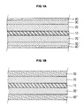
- the electrode includes an electrode collector 10, an electrode active material layer 20, 20' formed on the electrode collector 10.
- a first separator layer 30, 30' containing an electrolyte salt and a binder is on the layer 20, 20'.
- a second separator layer 40, 40' containing ceramic powder is on the first separator layer 30, 30'.
- the electrode according to another embodiment of the present invention includes the electrode collector 10, and the electrode active material layer 20, 20' formed on the electrode collector 10.
- a combined separator layer 50, 50' containing the electrolyte salt, the binder and the ceramic powder is formed on the electrode active material layer 20, 20'.
- the electrode is manufactured using an electrode active material slurry.
- the electrode active material slurry is obtained by mixing and dispersing an electrode active material and a binder.
- the slurry includes a conductive agent in a solvent.
- the slurry is coated on the electrode collector 10 to form the electrode active material layer 20, 20'.
- a polymer solution obtained by mixing and dispersing an electrolyte salt and a binder is coated on the electrode active material layer 20, 20' to form the first separator layer 30, 30'. Then, the ceramic powder is dispersed on the first separator layer 30, 30' to form the second separator layer 40, 40'. By doing so, it is possible to obtain an electrode with good heat resistance.
- the first separator layer 30, 30' is formed before the second separator layer 40, 40', it is possible to eliminate a subsequent drying step or to reduce the time needed for the drying step due to the drying effect provided by the ceramic powder dispersed on the first separator layer 30, 30'. Also, in this case, the first separator layer 30, 30' has an increased level of porosity and provides improved high-rate discharge characteristics.
- the combined separator layer 50, 50' containing the ceramic powder as shown in FIG. 1B, instead of dispersing the ceramic powder on the surface of the first separator layer 30, 30' as shown in FIG. 1A.
- the combined separator layer 50, 50' is formed by mixing and dispersing the electrolyte salt, the binder and the ceramic powder in a solvent to provide a polymer solution and coating the polymer solution on the electrode active material layer 20, 20'. While shown as separate, it is understood that the second layer 40, 40' or the first layer 30, 30' can be used in addition to the layer 50. 50'.
- the coating process for forming the first separator layer 30, 30' and the combined separator layer 50, 50' can be performed by way of any method that does not adversely affect the physical properties of the electrode active material 20, 20'.
- the coating process can be by way of dip coating, spray coating, gravure roll coating, slot die coating, or the like. Any methods of the above methods or combinations thereof may be used in the scope of the present invention.
- the electrolyte salt contained in each of the first separator layer 30, 30' and the combined separator layer 50, 50' includes a salt that can be dissolved in a non-aqueous electrolyte used in a lithium rechargeable battery.
- the electrolyte salt contained in the first separator layer 30, 30' and the combined separator layer 50, 50' is dissolved at least partially in a non-aqueous solvent, so that pores can be formed in the first separator layer 30, 30' and the combined separator layer 50, 50'.
- the lithium secondary battery Due to the pores formed in the first separator layer 30, 30' and the combined separator layer 50, 50', the lithium secondary battery shows improved electrolyte permeability and lithium ion diffusion rate, and thus can provide improved high-rate discharge characteristics.
- the electrolyte is not limited to non-aqueous electrolytes.
- the electrolyte salt contained in the first separator layer 30, 30' and the combined separator layer 50, 50' is a lithium salt.
- the lithium salt that may be used include, but are not limited to, LiPF 6 , LiBF 4 , LiSbF 6 , LiAsF 6 , LiClO 4 , LiCF 3 SO 3 , LiN(CF 3 SO 2 ) 2 N, LiC 4 F 9 SO 3 , LiAlO 4 , LiAlCl 4 , LiN(C x F 2x+1 SO 2 ) (C y F 2x+1 SO 2 ) (wherein each of x and y represents a natural number), LiCl, LiI, or combinations thereof. If such a lithium salt is used as the electrolyte salt, it is possible to increase the capacity of a lithium rechargeable battery because the source of lithium ions, participating in the electrochemical reactions in the battery, increases.
- the binder contained in the first separator layer 30, 30' and the combined separator layer 50, 50' is a polymer resin.
- a polymer resin having a decomposition temperature of 200 °C or higher is preferred.
- binder examples include, but are not limited to, polyvinylidene fluoride (PVDF), polyhexafluoropropylene-polyvinylidene fluoride copolymer (PVdF/HFP), ethylene-tetrafluoroethylene copolymer (ETFE), polychlorotrifluoroethylene (PCTFE), poly(vinyl acetate), polyvinyl alcohol, polyethylene oxide, polyvinyl pyrrolidone, alkylated polyethylene oxide, polyvinyl ether, poly(methyl methacrylate), poly(ethyl acrylate), polytetrafluoroethylene (PTE), polyacrylonitrile, or mixtures thereof.
- PVDF polyvinylidene fluoride
- PVdF/HFP polyhexafluoropropylene-polyvinylidene fluoride copolymer
- EFE ethylene-tetrafluoroethylene copolymer
- PCTFE polychlorotrifluoro
- the electrolyte salt and the binder are used in a weight ratio ranging from 1:1 to 2:1, considering the adhesion to the electrode active material layer 20, 20' and ion conductivity.
- the electrolyte salt, the binder and the ceramic powder are mixed and dispersed in a solvent to provide a polymer solution, and then the polymer solution is coated onto the electrode active material layer 20, 20' to form the combined separator layer 50, 50' containing the ceramic powder, the binder and the ceramic powder may be used in a weight ratio ranging from 5:95 to 20:80.
- other weight ratios can be used.
- the solvent is used to provide the polymer solution by dispersing the electrolyte salt therein, followed by mixing, the binder and/or the ceramic powder. While not required in all aspects, the solvent is selected depending on the kind of the binder. For example, when PVDF is used as the binder, dimethyl formamide or N-methyl pyrrolidone may be used as the solvent. When polyvinyl pyrrolidone is used as the binder, isopropyl alcohol or N-methyl pyrrolidone may be used as the solvent. Additionally, when polyethylene oxide is used as the binder, acetonitrile may be used as the solvent.
- the ceramic powder used in the present invention includes, but is not limited to, the secondary particles of the ceramic material, obtained by partial sintering or recrystallization of the primary particles of the ceramic material.
- the secondary particles are present (preferably) in the shape of hexahedral particle clusters (similar to the shape of a bunch of grapes) or layered particle clusters.
- the primary particles may also be present in the shape of the hexahedral particle clusters or the layered particle clusters, wherein scale-like particles are stacked and bonded to each other.
- an individual particle forming the hexahedral particle clusters or the secondary particles, has an average size/diameter of 0.01 ⁇ 0.3 ⁇ m.
- An individual scale-like flake forming the layered particle clusters has an average width of 100 nm ⁇ 1 ⁇ m.
- the aforementioned dimensions of particles can be determined by observing a photograph of a material having good quality, taken by SEM (scanning electron microscopy).
- the ceramic material that may be used in an aspect of the present invention includes, but is not limited to, silica (SiO 2 ), alumina (Al 2 O 3 ), zirconium oxide (ZrO 2 ), titanium oxide (TiO 2 ), ion conductive glass, or a mixture thereof. Of these, zirconium oxide is preferred.
- Ceramic materials include insulative nitrides, hydroxides or ketones of zirconium, aluminum, silicon or titanium, or combinations thereof.
- insulative nitride is used to exclude a conductive nitride, such as titanium nitride (TiN) from the scope of the ceramic materials suitable to be used in this aspect of the present invention.
- Zirconium oxide shows excellent dispersibility in terms of the zeta( ⁇ ) potential relationship, when mixing and stirring the zirconium oxide with a binder. This provides excellent productivity. Also, zirconium oxide is chemically stable and cost efficient. Moreover, zirconium oxide shows an excellent heat emission property and forms a good p/n bonding along with a lithium compound at high temperature, so that it has diode characteristics. Further, zirconium oxide prevents an excessive amount of lithium ions from being intercalated into an anode.
- the corresponding material is completely dissolved or the surface of the primary particles is partially dissolved by using a chemical substance, followed by recrystallization.
- Particular examples of the physical methods include application of an external pressure.
- an advisable method includes heating the particles to a temperature near the melting point of the particles, followed by necking.
- the ceramic material is molten to such a degree that the resultant combined separator layer 50, 50' can have a low density and the unique particle shape can be maintained, while the paste or dispersion for forming the porous membrane is formed by mixing and agitating the ceramic material with the binder and the solvent.
- the ceramic material e.g. zirconium oxide
- the ceramic material is heated at 900 °C for 10 minutes, a structure of partially sintered particles can be obtained. It is also possible to reprecipitate the ceramic material by dissolving the ceramic material completely by using a solvent providing high solubility to the ceramic material, or by mixing the primary particles with a part of the solvent and removing the solvent.
- the ceramic material preferably has a heat expansion ratio of 0.2% or less at 200 °C and a heat expansion ratio of 0.1 ⁇ 0.4% at 400 °C.
- the heat expansion ratio is a ratio of the volume at a temperature to a volume at room temperature. If the ceramic material has a heat expansion ratio greater than the above range, it may cause an increase in the internal pressure of a battery, resulting in deformation of the battery.
- the ceramic material has a heat conductivity of 10W/(mXK) at a broad range of temperatures ranging from 500 °C to 1000 °C. Additionally, the ceramic material preferably has a relative permittivity of 1 ⁇ 20. If the ceramic material has a relative permittivity greater than 20, it is not possible to provide sufficient capacity. If the ceramic material has a relative permittivity less than 1, it is not possible to form a material having a band gap. Meanwhile, the ceramic material shows an dielectric loss of 10 -5 ⁇ 10 -2 at a frequency of 1MHz. If the dielectric loss is less than 10 -5 , it is not possible to obtain a desired band gap due to the low reproducibility and the porous membrane cannot be produced stably. If the dielectric loss is higher than 10 -2 , it is not possible to obtain sufficient capacity.
- Each of the first separator layer 30, 30' and the combined separator layer 50, 50' has a thickness controlled depending on the ion conductivity and while not required in all aspects, is preferably 5 ⁇ 30 ⁇ m. If each of the first separator layer 30, 30' and the combined separator layer 50, 50' has a thickness less than 1 ⁇ m, the layer shows a low strength. If each of the first separator layer 30, 30' and the combined separator layer 50, 50' has a thickness greater than 40 ⁇ m, overvoltage may occur due to the increased internal resistance. Also, in the latter case, it is not possible to obtain a desired level of energy density.
- each of the first separator layer 30, 30' and the combined separator layer 50, 50' has a porosity of 20 ⁇ 80%, considering the ion conductivity and mechanical strength.
- the ceramic powder may be dispersed and adhered on the surface of the first separator layer 30, 30' in view of the ion conductivity.
- the ceramic powder may be dispersed and adhered on the first separator layer so that it shows a surface coating ratio of 50% or less.
- surface coating ratio means the ratio of the area of the surface of the first separator layer 30, 30' occupied by the ceramic powder to the total area of the surface of the first separator layer 30, 30'.
- the first separator layer 30, 30'/the second separator layer 40, 40', and/or the combined separator layer 50, 50' containing the ceramic powder may be applied to either or both of the cathode and the anode.
- conventional separators may shrink at a high temperature
- the first separator layer 30, 30'/the second separator layer 40, 40', and/or the combined separator layer 50, 50' containing the ceramic powder shows excellent thermal stability so that it cannot be shrunk or molten even when the temperature of a battery increases.
- interstitial volumes may be formed in those layers 30, 40, 50, thereby increasing the porosity. Such pores can contribute to the improvement of electrolyte permeability and lithium ion conductivity in the first separator layer 30, 30' stet the combined separator layer 50, 50'.
- first separator layer 30, 30'/the second separator layer 40, 40' or the combined separator layer containing the ceramic powder functions as a separator by itself, it is possible to avoid a need for an additional separator between both electrodes.
- an additional polyolefin-based separator film is present between both electrodes in a wound electrode assembly, like a conventional lithium rechargeable battery.
- the first separator layer 30, 30'/the second separator layer 40, 40' or the combined separator layer 50, 50' containing the ceramic powder, as well as the polyolefin-based separator film serve as separators for the resultant rechargeable battery.
- the polyolefin-based film separator that may be used in an aspect of the present invention includes a single-layer film of polyethylene or polypropylene, or a multilayer film of polypropylene-polyethylene-polypropylene.
- the cathode of the lithium rechargeable battery includes a cathode active material capable of lithium ion intercalation/deintercalation.
- cathode active materials that may be used in aspects of the present invention include, but are not limited to, at least one composite oxide containing lithium and at least one element selected from the group consisting of cobalt, manganese and nickel.
- Typical examples of the cathode active material that may be used in aspects of the present invention include the following composite oxides (1) to (13): Li x Mn 1-y M y A 2 (1) Li x Mn 1-y M y O 2-z X z (2) Li x Mn 2 M 4-z X z (3) Li x Mn 2-y M y M' z A 4 (4) Li x Co 1-y M y A 2 (5) Li x Co 1-y M y O 2-z AX z (6) Li x Ni 1-y M y A 2 (7) Li x Ni 1-y M y O 2-z X z (8) Li x Ni 1-y Co y O 2-z X z (9) Li x Ni 1-y-z Co y M z A ⁇ (10) Li x Ni 1-y-z Co y M z O 2- ⁇ X ⁇ (11) Li x Ni 1-y-z Mn y M z A ⁇ (12) Li x Ni 1-y-z Mn y M z O 2-
- the anode of the lithium rechargeable battery includes an anode active material capable of lithium ion intercalation/deintercalation.
- anode active materials may include, but are not limited to, carbonaceous materials such as crystalline carbon, amorphous carbon, carbon composites and carbon fiber, lithium metal and lithium alloys.
- the amorphous carbon includes hard carbon, cokes, mesocarbon microbead (MCMB) fired at a temperature of 1500 °C or lower, mesophase pitch-based carbon fiber (MPCF), etc.
- the crystalline carbon includes graphite materials and particular examples thereof include natural graphite, graphitized cokes, graphitized MCMB, graphitized MPCF, etc.
- the carbonaceous material has a d(002) value (interplanar distance) of between 3.351 ⁇ and 3.38 ⁇ , and an Lc value (crystallite size) of at least 20nm, as measured by X-ray diffraction.
- d(002) value interplanar distance
- Lc value crystallite size
- the lithium alloys include alloys of lithium with aluminum, zinc, bismuth, cadmium, antimony, silicon, lead, tin, gallium or indium.
- other materials and/or interplanar distances can be used.
- the collectors 10 usable in the cathode and the anode generally includes, but are not limited to, stainless steel, nickel, aluminum, copper or titanium; alloys thereof; or aluminum, copper or stainless steel, surface-treated with carbon, nickel, titanium or silver.
- the cathode collector that may be used in aspects of the present invention includes, but is not limited to, aluminum or aluminum alloy.
- the anode collector that may be used in the present invention includes but is not limited to copper or copper alloy.
- the cathode collector and the anode collector may take the form of foil, a film, a sheet, a punched body, a porous body or a foamed body. In general, the collector has a thickness of 1 ⁇ 50 ⁇ m, and preferably 1 ⁇ 30 ⁇ m. If the collector is too thin, it shows a low mechanical strength. On the other hand, if the collector is too thick, it occupies the volume of a battery in a high proportion, resulting in a drop in the energy density of the battery.
- the cathode and/or the anode may further comprise a conductive agent.
- the conductive agent that may be used in aspects of the present invention includes, but are not limited to, a graphite-based conductive agent such as artificial graphite or natural graphite; a carbon black-based conductive agent such as acetylene black, ketjen black, denka black, thermal black or channel black; conductive fibers such as carbon fibers or metallic fibers; metal powder such as copper, nickel, aluminum or silver; conductive metal oxides such as titanium oxide; and conductive polymers such as polyaniline, polythiophen, polyacetylene or polypyrrole.
- the aforementioned conductive agents may be used alone or in combination.
- the conductive agent is used, preferably, in an amount of 0.1 ⁇ 10wt% based on the weight of the cathode active material. If the conductive agent is used in an amount less than 0.1wt%, electrochemical characteristics may be degraded. On the other hand, if the conductive agent is used in an amount greater than 10wt%, energy density per unit weight decreases. However, it is understood that other amounts can be used.
- the solvent for use in dispersing the electrode active material, the binder and the conductive agent includes, but is not limited to, a non-aqueous solvent or an aqueous solvent.
- a non-aqueous solvent include N-methyl-2-pyrrolidone (NMP), dimethyl formamide, dimethyl acetamide, N,N-dimethylaminopropylamine, ethylene oxide, tetrahydrofuran, or the like.
- the non-aqueous electrolyte for a lithium rechargeable battery includes a lithium salt and a non-aqueous organic solvent.
- the non-aqueous electrolyte may further include other additives for improving charge/discharge characteristics and for preventing overcharge.
- the lithium salt serves as a source for supplying lithium ions in a battery and empowers a lithium rechargeable battery to perform basic functions.
- the non-aqueous organic solvent functions as a medium, through which ions participating in electrochemical reactions in a battery can move.
- other aspects of the invention include other types of organic and/or polymer electrolytes and/or liquid, solid or gel electrolytes.
- the lithium salt that may be used in aspects of the present invention includes any one salt selected from LiPF 6 , LiBF 4 , LiSbF 6 , LiAsF 6 , LiClO 4 , LiCF 3 SO 3 , Li(CF 3 SO 2 ) 2 N, LiC 4 F 9 SO 3 , LiAlO 4 , LiAlCl 4 , LiN(C x F 2x+1 SO 2 )(CyF 2y+1 SO 2 ) (wherein each of x and y represents a natural number), LiCl, and LiI, or a mixture containing two or more of them.
- the lithium salt is used, preferably, in a concentration of 0.6 ⁇ 2.0M, and more preferably in a concentration of 0.7 ⁇ 1.6M.
- the resultant electrolyte has a low conductivity, resulting in degradation in the quality of the electrolyte. If the lithium salt concentration is greater than 2.0M, the resultant electrolyte has an increased viscosity, resulting in a drop in the lithium ion conductivity.
- the non-aqueous organic solvent may include carbonate, ester, ether or ketone alone, or in combination.
- the organic solvent should have a high dielectric constant (polarity) and low viscosity so as to increase the ion dissociation degree and to facilitate ion conduction.
- a mixed solvent containing at least two solvents including a solvent with a high dielectric constant and high viscosity and a solvent with a low dielectric constant and low viscosity, is preferred.
- the carbonate solvent of an aspect of the invention includes a mixed solvent of a cyclic carbonate with a linear carbonate.
- a cyclic carbonate include, but are not limited to, ethylene carbonate(EC), propylene carbonate (PC), 1,2-butylene carbonate, 2,3-butylene carbonate, 1,2-pentylene carbonate, 2,3-pentylene carbonate, etc.
- Ethylene carbonate and propylene carbonate having a high dielectric constant are preferred.
- ethylene carbonate is preferred.
- linear carbonate examples include, but are not limited to, dimethyl carbonate (DMC), diethyl carbonate (DEC), dipropyl carbonate (DPC), methyl propyl carbonate (MPC), ethyl methyl carbonate (EMC), ethyl propyl carbonate (EPC), etc.
- DMC dimethyl carbonate
- DEC diethyl carbonate
- DPC dipropyl carbonate
- MPC methyl propyl carbonate
- EMC ethyl methyl carbonate
- EPC ethyl propyl carbonate
- ether include tetrahydrofuran, 2-methyltetrahydrofuran, dibutyl ether, etc.
- ketone that may be used in aspects of the present invention include, but are not limited to, polymethyl vinyl ketone, etc.
- LiCoO 2 as a cathode active material, polyvinylidene fluoride as a binder and carbon (Super-P) as a conductive agent were dispersed in N-methyl-2-pyrrolidone as a solvent in the weight ratio of 92:4:4 to form cathode active material slurry.
- the slurry was coated on aluminum foil having a thickness of 15 ⁇ m, dried and rolled to provide a cathode.
- Crystalline artificial graphite as an anode active material and PVDF as a binder were mixed in the weight ratio of 92:8, and the mixture was dispersed in N-methyl-2-pyrrolodone to form anode active material slurry.
- the slurry was coated on copper foil (collector) having a thickness of 10 ⁇ m, dried and rolled to provide an anode.
- the cathode and the anode obtained as described above were wound and compressed together with a separator formed of polyethylene.
- the resultant unit cell was inserted into a prismatic can.
- an electrolyte was added to the can to provide a lithium rechargeable battery.
- LiPF 6 as an electrolyte salt and PVDF as a binder were mixed in the weight ratio of 3:2, and the mixture was dispersed in NMP to form a polymer solution.
- a first separator layer 30, 30' was formed on the anode active material layer obtained as described in Comparative Example 1 by using the polymer solution to a thickness of 10 ⁇ m. Then, zirconium oxide (ZrO 2 ) powder was dispersed on the first separator layer 30, 30' to form a second separator layer 40, 40'.
- ZrO 2 zirconium oxide
- Each of the lithium rechargeable batteries according to Comparative Example 1 and Example 1 was subjected to 3C/3V cut-off discharge, after it is subjected to 20mAh cut-off charge under constant current-constant voltage conditions of 1C/4.2V.
- the 3C discharge capacity of the battery according to Example 1 was calculated by taking the discharge capacity of the battery according to Comparative Example 1 as 100%. The results are shown in the following Table 1.
- the discharge capacity value as shown in Table 1 is the average value of 10 battery samples.
- the number preceding L means the number of batteries used in the test.
- Overcharge safety is evaluated by the following criteria: L0 is excellent; L1 is leakage; L2 is scintillation; L2 is flame; L3 is smoking; L4 is ignition; and L5 is explosion.
- 10L0 means that all of the ten batteries used in the test show excellent safety.
- Table 1 1C-12V Overcharge Penetration 3C Discharge Capacity (%) Comp. Ex. 1 10L4 10L4 100% Ex. 1 10L0 10L0 150%
- the lithium rechargeable battery according to aspects of the present invention has excellent thermal safety and shows excellent high-rate discharge characteristics.
Landscapes
- Chemical & Material Sciences (AREA)
- Chemical Kinetics & Catalysis (AREA)
- Electrochemistry (AREA)
- General Chemical & Material Sciences (AREA)
- Engineering & Computer Science (AREA)
- Manufacturing & Machinery (AREA)
- Materials Engineering (AREA)
- Composite Materials (AREA)
- Inorganic Chemistry (AREA)
- Secondary Cells (AREA)
- Cell Separators (AREA)
- Battery Electrode And Active Subsutance (AREA)
Applications Claiming Priority (1)
| Application Number | Priority Date | Filing Date | Title |
|---|---|---|---|
| KR1020050095469A KR100686848B1 (ko) | 2005-10-11 | 2005-10-11 | 리튬 이차 전지 |
Publications (3)
| Publication Number | Publication Date |
|---|---|
| EP1777761A2 true EP1777761A2 (de) | 2007-04-25 |
| EP1777761A3 EP1777761A3 (de) | 2007-05-02 |
| EP1777761B1 EP1777761B1 (de) | 2010-06-02 |
Family
ID=37808235
Family Applications (1)
| Application Number | Title | Priority Date | Filing Date |
|---|---|---|---|
| EP06121984A Active EP1777761B1 (de) | 2005-10-11 | 2006-10-09 | Wiederaufladbare Lithiumbatterie |
Country Status (4)
| Country | Link |
|---|---|
| US (1) | US20070082261A1 (de) |
| EP (1) | EP1777761B1 (de) |
| KR (1) | KR100686848B1 (de) |
| DE (1) | DE602006014635D1 (de) |
Cited By (4)
| Publication number | Priority date | Publication date | Assignee | Title |
|---|---|---|---|---|
| CZ301387B6 (cs) * | 2008-09-19 | 2010-02-10 | He3Da S.R.O. | Lithiový akumulátor s prostorovým typem elektrod a zpusob jeho výroby |
| ES2352492A1 (es) * | 2009-05-22 | 2011-02-21 | Universidad De Málaga | Batería transparente secundaria de ión litio. |
| EP1998401A3 (de) * | 2007-05-25 | 2011-06-22 | Samsung SDI Co., Ltd. | Elektrodenanordnung und Sekundärbatterie damit |
| WO2013005135A1 (en) | 2011-07-01 | 2013-01-10 | He3Da S.R.O. | Lithium accumulator |
Families Citing this family (33)
| Publication number | Priority date | Publication date | Assignee | Title |
|---|---|---|---|---|
| JP5400268B2 (ja) * | 2006-01-26 | 2014-01-29 | パナソニック株式会社 | リチウム二次電池 |
| CN101479877B (zh) * | 2006-05-04 | 2013-07-31 | 株式会社Lg化学 | 锂二次电池及其制造方法 |
| CN101494302B (zh) * | 2008-01-22 | 2012-10-03 | 索尼株式会社 | 电池 |
| US20100221965A1 (en) * | 2008-01-29 | 2010-09-02 | Hitachi Maxell, Ltd. | Slurry for forming insulating layer, separator for electrochemical device, method for producing the same, and electrochemical device |
| US9312076B1 (en) * | 2009-12-30 | 2016-04-12 | University Of West Florida | Very high energy-density ultracapacitor apparatus and method |
| KR101173867B1 (ko) * | 2010-10-28 | 2012-08-14 | 삼성에스디아이 주식회사 | 리튬 이차 전지 |
| US20120231321A1 (en) | 2011-03-11 | 2012-09-13 | GM Global Technology Operations LLC | Integral bi-layer separator-electrode construction for lithium-ion batteries |
| KR102144598B1 (ko) * | 2011-11-18 | 2020-08-13 | 스미또모 가가꾸 가부시끼가이샤 | 적층 다공질 필름 및 그 제조 방법, 그리고 비수 전해액 2 차 전지용 세퍼레이터, 적층 전극 시트 및 비수 전해액 2 차 전지 |
| KR101515357B1 (ko) * | 2012-02-29 | 2015-04-28 | 제일모직주식회사 | 유기 및 무기 혼합물 코팅층을 포함하는 분리막 및 이를 이용한 전지 |
| KR101488919B1 (ko) * | 2012-02-29 | 2015-02-03 | 제일모직 주식회사 | 유기 및 무기 혼합물 코팅층을 포함하는 분리막 및 이를 이용한 전지 |
| KR101488917B1 (ko) * | 2012-02-29 | 2015-02-03 | 제일모직 주식회사 | 유기 및 무기 혼합물 코팅층을 포함하는 분리막 및 이를 이용한 전지 |
| KR102391775B1 (ko) * | 2012-08-07 | 2022-04-28 | 셀가드 엘엘씨 | 리튬 이온 배터리용의 개선된 세퍼레이터 막 및 관련 방법 |
| KR20140065644A (ko) * | 2012-11-19 | 2014-05-30 | 주식회사 엘지화학 | 양극 활물질 조성물 및 이를 포함하는 리튬 이차 전지 |
| CN103311500B (zh) * | 2013-05-15 | 2016-02-24 | 深圳市慧通天下科技股份有限公司 | 一种锂离子电池负极极片及制作方法 |
| CN104377328B (zh) * | 2013-08-14 | 2019-09-13 | 三星Sdi株式会社 | 可再充电锂电池 |
| JP5843116B2 (ja) * | 2013-10-04 | 2016-01-13 | トヨタ自動車株式会社 | 非水電解質二次電池 |
| DE102013226064A1 (de) * | 2013-12-16 | 2015-06-18 | Robert Bosch Gmbh | Verfahren zur Herstellung einer Funktionsschicht für eine Lithium-Zelle |
| JP6327011B2 (ja) * | 2014-06-26 | 2018-05-23 | 株式会社豊田自動織機 | 蓄電装置用電極、蓄電装置及び蓄電装置用電極の製造方法 |
| KR102349957B1 (ko) * | 2014-09-05 | 2022-01-11 | 삼성전자주식회사 | 유무기 실리콘 구조체 함유 블록 공중합체, 이를 포함하는 전해질, 및 상기 전해질을 포함하는 리튬전지 |
| JP6654924B2 (ja) * | 2016-02-18 | 2020-02-26 | 積水化学工業株式会社 | リチウムイオン二次電池の製造方法 |
| WO2018071322A1 (en) * | 2016-10-10 | 2018-04-19 | Temple University-Of The Commonwealth System Of Higher Education | Silanated silica-ceramic materials, organic-modified metal-oxide-coated ceramic materials and methods of making and using |
| JP7279298B2 (ja) | 2017-03-06 | 2023-05-23 | 株式会社リコー | 電極 |
| EP4567936A3 (de) | 2017-03-06 | 2025-09-03 | Ricoh Company, Ltd. | Filmelektrode, harzschichtbildende tinte, anorganische schichtbildende tinte und elektrodendruckvorrichtung |
| US11646410B2 (en) | 2017-12-07 | 2023-05-09 | Lg Energy Solution, Ltd. | Anode for lithium metal battery, and electrochemical device comprising same |
| EP3776692A4 (de) | 2018-04-06 | 2021-12-29 | Celgard, LLC | Festkörperbatterien, sse-batterien, lithiummetallbatterien mit festelektrolyten, hsse, separatoren und/oder beschichtungen und/oder verwandte verfahren |
| US10637100B2 (en) * | 2018-04-20 | 2020-04-28 | Ut-Battelle, Llc | Fabrication of films and coatings used to activate shear thickening, impact resistant electrolytes |
| JP7044174B2 (ja) * | 2018-11-30 | 2022-03-30 | 株式会社村田製作所 | 二次電池 |
| CN112151728B (zh) * | 2019-06-28 | 2022-04-15 | 比亚迪股份有限公司 | 一种锂离子电池复合隔膜及其制备方法、锂离子电池 |
| US11417888B2 (en) * | 2019-09-17 | 2022-08-16 | GM Global Technology Operations LLC | Electrode additives and coatings for minimizing cathode transition metal dissolution |
| EP4197052A4 (de) * | 2020-08-12 | 2024-09-18 | Dragonfly Energy Corp. | Pulverförmiger feststoffelektrolyt und elektroaktive materialien |
| WO2022038670A1 (ja) * | 2020-08-18 | 2022-02-24 | TeraWatt Technology株式会社 | リチウム2次電池 |
| WO2024226572A2 (en) * | 2023-04-25 | 2024-10-31 | Energy Exploration Technologies, Inc. | A secondary hybrid solid-state battery and methods of making thereof |
| US12567600B2 (en) | 2023-12-14 | 2026-03-03 | Safire Technology Group, Inc. | Systems and methods for enhancing safety of electrochemical cells via electrolyte thickening |
Family Cites Families (33)
| Publication number | Priority date | Publication date | Assignee | Title |
|---|---|---|---|---|
| WO1989009473A1 (en) * | 1988-03-30 | 1989-10-05 | Elmwood Sensors Limited | Conductive ceramics, conductors thereof and methods |
| DE69404602T2 (de) * | 1993-10-07 | 1998-01-29 | Matsushita Electric Ind Co Ltd | Herstellungsverfahren eines Separators für eine Lithium-Sekundärbatterie und eine Lithium-Sekundärbatterie mit organischem Elektrolyt, die einen solchen Separator verwendet |
| JPH0864203A (ja) * | 1994-08-25 | 1996-03-08 | Ricoh Co Ltd | 電極、電極の製造方法および該電極を用いた二次電池 |
| US6365299B1 (en) * | 1995-06-28 | 2002-04-02 | Fuji Photo Film Co., Ltd. | Nonaqueous secondary battery |
| CA2226366C (en) * | 1995-08-28 | 2002-05-21 | Asahi Kasei Kogyo Kabushiki Kaisha | Novel battery and method for producing the same |
| US5925483A (en) * | 1996-05-06 | 1999-07-20 | Kejha; Joseph B. | Multi-layer polymeric electrolytes for electrochemical devices |
| KR19980051248U (ko) * | 1996-12-30 | 1998-10-07 | 손욱 | 전지용 격리판 |
| US6753114B2 (en) * | 1998-04-20 | 2004-06-22 | Electrovaya Inc. | Composite electrolyte for a rechargeable lithium battery |
| DE19850826A1 (de) * | 1998-11-04 | 2000-05-11 | Basf Ag | Als Separatoren in elektrochemischen Zellen geeignete Verbundkörper |
| US6277514B1 (en) * | 1998-12-17 | 2001-08-21 | Moltech Corporation | Protective coating for separators for electrochemical cells |
| WO2000079618A1 (fr) * | 1999-06-22 | 2000-12-28 | Mitsubishi Denki Kabushiki Kaisha | Separateur de cellule, cellule, et procede de production dudit separateur |
| US6692873B1 (en) * | 1999-08-05 | 2004-02-17 | Skc Co., Ltd. | Composition for forming electrode active material of lithium secondary battery, composition for forming separator and method of preparing lithium secondary battery using the compositions |
| US6562511B2 (en) * | 1999-12-09 | 2003-05-13 | Ntk Powerdex, Inc. | Battery separator for Li-Ion and/or Li-Ion polymer battery |
| US20020136945A1 (en) * | 2000-01-18 | 2002-09-26 | Call Ronald W. | Multilayer battery separators |
| US6432586B1 (en) * | 2000-04-10 | 2002-08-13 | Celgard Inc. | Separator for a high energy rechargeable lithium battery |
| US6699618B2 (en) * | 2000-04-26 | 2004-03-02 | Showa Denko K.K. | Cathode electroactive material, production method therefor and secondary cell |
| JP3692965B2 (ja) * | 2000-05-15 | 2005-09-07 | 株式会社デンソー | リチウム二次電池およびその正極の製造方法 |
| TWI315591B (en) * | 2000-06-14 | 2009-10-01 | Sumitomo Chemical Co | Porous film and separator for battery using the same |
| DE60144235D1 (de) * | 2000-08-12 | 2011-04-28 | Lg Chemical Ltd | Zusammengesetzter film mit mehreren komponenten und verfahren zu seiner herstellung |
| US6727017B1 (en) * | 2001-04-06 | 2004-04-27 | Changs Ascending Enterprise Co., Ltd. | Methods of fabricating binding layers for a Li-ion polymer battery |
| JP3960193B2 (ja) * | 2001-12-20 | 2007-08-15 | 株式会社デンソー | リチウム二次電池用電極及びリチウム二次電池並びにその製造方法 |
| KR100454030B1 (ko) * | 2002-08-07 | 2004-10-20 | 삼성에스디아이 주식회사 | 리튬-황 전지용 양극, 이의 제조 방법 및 이를 포함하는리튬-황 전지 |
| KR100573358B1 (ko) * | 2002-09-17 | 2006-04-24 | 가부시키가이샤 도모에가와 세이시쇼 | 리튬이온2차전지용 세퍼레이터 및 이를 포함한리튬이온2차전지 |
| JP4777593B2 (ja) * | 2002-11-29 | 2011-09-21 | 株式会社オハラ | リチウムイオン二次電池の製造方法 |
| JP2004220819A (ja) * | 2003-01-09 | 2004-08-05 | Sony Corp | 電解質、負極および電池 |
| JP4045989B2 (ja) * | 2003-03-25 | 2008-02-13 | 松下電器産業株式会社 | 電気化学素子用セパレータ |
| KR100542213B1 (ko) * | 2003-10-31 | 2006-01-10 | 삼성에스디아이 주식회사 | 리튬 금속 전지용 음극 및 이를 포함하는 리튬 금속 전지 |
| US20050100794A1 (en) * | 2003-11-06 | 2005-05-12 | Tiax, Llc | Separator for electrochemical devices and methods |
| US20050214236A1 (en) * | 2003-12-23 | 2005-09-29 | Qinyun Peng | Surface treated pearlescent pigments for hair care products |
| JP2005285385A (ja) * | 2004-03-29 | 2005-10-13 | Sanyo Electric Co Ltd | セパレータ及びこのセパレータを用いた非水電解質電池 |
| US7604895B2 (en) * | 2004-03-29 | 2009-10-20 | Lg Chem, Ltd. | Electrochemical cell with two types of separators |
| WO2006068255A1 (ja) * | 2004-12-24 | 2006-06-29 | Nippon Sheet Glass Company, Limited | 鱗片状ガラス |
| US7776478B2 (en) * | 2005-07-15 | 2010-08-17 | Cymbet Corporation | Thin-film batteries with polymer and LiPON electrolyte layers and method |
-
2005
- 2005-10-11 KR KR1020050095469A patent/KR100686848B1/ko not_active Expired - Lifetime
-
2006
- 2006-10-09 EP EP06121984A patent/EP1777761B1/de active Active
- 2006-10-09 DE DE602006014635T patent/DE602006014635D1/de active Active
- 2006-10-10 US US11/544,602 patent/US20070082261A1/en not_active Abandoned
Cited By (8)
| Publication number | Priority date | Publication date | Assignee | Title |
|---|---|---|---|---|
| EP1998401A3 (de) * | 2007-05-25 | 2011-06-22 | Samsung SDI Co., Ltd. | Elektrodenanordnung und Sekundärbatterie damit |
| US8420248B2 (en) | 2007-05-25 | 2013-04-16 | Samsung Sdi Co., Ltd. | Electrode assembly and secondary battery using the same |
| US8808902B2 (en) | 2007-05-25 | 2014-08-19 | Samsung Sdi Co., Ltd. | Electrode assembly including ceramic layer disposed along the length of the positive electrode and secondary battery using the same |
| CZ301387B6 (cs) * | 2008-09-19 | 2010-02-10 | He3Da S.R.O. | Lithiový akumulátor s prostorovým typem elektrod a zpusob jeho výroby |
| ES2352492A1 (es) * | 2009-05-22 | 2011-02-21 | Universidad De Málaga | Batería transparente secundaria de ión litio. |
| WO2010133735A3 (es) * | 2009-05-22 | 2011-07-14 | Universidad De Malaga | Batería transparente secundaria de ion litio |
| WO2013005135A1 (en) | 2011-07-01 | 2013-01-10 | He3Da S.R.O. | Lithium accumulator |
| US9401510B2 (en) | 2011-07-01 | 2016-07-26 | He3Da S.R.O. | Lithium accumulator |
Also Published As
| Publication number | Publication date |
|---|---|
| DE602006014635D1 (de) | 2010-07-15 |
| EP1777761A3 (de) | 2007-05-02 |
| US20070082261A1 (en) | 2007-04-12 |
| EP1777761B1 (de) | 2010-06-02 |
| KR100686848B1 (ko) | 2007-02-26 |
Similar Documents
| Publication | Publication Date | Title |
|---|---|---|
| EP1777761B1 (de) | Wiederaufladbare Lithiumbatterie | |
| KR102417200B1 (ko) | 리튬 이차전지용 음극, 이의 제조방법 및 상기 리튬 이차전지용 음극을 포함하는 리튬 이차전지 | |
| EP3712983A1 (de) | Separator und elektrochemische vorrichtung | |
| KR100659854B1 (ko) | 리튬 이차 전지 | |
| US7659036B2 (en) | Lithium rechargeable battery including a porous membrane separator formed of ceramic secondary particles and a binder | |
| CN101414680B (zh) | 正极活性物质、正极和非水电解质二次电池 | |
| US8835059B2 (en) | Lithium rechargeable battery, and separator for lithium rechargeable battery | |
| KR100670507B1 (ko) | 리튬 이차 전지 | |
| KR102132878B1 (ko) | 리튬 이차전지용 양극 활물질, 이의 제조방법, 이를 포함하는 리튬 이차전지용 양극 및 리튬 이차전지 | |
| US8592070B2 (en) | Lithium rechargeable battery | |
| US20170092922A1 (en) | Non-aqueous electrolyte battery | |
| KR102564970B1 (ko) | 음극 및 이를 포함하는 이차전지 | |
| US10541453B2 (en) | Battery module for starting a power equipment | |
| CN101431151A (zh) | 正极和锂离子二次电池 | |
| KR101723993B1 (ko) | 리튬 이차 전지용 음극 및 이의 제조 방법, 및 이를 포함하는 리튬 이차 전지 | |
| KR102947098B1 (ko) | 이차전지용 양극, 그 제조방법 및 이를 포함하는 리튬 이차전지 | |
| KR102567400B1 (ko) | 이차전지 | |
| KR102206590B1 (ko) | 리튬 이차전지용 양극 활물질, 이의 제조방법, 이를 포함하는 리튬 이차전지용 양극 및 리튬 이차전지 | |
| EP4106049B1 (de) | Positivelektrode für lithiumsekundärbatterie und lithiumsekundärbatterie | |
| KR20220103469A (ko) | 이차전지의 충방전 방법 | |
| KR100485204B1 (ko) | 리튬2차전지용캐소드 | |
| JP2002279956A (ja) | 非水電解質電池 | |
| CN101645503B (zh) | 正极活性物质、使用其的正极以及非水电解质二次电池 | |
| KR102248105B1 (ko) | 양극 활물질 및 이를 포함하는 리튬 이차전지 | |
| KR20180093593A (ko) | 이차전지용 양극활물질 및 이의 제조방법 |
Legal Events
| Date | Code | Title | Description |
|---|---|---|---|
| PUAI | Public reference made under article 153(3) epc to a published international application that has entered the european phase |
Free format text: ORIGINAL CODE: 0009012 |
|
| PUAL | Search report despatched |
Free format text: ORIGINAL CODE: 0009013 |
|
| 17P | Request for examination filed |
Effective date: 20061009 |
|
| AK | Designated contracting states |
Kind code of ref document: A2 Designated state(s): AT BE BG CH CY CZ DE DK EE ES FI FR GB GR HU IE IS IT LI LT LU LV MC NL PL PT RO SE SI SK TR |
|
| AX | Request for extension of the european patent |
Extension state: AL BA HR MK YU |
|
| AK | Designated contracting states |
Kind code of ref document: A3 Designated state(s): AT BE BG CH CY CZ DE DK EE ES FI FR GB GR HU IE IS IT LI LT LU LV MC NL PL PT RO SE SI SK TR |
|
| AX | Request for extension of the european patent |
Extension state: AL BA HR MK YU |
|
| RIC1 | Information provided on ipc code assigned before grant |
Ipc: H01M 2/16 20060101AFI20070327BHEP Ipc: H01M 10/40 20060101ALN20070327BHEP Ipc: H01M 10/42 20060101ALI20070327BHEP Ipc: H01M 4/02 20060101ALN20070327BHEP |
|
| AKX | Designation fees paid |
Designated state(s): DE FR GB HU |
|
| 17Q | First examination report despatched |
Effective date: 20071227 |
|
| RAP1 | Party data changed (applicant data changed or rights of an application transferred) |
Owner name: SAMSUNG SDI CO., LTD. |
|
| GRAP | Despatch of communication of intention to grant a patent |
Free format text: ORIGINAL CODE: EPIDOSNIGR1 |
|
| GRAS | Grant fee paid |
Free format text: ORIGINAL CODE: EPIDOSNIGR3 |
|
| GRAA | (expected) grant |
Free format text: ORIGINAL CODE: 0009210 |
|
| AK | Designated contracting states |
Kind code of ref document: B1 Designated state(s): DE FR GB HU |
|
| REG | Reference to a national code |
Ref country code: GB Ref legal event code: FG4D |
|
| REF | Corresponds to: |
Ref document number: 602006014635 Country of ref document: DE Date of ref document: 20100715 Kind code of ref document: P |
|
| PLBE | No opposition filed within time limit |
Free format text: ORIGINAL CODE: 0009261 |
|
| STAA | Information on the status of an ep patent application or granted ep patent |
Free format text: STATUS: NO OPPOSITION FILED WITHIN TIME LIMIT |
|
| 26N | No opposition filed |
Effective date: 20110303 |
|
| REG | Reference to a national code |
Ref country code: DE Ref legal event code: R097 Ref document number: 602006014635 Country of ref document: DE Effective date: 20110302 |
|
| PG25 | Lapsed in a contracting state [announced via postgrant information from national office to epo] |
Ref country code: HU Free format text: LAPSE BECAUSE OF FAILURE TO SUBMIT A TRANSLATION OF THE DESCRIPTION OR TO PAY THE FEE WITHIN THE PRESCRIBED TIME-LIMIT Effective date: 20101203 |
|
| REG | Reference to a national code |
Ref country code: FR Ref legal event code: PLFP Year of fee payment: 11 |
|
| REG | Reference to a national code |
Ref country code: FR Ref legal event code: PLFP Year of fee payment: 12 |
|
| REG | Reference to a national code |
Ref country code: FR Ref legal event code: PLFP Year of fee payment: 13 |
|
| REG | Reference to a national code |
Ref country code: DE Ref legal event code: R079 Ref document number: 602006014635 Country of ref document: DE Free format text: PREVIOUS MAIN CLASS: H01M0002140000 Ipc: H01M0050400000 |
|
| P01 | Opt-out of the competence of the unified patent court (upc) registered |
Effective date: 20230528 |
|
| PGFP | Annual fee paid to national office [announced via postgrant information from national office to epo] |
Ref country code: FR Payment date: 20250930 Year of fee payment: 20 |
|
| PGFP | Annual fee paid to national office [announced via postgrant information from national office to epo] |
Ref country code: DE Payment date: 20250930 Year of fee payment: 20 |
|
| PGFP | Annual fee paid to national office [announced via postgrant information from national office to epo] |
Ref country code: GB Payment date: 20251001 Year of fee payment: 20 |