EP1777791A2 - Pièce de finition et/ou de liaison - Google Patents
Pièce de finition et/ou de liaison Download PDFInfo
- Publication number
- EP1777791A2 EP1777791A2 EP06021384A EP06021384A EP1777791A2 EP 1777791 A2 EP1777791 A2 EP 1777791A2 EP 06021384 A EP06021384 A EP 06021384A EP 06021384 A EP06021384 A EP 06021384A EP 1777791 A2 EP1777791 A2 EP 1777791A2
- Authority
- EP
- European Patent Office
- Prior art keywords
- connecting piece
- terminating
- cover
- connection
- profile
- Prior art date
- Legal status (The legal status is an assumption and is not a legal conclusion. Google has not performed a legal analysis and makes no representation as to the accuracy of the status listed.)
- Withdrawn
Links
- 238000003825 pressing Methods 0.000 claims description 4
- 238000000465 moulding Methods 0.000 claims description 3
- 239000000463 material Substances 0.000 description 16
- 239000004033 plastic Substances 0.000 description 10
- 229920003023 plastic Polymers 0.000 description 10
- 239000000758 substrate Substances 0.000 description 4
- 230000008901 benefit Effects 0.000 description 3
- 238000003780 insertion Methods 0.000 description 3
- 230000037431 insertion Effects 0.000 description 3
- 230000007704 transition Effects 0.000 description 3
- 238000004026 adhesive bonding Methods 0.000 description 2
- 239000000872 buffer Substances 0.000 description 2
- 238000005520 cutting process Methods 0.000 description 2
- 238000013461 design Methods 0.000 description 2
- 239000013013 elastic material Substances 0.000 description 2
- 238000001125 extrusion Methods 0.000 description 2
- 238000001746 injection moulding Methods 0.000 description 2
- 230000036961 partial effect Effects 0.000 description 2
- 230000035515 penetration Effects 0.000 description 2
- 230000000284 resting effect Effects 0.000 description 2
- 239000004952 Polyamide Substances 0.000 description 1
- 230000032683 aging Effects 0.000 description 1
- 230000001419 dependent effect Effects 0.000 description 1
- 238000011161 development Methods 0.000 description 1
- 230000018109 developmental process Effects 0.000 description 1
- 230000005489 elastic deformation Effects 0.000 description 1
- 229920001971 elastomer Polymers 0.000 description 1
- 239000000945 filler Substances 0.000 description 1
- 230000005484 gravity Effects 0.000 description 1
- 230000001976 improved effect Effects 0.000 description 1
- 230000001965 increasing effect Effects 0.000 description 1
- 238000009434 installation Methods 0.000 description 1
- SZVJSHCCFOBDDC-UHFFFAOYSA-N iron(II,III) oxide Inorganic materials O=[Fe]O[Fe]O[Fe]=O SZVJSHCCFOBDDC-UHFFFAOYSA-N 0.000 description 1
- 230000000670 limiting effect Effects 0.000 description 1
- 238000004519 manufacturing process Methods 0.000 description 1
- 239000002184 metal Substances 0.000 description 1
- 229910052751 metal Inorganic materials 0.000 description 1
- 238000012986 modification Methods 0.000 description 1
- 239000002991 molded plastic Substances 0.000 description 1
- 229920002647 polyamide Polymers 0.000 description 1
- 230000002829 reductive effect Effects 0.000 description 1
- 230000003014 reinforcing effect Effects 0.000 description 1
- 239000005060 rubber Substances 0.000 description 1
- 230000009183 running Effects 0.000 description 1
- 238000007493 shaping process Methods 0.000 description 1
- 238000003860 storage Methods 0.000 description 1
- 210000002105 tongue Anatomy 0.000 description 1
- 238000012549 training Methods 0.000 description 1
- 230000003313 weakening effect Effects 0.000 description 1
- 238000003466 welding Methods 0.000 description 1
Images





Classifications
-
- H—ELECTRICITY
- H02—GENERATION; CONVERSION OR DISTRIBUTION OF ELECTRIC POWER
- H02G—INSTALLATION OF ELECTRIC CABLES OR LINES, OR OF COMBINED OPTICAL AND ELECTRIC CABLES OR LINES
- H02G3/00—Installations of electric cables or lines or protective tubing therefor in or on buildings, equivalent structures or vehicles
- H02G3/02—Details
- H02G3/06—Joints for connecting lengths of protective tubing or channels, to each other or to casings, e.g. to distribution boxes; Ensuring electrical continuity in the joint
- H02G3/0608—Joints for connecting non cylindrical conduits, e.g. channels
-
- H—ELECTRICITY
- H02—GENERATION; CONVERSION OR DISTRIBUTION OF ELECTRIC POWER
- H02G—INSTALLATION OF ELECTRIC CABLES OR LINES, OR OF COMBINED OPTICAL AND ELECTRIC CABLES OR LINES
- H02G9/00—Installations of electric cables or lines in or on the ground or water
- H02G9/02—Installations of electric cables or lines in or on the ground or water laid directly in or on the ground, river-bed or sea-bottom; Coverings therefor, e.g. tile
- H02G9/025—Coverings therefor, e.g. tile
Definitions
- the invention relates to a terminating and / or connecting piece for use with at least one cover profile or a cable bridge for cables according to the preamble of claim 1.
- a cover profile which is also suitable in particular as a cable bridge is known (US Pat. DE 101 48 937 ) consisting of a profile body produced by extrusion, which has at least one channel for receiving lines and / or cables and at least at edge regions of its longitudinal sides made of a material (plastic) whose density is greater than 1.8 g / cm 3 and its Modulus of elasticity is less than 500 N / mm 2 .
- This design ensures that the cover after laying on a substrate, for example, not only tightly rests on the floor of a building interior, but also conforms to bumps, without further attachment measures, so that, inter alia, an accident by tripping over this cover effective is avoided.
- Object of the present invention is to show a terminating and / or connecting piece, which can be attached in a form-fitting manner to the at least one end of the cover profile, without gluing and without the risk that the positive and thus non-positive connection between the terminator and / or connector and the cover profile is lost due to aging phenomena, such as material fatigue or creep of the material.
- the positive connection between the covering or cable bridge profile and the terminating and / or connecting piece can in principle in the invention be realized without the use of an additional tool, since the positive connection causing connecting means are integrated in the terminating and / or connecting piece.
- the terminating and / or connecting piece itself forms the tool which is required for the production of the positive connection with the cover profile.
- the positive connection achieved with the invention is very effective or highly resilient and is not subject to weakening due to material fatigue or material creep, although the cover itself can be produced as an extruded profile without undercuts that would be suitable for a kaftschlüssige connection.
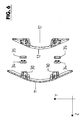
- the figures further indicate the three mutually perpendicular spatial axes, namely the X-axis, Y-axis and Z-axis.
- 1 is a cover profile or cable channel, which consists essentially of a profile body 2 made of plastic produced by extrusion, whose density is greater than 1.8 g / cm 3 and whose modulus of elasticity is less than 500 N / mm 2 , so that the Cover profile 1 and its profile body 2 when laying on a substrate. 3 by the high specific gravity or high density and by the low modulus of elasticity "slack” or at least largely “slack” rests flat on this substrate 3 in particular with the edge areas and unevenness of the substrate 3 follows.
- the profile body 2 is convexly curved on its upper side about axes in the profile longitudinal direction or in the direction of the X-axis and has a plurality of channels 4 and 5 extending in the longitudinal direction of the profile, which are respectively accessible on the flat underside of the profile body 2 and for receiving Serve cables or lines of various kinds.
- a further, closed channel 7 is introduced into the profile body 2, which also extends like the channels 4 and 5 over the entire length of the cover profile 1.
- the (layer) forms the convexly curved top of the cover profile 1.
- a cover profile of this type is the subject of German Patent 101 48 937.
- the cover profile 1 in addition to the layer 8, which forms the top of this cover also a layer 8.1, which forms the underside of the cover 1 and consists of a rubber-elastic plastic. From the layer 8.1 forming material and the openings of the channels 4 and 5 limiting elastic lips 4.1 and 5.1 are formed. Furthermore, the inner surfaces of the channels 4 and 5 are coated with the material of the layer 8.1.
- This training has the advantage that a tearing of the respective cover profile 1 when inserting the lines 6 in the channels 4 and 5 and in the case taking place elastic deformation of the cover is effectively prevented, even if for the profile body 2 to increase its Dense plastic material is used, which has a particularly high proportion of a density-increasing filler, such as magnetite.
- the layer 8.1 is applied to the profile body 2 completely enveloping, so that the layer 8.1 extends below the layer 8.
- FIGs 1 - 11 denotes a closure piece, which is provided at one end of the cover 1, where the lines 6 from the Cover profile 1 are led out to lead these lines 6, for example, at a work table, eg at the bottom of the work table upwards.
- the end piece 10 may also be provided for other reasons at the respective end of a cover profile 1, for example, to connect the lines 6 with a provided in the building floor 3 or on a building wall building side installation etc.
- end caps 10 for example, where provided connect several cover profiles 1 to each other, for example, to distribute the existing first in a cover profile 1 lines 6 in several directions, as indicated in the figure 1 with broken lines.
- the end piece 10 is made in two parts and consists of an upper cap or upper part 11 and a lower part 12. Both parts are molded plastic parts, d. H. made by injection molding of plastic, and indeed of a plastic with sufficient strength, such as polyamide.
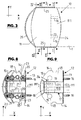
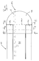
- the lower part has in plan view on the top and bottom the shape shown in Figures 8 and 9, i. a flat front face 13, which forms the connection area or the connection surface for connection to the cover profile 1 and to each of which a shorter, rectilinear edge 14 connects at right angles.
- a flat front face 13 which forms the connection area or the connection surface for connection to the cover profile 1 and to each of which a shorter, rectilinear edge 14 connects at right angles.
- the lower part 12 in the plan view of Figures 8 and 9 is curved in a circular arc convex.
- pins 16 are formed, each having a plurality of annular notches, attached at the end of the cover profile 1 end piece 10 each in one Channel 7 engage and thereby connect the lower part 12 with respect to the longitudinal extent of the cover or X-axis radially positive fit with the cover profile 1.
- the end face 13 of the lower part 12 is further formed so that this same shape adjoins the end of the cover, ie at its bottom resting on the bottom 3
- Base 12 is the convex curved upper edge of the end face 13 flush with the outer surface of the cover 1 formed by the layer 8.
- the lower part 12 thus has at least on the end face 13 has a cross section whose outer contour corresponds to the cross section and the outer contour of the cover 1 ,
- the lower part 12 is furthermore shaped such that it forms on its underside a channel 17 which extends from the front side 13 to the rear side 15 or in the direction of the X-axis and which is open at the underside of the lower part 12 and opens at the end face 13 between the two projections or pin 16.
- the channel 17 is bounded by two lateral wall portions 17.1 and an upper wall portion 17.2, which forms the top of the upper part and the shape of the top of the cover 1 according to the top of the lower part convex and concavely curved on the inside of the channel 17.
- the width of the channel 17 is slightly increased by the there slanted wall sections 17.1 at 17.1.1 to improve the possibility of lateral lead out of lines 6, as shown in Figure 9 for the local line 6 with broken lines is indicated.
- the lower part 12 On both sides of the channel 17, the lower part 12 each have a flat bottom forming wall portion 18, with which the lower part 12 rests on the bottom 3.
- a rubber elastic material slip buffer 19 On the underside of the illustrated embodiment made of a rubber elastic material slip buffer 19 are provided.
- each wall portion 18 on each side of the closed channel 17 each have three hollow pins 20, 21 and 22 and also reinforcing webs formed, which extend partially between the hollow pin and between the hollow pin and the side edge 14 of the lower part.
- the hollow pins 20 - 22 and the webs 23 are formed so that they lie within the contour formed by the upper, convexly curved edge of the end face 13.
- the lower part 12 is slightly bevelled, in particular on the upper boundary wall, so that there the rear part 12 has a somewhat reduced height.
- the lower part 12 is formed in the illustrated embodiment mirror-symmetrical to a center plane M1, which is oriented perpendicular to the underside of the lower part 12 formed by the wall sections 18 and is an X-Y plane.
- the upper part 11 is formed as a cap, in such a way that it can be fitted to the lower part 12 and then fits this lower part fitting.
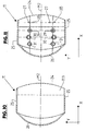
- the upper part 11 thus has the FIGS. 10 and 11 in plan view a shaping with a convexly curved front edge 24, two straight edges 25 adjoining the edge 24 and a convexly curved rear edge 26, is on its underside the course or The contour of the top of the cover 1 according to concavely curved and otherwise formed so that it completely covers after placing on the lower part 12th
- the edges 25 are then adjacent to the edges 14 and the rear side 26 of the rear side 15, wherein the upper part 11 but projects with the front edge 24 and with a portion 11.1 on the end face 13 of the lower part in the direction of the X-axis, with a length which is greater than the length of the pins 16.
- the edges 25 are parallel to a median plane M2, to which the upper part 11 is formed mirror-symmetrical and which is the XY plane.
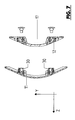
- the projections 27 and 28 are each spaced apart in the direction of the Y-axis, with a distance which is greater than the outer diameter of the pins 16. Furthermore, all the projections 27 and 28 are arranged in a common YZ plane and at their free Ends arranged knife edge like incoming, lying with the cutting edge in the YZ plane. The arrangement and length of the projections 27 and 28 is further selected so that, with the upper part 11 fitted on the upper part 11, each pin 16 extends through the space or gap between two projections 27 and 28.
- each pin 29 in a hollow pin 20 each pin 30 in a Hollow pin 21 and each pin 31 engages in a hollow pin 22 of the lower part.
- the final securing of the upper part 11 on the lower part 12 then takes place, for example, by screwing and / or latching.
- For screwing are each provided with a nut threaded piece 32 made of metal in the pin formed as a hollow pin 32, which is anchored in these pins, for example by pressing and into which a bore in the wall 18 by cross-bolt 33 can be screwed.
- the corresponding pins for example, in turn, the pins 29 and 20 or other cooperating pin of the upper part 11 and the lower part 12 are provided with corresponding locking elements 34 and 35, preferably as prefabricated components with the upper part 11 and lower part 12th be connected after injection molding. Combinations of screw and locking connections are possible. Furthermore, it is possible in the end piece to provide both screw and locking connections between the upper part 11 and the lower part 12.
- a tab 36 is provided, which is fastened at both ends at the rear end of the end piece 10, ie at the back 15 by screwing to the lower part 12, in such a way that the tab 36, the channel 17 at the bottom of the End piece 10 bridges.
- the lower part 12 is formed so that the preferably serving as a strain relief tab 36 is flush with its underside with the underside of the lower part 12.
- the lower part 12 For attachment of the end piece 10 at the end of the cover profile 1, the lower part 12 is first inserted with the upper part 11 with the two pins 16 each in a channel 7, so that the lower part 12 with its end face 13 to the end of the cover 1 bluntly connects and all Channels 4 and 5 of the cover 1 in the channel 17 open.
- the positive radial connection between the cover 1 and the lower part 12 is made.
- the upper part 11 is placed on the lower part 12, in such a way that the corresponding pins 20/29, 21/30 and 22/31 interlock and thereby the upper part 11 is guided on the lower part 12.
- the projections 27 and 28 penetrate through the layer 8 in the profile body 2, so then after the complete placement and fixing of the upper part 11 on the lower part 12, the end piece 10 in the axial direction of the X- Axle parallel to the longitudinal extent of the cover or parallel to the axis of the pin 16 is secured to the cover 1 and even at high, exerted on the end piece 10 tensile forces loosening of the end piece 10 from the cover 1 does not occur. Since the two projections 27 and 28 penetrate into the cover 1 in the vicinity of the pin 16, carried by these pins a support of the material of the profile body 2, whereby the complete penetration of the projections 27 and 28 is facilitated.
- the exact position of the lower part 12 with respect to the end of the covering profile 1 is ensured when inserting the pin 16. Furthermore, the radial fixation through the pins 16 has the advantage that the underside of the lower part 12 can lie flush with the underside of the cover profile 1, the cover 1 so also at the transition to the fitting tightly rests on the floor 3.
- interlocking pins 20/29, 21/30 and 22/31 which are oriented with their axes in the Y-axis and thus perpendicular to the axes of the projections or pin 16 is not only an unambiguous position of the upper part 11 on the Lower part 12 defines, but it is also necessary for the positive connection between the end piece and the cover profile form-fitting connection achieved between the upper part 11 and the lower part 12. Furthermore, there is a guide of the upper part 11 on the lower part 12 when pressing the projections 27 and 28 in the profile body. A lateral deflection of the upper part 11 during impressions is thus avoided.
- the center plane M2 is identical to the center plane M2.
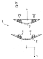
- the end piece can also be designed as a connecting piece between two adjoining cover profiles 1, in particular in the form that the end piece 10a forms a joint, with which the adjoining one and the end piece 10a interconnected cover profiles 1 in the non-use state can be folded on each other, in such a way that these profiles then zigzag or accordion-like, for example, for transport and / or storage purposes.
- the cover profiles 1 connected to each other via one or more end pieces 10a are then replaced arranged so that they connect again on a ground or ground.
- the connecting piece 10a consists, for example, of two connecting pieces 10 which are connected to one another via a suitable articulated connection, for example via a hinge connection 37 having two articulated levers 37.1.
- articulated levers 37.2 which are pivotally mounted at both ends inside the closed end piece 10, again about axes perpendicular to the longitudinal extension of the cover profiles 1 and parallel to the underside of the connecting pieces 10 and parallel to the plane of the floor or ground.
- the two articulated levers 37.2 are e.g. made of plastic and provided at its ends with an integrally formed pivot pin 38 or formed, which is in each case one, for example, in the lower part 12 formed on the inside of the respective end piece 10 and stored in a schematically indicated in Figure 12 with 39 bearing opening.
- openings 40 are provided in the connecting pieces, which are open at the top, on the underside and on the mutually facing rear sides of the connecting pieces 10 and in which the articulated levers 37.2 are each accommodated with a partial length when covering profiles 1 resting on a floor or underground.
- the openings 40 are formed by corresponding recesses in the upper part 11 and in the lower part 12. Since the articulated levers 37.2 are each received with a partial length in a recess or opening 40, results within these recesses a lateral support for the articulated lever 37.2 and thus improved stability for the end piece 10a in the use case.
- the connecting pieces 10 may be expedient for the connecting pieces 10 not to be at their rear side facing away from the respective covering profile 1, as in FIG. 12 illustrated, convex, but concave, as indicated in the figure 12 with the broken lines 41, so as to achieve a clearance for the recorded in the cover profiles and extending over the end piece 10a lines 6 after folding the cover profiles 1.
- the channel 17 extending in the direction of the x-axis is open at the underside of the lower part 12 and thus also at the bottom of the end piece 10 fastened to the respective covering profile 1, so that the lines 6 at the bottom of the Abdrückprofils 1 and the end pieces 10 and 10a ago can be inserted.
- the lines 6 are then held in the local channels 4 and 5 characterized in that these channels are accessible at the bottom of the cover only through slots, the side of tongues from the elastic material of the cover or from the material of the layer 8.1 are limited.
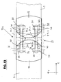
- FIGS. 13-16 show, as a further embodiment, an end piece 1b, which in turn is essentially formed in two parts from the upper part 11b and the lower part 12b and essentially differs from the end piece 10 only in that the lower part 12b in the region of the channel 17 is closed to receive the lines 6 at the bottom.
- the assembly of the end pieces 10 b is then carried out at the ends of the cover 1 in the form that after inserting the lines into the channels 4 and / or 5 of the cover 1, the lower part 12 b at the respective end of the cover 1 by inserting the pin 16 in the channels 7 is attached, so that the lines 6 are accommodated in the closed at the bottom of the lower part 1 2b channel 17.
- the upper part 11 b is placed and fixed to the lower part 12 b, for example by screwing with the screws 33 or by locking.
- the projections 27 and 28 in the material of the cover and thereby fix the end piece 10b on the cover.
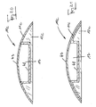
- FIGS. 17-21 show, as a further embodiment, a covering profile 43 which completely corresponds to the covering profile 1 or the profile body 2 of the material and the properties of its profile body 44 and, like the profile body 2, to the covering profile upper layer 8 and FIG the covering profile bottom forming layer 8.1 is provided.
- the cover profile 43 differs from the cover profile 1 but by enlarged dimensions, i. in particular by a greater width perpendicular to the profile longitudinal direction.
- the cover profile 43 differs from the cover profile 1 but in that instead of the channels 5 and 6 of the Abdeckprofiloberseite accessible channels 45 are provided for receiving the lines 6 and these channels closed by a in the longitudinal direction of the cover 43 extending, strip-like cover 46 are.
- the cover 46 is made of plastic, preferably of the plastic material of the layer 8, and is held along its longitudinal edges 46.1 by latching on the profile body 44. To relieve the cover 46, this protects with its underside on webs 44.1, which are formed between the channels 46 on the profile body 44.
- the particular for this cover profile end pieces are designed so that the insertion of the lines 6 in the open end piece can also be done from above, ie suitable for the cover basically end pieces, which are formed according to the end piece 10b, but Of course, in the dimensions of the dimension, in particular width and height of the cover 43 are adjusted.
- an end piece 10c which allows the insertion of the lines 6 from above and is formed in three parts, consisting of a cap-like upper part 11c, a lower part 12c and an additional cover 47, which u.a. the channel 17 and the lower part 12c covering where this lower part is not already covered by the upper part 11 c, i. in particular on the cover profile 43 facing away from the back of the cover profile 43 adapted end piece 10c. It is understood that the end piece 10c is again adapted to the cross section of the cover 43.
- the channel 17, which is open towards the top of the end piece 10c, is provided in the upper part in this embodiment, in that the upper part 11c is trough-like in a central region 49, i.e., in the upper part. is designed as a top and front and back open tub.
- This embodiment offers the possibility of preassembling or prefabricating the cover profiles 43 at both ends or else only at one end with an end piece 10c and deliver them in this form and / or ready for use, in which case the covers 46 and 47 are removed Lines inserted into the channels 45 and 17 and thereafter these channels are closed by the lid 46 and 47, respectively.
- the lower part 12 c For the connection of the end piece 10 c with the respective end of the cover profile 43, the lower part 12 c, for example, in turn, provided with the pins 16, which engage in the additional channels 7 corresponding channels 49.
- the upper part 11 c is designed so that it overlaps the transition between the lower part 12 c and the cover profile 43 after assembly, ie this projecting beyond the cover profile adjacent end face of the lower part 12 c.
- the projections 27 and 28 are provided, which engage in the material of the cover 34.
- the attachment of the upper part 11c and the lower part 12c at the respective end of the cover 43 can also on other ways, but in any case such that all channels 45 open into the channel 17.
- connection between the upper part 11c and the lower part 12c takes place, for example, by latching using molded-on latching elements or else by connecting elements, for example screws, rivets, etc., or by gluing or welding.
- the lid 47 is held by latching or by conventional fasteners, such as screws, etc. on the upper part 11c and lower part 12c.
- the upper part 11c extends only over a part of the length formed between the front side and the rear side of the end piece 10c, as indicated in FIG. 17 by the broken line 11c.1.
- the advantage of this embodiment described in connection with FIGS. 17-21 is, inter alia, in that for inserting the lines 6, the cover profile 43 does not have to be turned.
- the end piece 10 c may be formed as well as the end piece 10 b with a strain relief 36.
- the invention has been described above by means of exemplary embodiments. It is understood that numerous changes and modifications are possible without thereby departing from the idea underlying the invention.
- the axial fixation of the end piece does not take place through the upper part, which is placed on a radially fixed to the cover lower part of this guided, but by another element, which by penetration into the material of the cover 1 in a Axial direction radially or approximately radially to the longitudinal extension of this profile, the connection piece on the cover also secures axially.
- the radial fixation of the end piece can also be done differently than described above, for example, characterized in that the projections or pins 16 are tapered running, so that they can be pressed without the prepared channels 7 in the profile body 2.
Landscapes
- Engineering & Computer Science (AREA)
- Architecture (AREA)
- Civil Engineering (AREA)
- Structural Engineering (AREA)
- Installation Of Indoor Wiring (AREA)
- Connector Housings Or Holding Contact Members (AREA)
- Details Of Indoor Wiring (AREA)
Applications Claiming Priority (2)
| Application Number | Priority Date | Filing Date | Title |
|---|---|---|---|
| DE102005049967 | 2005-10-19 | ||
| DE102006048474A DE102006048474B4 (de) | 2005-10-19 | 2006-10-11 | Abschlussstück |
Publications (1)
| Publication Number | Publication Date |
|---|---|
| EP1777791A2 true EP1777791A2 (fr) | 2007-04-25 |
Family
ID=37814045
Family Applications (1)
| Application Number | Title | Priority Date | Filing Date |
|---|---|---|---|
| EP06021384A Withdrawn EP1777791A2 (fr) | 2005-10-19 | 2006-10-12 | Pièce de finition et/ou de liaison |
Country Status (2)
| Country | Link |
|---|---|
| EP (1) | EP1777791A2 (fr) |
| DE (1) | DE102006048474B4 (fr) |
Families Citing this family (4)
| Publication number | Priority date | Publication date | Assignee | Title |
|---|---|---|---|---|
| DE102011014716B4 (de) * | 2011-03-23 | 2013-01-17 | Volkswagen Aktiengesellschaft | Formkörperanordnung und Verfahren zur Herstellung einer Formkörperanordnung |
| DE102012006057B4 (de) * | 2012-03-27 | 2016-06-02 | Kaiser Gmbh & Co Kg | Installationsdose für elektrotechnische Anwendungen |
| DE202013104937U1 (de) * | 2013-11-05 | 2015-02-06 | Helmut Hiendl | Abdeckelement für Leitungen |
| DE102015006502A1 (de) | 2015-05-22 | 2016-11-24 | race result AG | Aufbodenkanal |
Citations (1)
| Publication number | Priority date | Publication date | Assignee | Title |
|---|---|---|---|---|
| DE10148937A1 (de) | 2001-10-04 | 2003-05-15 | Helmut Hiendl | Abdeckprofil für Leitungen, insbesondere Kabelbrücke |
Family Cites Families (1)
| Publication number | Priority date | Publication date | Assignee | Title |
|---|---|---|---|---|
| DE19653016A1 (de) * | 1996-07-31 | 1998-07-02 | Rolec Gehaeusesysteme Rose & R | Gelenkelement für ein Tragarmsystem |
-
2006
- 2006-10-11 DE DE102006048474A patent/DE102006048474B4/de active Active
- 2006-10-12 EP EP06021384A patent/EP1777791A2/fr not_active Withdrawn
Patent Citations (1)
| Publication number | Priority date | Publication date | Assignee | Title |
|---|---|---|---|---|
| DE10148937A1 (de) | 2001-10-04 | 2003-05-15 | Helmut Hiendl | Abdeckprofil für Leitungen, insbesondere Kabelbrücke |
Also Published As
| Publication number | Publication date |
|---|---|
| DE102006048474A1 (de) | 2007-04-26 |
| DE102006048474B4 (de) | 2011-07-07 |
Similar Documents
| Publication | Publication Date | Title |
|---|---|---|
| WO2018210892A1 (fr) | Passage de câble | |
| DE29517590U1 (de) | Kettenförderer mit verbesserten Gleiteigenschaften | |
| DE102020204526A1 (de) | Vorrichtung zur Durchführung und Zugentlastung von Strängen | |
| DE29722507U1 (de) | Kugelschale für ein Kugelgelenk und Kugelgelenk mit einer solchen Kugelschale | |
| EP3452667B1 (fr) | Caniveau de drainage superficiel avec une paroi frontale | |
| EP2054638B1 (fr) | Clip de fixation | |
| EP3851686B1 (fr) | Dispositif de fixation léger | |
| EP3557084A1 (fr) | Élément de raccordement permettant de raccorder des éléments profilés | |
| DE2903960B2 (de) | Vollisolierte Abzweigklemme | |
| EP2994650B1 (fr) | Élément de fixation pour la connection d'un support de transmission à un élément de levier | |
| DE102006048474B4 (de) | Abschlussstück | |
| EP0579125B1 (fr) | Raccord à vis en matière plastique pour entrée et traversée de paroi, étanchéité et décharge de traction de câbles, conduits ou tuyaux souples | |
| EP1862356A1 (fr) | Clip de fixation | |
| DE19950812A1 (de) | Tülle mit Verbindungsabschnitt | |
| EP2347138B1 (fr) | Dispositif pour raccorder des tubes profilés | |
| DE4435281C2 (de) | Isolierstab aus Kunststoff hoher Festigkeit zur gegenseitigen Verbindung zweier Metallprofile zu einem Verbundprofil | |
| DE102009021840B3 (de) | Lageranordnung für eine Blattfeder aus einem Faserverbundwerkstoff | |
| DE69909666T2 (de) | Vorrichtung zum Verbinden des Ankerkerns eines elastischen Gelenks mit einem Aussenteil | |
| DE3715529C2 (fr) | ||
| DE3422926C2 (de) | Kugelpfanne für ein Winkelkugelgelenk | |
| DE102018108402B4 (de) | Verbindungssteckteil für einen Felgenring, insbesondere für Fahrräder | |
| DE202015002097U1 (de) | Energieführungskette | |
| EP0142656B1 (fr) | Appareil pour lier un objet oblong, par example des câbles | |
| DE10032638C2 (de) | Vorrichtung zur Halterung einer Leiste an einem Träger | |
| EP2803533B1 (fr) | Dispositif destiné à agencer une barre présentant un canal longitudinal sur un support |
Legal Events
| Date | Code | Title | Description |
|---|---|---|---|
| PUAI | Public reference made under article 153(3) epc to a published international application that has entered the european phase |
Free format text: ORIGINAL CODE: 0009012 |
|
| AK | Designated contracting states |
Kind code of ref document: A2 Designated state(s): AT BE BG CH CY CZ DE DK EE ES FI FR GB GR HU IE IS IT LI LT LU LV MC NL PL PT RO SE SI SK TR |
|
| AX | Request for extension of the european patent |
Extension state: AL BA HR MK YU |
|
| STAA | Information on the status of an ep patent application or granted ep patent |
Free format text: STATUS: THE APPLICATION IS DEEMED TO BE WITHDRAWN |
|
| 18D | Application deemed to be withdrawn |
Effective date: 20090505 |