EP1777851A2 - Appareil-multi-indication pour l'évaluation de signaux vidéo distribuées par le protocole Internet - Google Patents
Appareil-multi-indication pour l'évaluation de signaux vidéo distribuées par le protocole Internet Download PDFInfo
- Publication number
- EP1777851A2 EP1777851A2 EP06254804A EP06254804A EP1777851A2 EP 1777851 A2 EP1777851 A2 EP 1777851A2 EP 06254804 A EP06254804 A EP 06254804A EP 06254804 A EP06254804 A EP 06254804A EP 1777851 A2 EP1777851 A2 EP 1777851A2
- Authority
- EP
- European Patent Office
- Prior art keywords
- circuit
- signal level
- signal
- broadband
- signals
- Prior art date
- Legal status (The legal status is an assumption and is not a legal conclusion. Google has not performed a legal analysis and makes no representation as to the accuracy of the status listed.)
- Withdrawn
Links
- 238000005259 measurement Methods 0.000 claims abstract description 178
- 238000012360 testing method Methods 0.000 claims abstract description 117
- 238000004891 communication Methods 0.000 claims abstract description 72
- 238000012545 processing Methods 0.000 claims abstract description 40
- 230000008878 coupling Effects 0.000 claims abstract description 20
- 238000010168 coupling process Methods 0.000 claims abstract description 20
- 238000005859 coupling reaction Methods 0.000 claims abstract description 20
- 239000000835 fiber Substances 0.000 claims abstract description 14
- 230000005540 biological transmission Effects 0.000 claims description 21
- 238000011144 upstream manufacturing Methods 0.000 description 65
- 238000000034 method Methods 0.000 description 34
- 238000006243 chemical reaction Methods 0.000 description 25
- 230000003287 optical effect Effects 0.000 description 24
- 230000008569 process Effects 0.000 description 19
- 238000004458 analytical method Methods 0.000 description 14
- 238000010586 diagram Methods 0.000 description 11
- 238000013461 design Methods 0.000 description 8
- 230000006870 function Effects 0.000 description 7
- 230000004044 response Effects 0.000 description 7
- 238000001228 spectrum Methods 0.000 description 6
- 238000012384 transportation and delivery Methods 0.000 description 6
- 230000008901 benefit Effects 0.000 description 5
- 238000012937 correction Methods 0.000 description 5
- 230000003321 amplification Effects 0.000 description 4
- 238000004364 calculation method Methods 0.000 description 4
- 230000003111 delayed effect Effects 0.000 description 4
- 238000003199 nucleic acid amplification method Methods 0.000 description 4
- 238000005516 engineering process Methods 0.000 description 3
- 238000011056 performance test Methods 0.000 description 3
- 238000005070 sampling Methods 0.000 description 3
- 230000011664 signaling Effects 0.000 description 3
- 101001091379 Homo sapiens Kallikrein-5 Proteins 0.000 description 2
- 102100034868 Kallikrein-5 Human genes 0.000 description 2
- 230000003044 adaptive effect Effects 0.000 description 2
- 230000002457 bidirectional effect Effects 0.000 description 2
- 230000033228 biological regulation Effects 0.000 description 2
- 230000001419 dependent effect Effects 0.000 description 2
- 230000000694 effects Effects 0.000 description 2
- 239000000284 extract Substances 0.000 description 2
- 238000012012 milestone trend analyses Methods 0.000 description 2
- 238000012986 modification Methods 0.000 description 2
- 230000004048 modification Effects 0.000 description 2
- 230000008447 perception Effects 0.000 description 2
- 230000005236 sound signal Effects 0.000 description 2
- 230000001960 triggered effect Effects 0.000 description 2
- 230000000007 visual effect Effects 0.000 description 2
- VOWAEIGWURALJQ-UHFFFAOYSA-N Dicyclohexyl phthalate Chemical compound C=1C=CC=C(C(=O)OC2CCCCC2)C=1C(=O)OC1CCCCC1 VOWAEIGWURALJQ-UHFFFAOYSA-N 0.000 description 1
- 230000006978 adaptation Effects 0.000 description 1
- 230000000903 blocking effect Effects 0.000 description 1
- 239000000969 carrier Substances 0.000 description 1
- 230000001427 coherent effect Effects 0.000 description 1
- 230000001627 detrimental effect Effects 0.000 description 1
- 238000003745 diagnosis Methods 0.000 description 1
- 238000002405 diagnostic procedure Methods 0.000 description 1
- 230000009977 dual effect Effects 0.000 description 1
- 238000001914 filtration Methods 0.000 description 1
- 230000003993 interaction Effects 0.000 description 1
- 238000007726 management method Methods 0.000 description 1
- 238000003012 network analysis Methods 0.000 description 1
- 238000012372 quality testing Methods 0.000 description 1
- 238000013139 quantization Methods 0.000 description 1
- 238000009877 rendering Methods 0.000 description 1
- 239000004065 semiconductor Substances 0.000 description 1
- 238000004088 simulation Methods 0.000 description 1
- 238000010183 spectrum analysis Methods 0.000 description 1
- 238000013179 statistical model Methods 0.000 description 1
- 230000001629 suppression Effects 0.000 description 1
- 208000024891 symptom Diseases 0.000 description 1
- 238000012546 transfer Methods 0.000 description 1
- 238000013024 troubleshooting Methods 0.000 description 1
Images





Classifications
-
- H—ELECTRICITY
- H04—ELECTRIC COMMUNICATION TECHNIQUE
- H04N—PICTORIAL COMMUNICATION, e.g. TELEVISION
- H04N7/00—Television systems
- H04N7/16—Analogue secrecy systems; Analogue subscription systems
- H04N7/173—Analogue secrecy systems; Analogue subscription systems with two-way working, e.g. subscriber sending a programme selection signal
- H04N7/17309—Transmission or handling of upstream communications
-
- H—ELECTRICITY
- H04—ELECTRIC COMMUNICATION TECHNIQUE
- H04B—TRANSMISSION
- H04B3/00—Line transmission systems
- H04B3/02—Details
- H04B3/46—Monitoring; Testing
-
- H—ELECTRICITY
- H04—ELECTRIC COMMUNICATION TECHNIQUE
- H04H—BROADCAST COMMUNICATION
- H04H20/00—Arrangements for broadcast or for distribution combined with broadcast
- H04H20/12—Arrangements for observation, testing or troubleshooting
-
- H—ELECTRICITY
- H04—ELECTRIC COMMUNICATION TECHNIQUE
- H04N—PICTORIAL COMMUNICATION, e.g. TELEVISION
- H04N17/00—Diagnosis, testing or measuring for television systems or their details
- H04N17/004—Diagnosis, testing or measuring for television systems or their details for digital television systems
-
- H—ELECTRICITY
- H04—ELECTRIC COMMUNICATION TECHNIQUE
- H04N—PICTORIAL COMMUNICATION, e.g. TELEVISION
- H04N21/00—Selective content distribution, e.g. interactive television or video on demand [VOD]
- H04N21/40—Client devices specifically adapted for the reception of or interaction with content, e.g. set-top-box [STB]; Operations thereof
- H04N21/41—Structure of client; Structure of client peripherals
- H04N21/4104—Peripherals receiving signals from specially adapted client devices
- H04N21/4122—Peripherals receiving signals from specially adapted client devices additional display device, e.g. video projector
-
- H—ELECTRICITY
- H04—ELECTRIC COMMUNICATION TECHNIQUE
- H04N—PICTORIAL COMMUNICATION, e.g. TELEVISION
- H04N21/00—Selective content distribution, e.g. interactive television or video on demand [VOD]
- H04N21/40—Client devices specifically adapted for the reception of or interaction with content, e.g. set-top-box [STB]; Operations thereof
- H04N21/43—Processing of content or additional data, e.g. demultiplexing additional data from a digital video stream; Elementary client operations, e.g. monitoring of home network or synchronising decoder's clock; Client middleware
- H04N21/442—Monitoring of processes or resources, e.g. detecting the failure of a recording device, monitoring the downstream bandwidth, the number of times a movie has been viewed, the storage space available from the internal hard disk
- H04N21/44209—Monitoring of downstream path of the transmission network originating from a server, e.g. bandwidth variations of a wireless network
Definitions
- the present addresses the above need, as well as others, by providing a combination video stream analyzer and physical layer test device that performs tests relating to the quality of video stream service (packet loss, video stream bit rate, delay and/or jitter) as well as signal level measurements and related physical layer measurements.
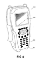
- the device is preferably embodied in a handheld, portable device.
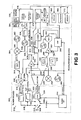
- Fig. 1 shows an exemplary test configuration that employs an analysis device 100 according to the present invention within a communication network 110.
- the communication network 110 is a land-based broadband network typically known as a cable network.
- the communication network 110 is a hybrid fiber coax or HFC network that employs both fiber optic links and coaxial cable to effect radio frequency communications between a plurality of subscribers and a network headend 112.
- the network headend 112 is further operable to provide Internet communications between a plurality of subscribers and one or more devices 152 connected to the Internet 150.
- the devices 152 are external to the communication network 110.
- the analysis device 100 is operable to test multiple parameters of the network, including by way of example, the signal strength at a remote location of the network 110, whether Internet connectivity is available at remote locations of the network 110, and/or digital channel quality at remote locations of the network 110.
- the precise combination of features in the analysis device 100 may vary from embodiment to embodiment.
- the communication network 110 includes a headend 112, a fiber plant 114, a coaxial cable plant 116, and a plurality of network tap lines 118, a plurality of subscriber drop lines 120, a plurality of subscriber sites 122.
- a headend optical encoder/decoder 124 connects the network headend 112 to the fiber plant 114
- node optical encoder/decoders 126 connect the fiber plant 114 to the coaxial cable plant 116.
- the fiber plant 114 is used as a dedicated line that provides communication between discrete portions of the network 110 and the headend 112.
- the coaxial cable plant 116 is used to distribute network communication line within each discrete portion of the network 110.
- the source of broadcast program information 132 may suitably be any well known device or set of circuits that obtain broadcast audio and/or visual information for broadcast over the network 110.
- the source of broadcast program information 132 generally provides local television channels, subscription television channels, pay and free audio channels, free non-local television channels, television guide information and the like.
- some subscribers have a television 128 operably connected to the subscriber drop line 120, a cable modem circuit 130 connected to the subscriber drop line 120, or both.
- the analysis device 100 is intended to test or analyze aspects of the performance of the network 110 in a variety of locations, particularly those proximate one or more subscriber premises 122.
- service providers i.e., the party that provides communication services via the network 110
- customer complaints Because the customer can typically only describe visible symptoms of a problem (e.g., cable modem does not connect to the network, slow internet connectivity, fuzzy television picture, etc.), actual diagnosis of the problem often requires testing that is performed at the complaining subscriber's premises.
- the analysis device 100 may be connected directly to the subscriber coax drop line 120, or may be connected to the drop line 120 through a cable modem 130 via Ethernet or otherwise. As discussed below, many of the tests performed by the test device are performed through the direct connection to the subscriber coax drop line.
- the audio-visual baseband information for each broadcast channel is modulated onto a particular channel frequency carrier and then combined with all of the other channel frequency carriers to form a multichannel broadband RF signal.
- the broadband RF signal is provided to the headend optical encoder/decoder 124.
- the headend optical encoder/decoder 124 converts the broadband RF signal to an optical signal, which then propagates through the fiber plant 114 to the nodes 126.
- the nodes 126 convert the optical signal back to a broadband RF signal and then provide the broadband RF signal to the lines of the cable plant 116.
- the cable plant 116, the network tap lines 118, and the subscriber drop lines 120 cooperate to provide the broadband RF signal to each subscriber premise 122. If the subscriber premise 122 has a television 128 operably connected to the drop line 120, then the television 128 may tune and display any of a plurality of audio-visual programs within the broadband RF signal.
- the CMTS 134 prepares upstream packets for transmission over the Internet 150 in accordance with known standards and techniques.
- the CMTS 134 provides the prepared upstream packets to the router 148, which in turn provides the packets to the Internet 150.
- the Internet 150 may then provide the data packets to one or more remote computers 152.
- Such data packets may include electronic mail, http requests, web page information, and any other information normally associated with Internet usage. Packets of data generated by remote computers 152 may be transmitted to a cable modem 130 of the network using a reverse path. VoIP and video services also use the same path.
- the analysis device 100 also preferably includes a display 214.
- the display 214 is preferably a user-readable display for displaying analysis information.
- the display 214 may also be employed to illustrate user options or choices.
- the display 214 may incorporate touch screen technology to allow input to the device 100 directly through the display 214. In such a case, the display 214 would also comprise a portion of the input 210.
- the display 214 may suitably be an LCD display, a cathode-ray tube display, a plasma display, or other type of display.
- other elements that provide output in human-perceivable forms, such as audio systems or the like, may be used instead of, or in addition to, the display.
- a single device having the components described above that operate in a manner set forth below may be used to generate data and measurements useful for analyzing the quality of service over a normal broadcast communication system.
- the diagnostic data that may be generated by the processing circuit are especially useful for evaluating the quality of VoIP and video service quality obtained over the cable network connections.
- the downstream filter 324 is configured to pass RF signals within the frequency band 88 MHz to 860 MHz (108 MHz to 862 MHz in Europe) and block signals within the band of approximately 5 MHz and 42 or 65 MHz.
- the upstream filter 322 may be a suitable low pass filter with a cut-off frequency in the vicinity of about 55-70 MHz
- the downstream filter 324 may be a high pass filter with a cut-off frequency in the vicinity of 75-80 MHz.
- the upstream filter 322 is disposed between the shared signal line 318 and the upstream input 316.
- the RF switch 310 is preferably a double pole, double throw switch that has a first position and a second position. In the first position, the RF switch 310 connects the RF I/O 309 directly to the frequency conversion circuit 308. In the second position, the RF switch 310 connects the RF I/O 309 to the shared signal line 318, and connects the downstream output 320 to the frequency conversion circuit 308.
- the control interface 314 is an interface circuit, such as a serial/parallel interface (SPI) circuit that receives control signals relating to the operation of the tuning circuit 302 and includes the logic to provide the signals to the controlled devices within the tuning circuit 302.
- the control interface 314 receives signals that control the frequency conversion circuit 308 and the RF switch 310. Responsive to such signals, the control interface 314 provides signals to the control input 308a that cause the frequency conversion circuit 308 to tune to a specified frequency channel, and/or cause the RF switch 310 to be in a select one of the first and second positions.
- the control interface 314 is operably connected to receive control signals from the SLM digital signal processor 366 of the measurement circuit 304, discussed further below.
- the outputs of the output filter 344 and the modem circuit 332 are connected to selectable inputs of an output RF switch 346.
- the RF switch 346 is controllable to provide a select connection to either the output filter 344 or the modem circuit 332.
- the output of the RF switch 346 is connected to a signal input of the output amplifier 348.
- the output amplifier 348 includes a control input 348a connected to the modem circuit 332.
- the control input 348a is used to adjust the amplification level provided by the output amplifier 348.
- the connections to the modem circuit 332 include an IF input 424, which is connected to the QAM receiver 410, a receiver control output 426, which is connected to the QAM receiver 410, an RF output 428 and a transmitter control output 430, both of which are connected to the QAM modulator or transmitter 412, control/test data outputs 432 and 434, which are connected to the USB transceiver 418 and the RS-232 transceiver 420, respectively.
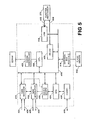
- the CPU 408 is a high speed processing circuit that controls the operations of the modem circuit 332.
- the CPU 408 is operable to obtain information from and provide control information to the DOCSIS modem 402, the MTA 404, the QAM receiver 410, and the QAM transmitter 412.
- the CPU 408 is operable to exchange data with external components via the ports 432 and 434 via the USB transceiver 418 and the RS-232 transceiver 420.
- the Broadcom BCM3352 Reference Design available from Broadcom Corporation, includes source code for the CPU 408 that may be modified to adjust the operations of the various elements of the modem circuit 332. As discussed below, certain data obtained within the CPU 408 may be used in the performance of one or more system diagnostic tests.
- the external bus interface (EBI) 414 provides an interface to an external bus to which program flash memory 442 may be connected.
- the program flash memory 442 is used to store program code for the CPU 408.
- the gain adjustment amplifier 362 is configured to provide a variable amount of gain to the filtered IF signal provided to it through the switch 360.
- the gain adjustment amplifier 362 includes a control input 362a in which it receives a gain control signal from the DSP 366, as discussed further below.
- the gain adjustment amplifier 362 is operably connected to provide its output signal to the ADC 364.
- the ADC 364 is operable to generate digital samples of the filtered and gain-adjusted IF signal and provide those samples to the DSP 366. Such ADCs are known.
- the ADC 364 should be able to sample at rates between 1.04 and 3.29 million of samples per second.
- the ADC clocking circuit 368 provides the clock signal that controls the sampling rate of the ADC 364 based on the input signal being sampled.
- the DSP 366 controls the tuner 302 to provide the controls that select the channel to be "tuned to", or in other words, the channel frequency to be converted by the frequency conversion circuit 308 that is centered about the IF.
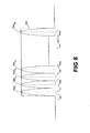
- the DSP 366 controls the SLM oscillator 355 to select the portion of the channel to be measured. In particular, to obtain signal level measurements on a digital channel, several 330 kHz bands of the channel are measured, and then the overall signal level of the channel may be estimated. Further detail regarding such a measurement is provided further below.
- control/interface circuit 306 is generally operable to allow a technician to select from a plurality of measurement operations, and further provides human perceptible output derived from the measurement operations.
- control/interface circuit 302 in the embodiment described herein includes a control processor 370, a memory 372, a speaker phone circuit 374, a microphone 376, a speaker 378, a keypad 380, a display 382, and an external interface port 384.
- the speaker phone integrated circuit (IC) 374 performs audio duplexing, feedback suppression, amplification and other operations normally associated with speaker-telephones.
- the speaker phone IC 374 which is suitably an MC34018DW integrated circuit package available from Motorola Corporation, is operable to receive analog audio signals from the modem circuit 332 and provide amplified analog signals to the speaker 378.
- the speaker phone chip 374 is further operable to bias the microphone 376 and receive microphone signals therefrom.
- the speaker phone chip 374 is operable to provide the microphone signals to the modem circuit 332.
- the DSP 366 provides to the control interface 314 of the tuner circuit 302, a tuning control signal that corresponds to the channel N (block 510).
- the control interface 314 provides appropriate control signals to the frequency conversion circuit 308 to cause the frequency conversion circuit to tune to the channel frequency f N .
- a signal is a signal that causes a local oscillator within the frequency conversion circuit 308 to provide a particular local oscillator (LO) frequency corresponding to the channel frequency f N .
- LO local oscillator
- Other known methods may be used.
- the DSP 366 may further provide a control signal to the control interface that causes the switch 310 to provide a direct connection between the input 309 and the frequency conversion circuit 308.
- the DSP 366 (block 520) obtains the synchronization pulses within the vertical interval of the television signal on channel N using the received sampled IF. Identification of the synchronization pulses may involve determining the largest magnitude samples that form a repeating pattern that corresponds to the field frequency of the television signal.
- the DSP 366 may employ any of a number of synchronization pulse identification techniques known in the art.
- Another operation of the device 300 is digital channel SLM.
- one measure of HFC system operation is the signal level of digital television signals, or even digital data signals such as those that carry Internet data packets.
- performing digital channel SLM is useful for evaluating digital cable service.
- the measurements ensure the quality of the physical plant signal path to each customer.
- the measurements may be used to troubleshoot problems on a particular channel or set of channels.
- the device 300 is connected to a customer drop line (such as drop line 120 of Fig. 1), or within the actual premises of the customer.
- a technician couples the RF I/O 309 to a coaxial cable termination in the HFC or cable system. The technician may then select to measure a particular channel by selecting the digital channel signal level measurement option via the display 382 and keypad 380, and then selecting the channel to be measured by either entering the channel number or the frequency number.
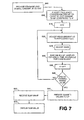
- the DSP 366 provides to the control interface 314 of the tuner circuit 302, a tuning signal that corresponds to the channel N (block 610).
- the control interface 314 provides appropriate control signals to the frequency conversion circuit 308 to cause the frequency conversion circuit to tune to the channel frequency f N in a manner similar to the one discussed above (block 510, Fig. 6).
- the DSP 366 may further provide a control signal to the control interface that causes the switch 310 to provide a direct connection between the input 309 and the frequency conversion circuit 308.
- the DSP 366 adjusts the gain of the gain adjustment amplifier 362 such that the samples generated by the ADC 364 are within a good operating window of the dynamic range of the ADC 364 (block 625). Thus, DSP 366 uses the received samples to determine the appropriate adjustment. The adjustment may occur in the sequence shown in Fig. 7 or at some other part of the process.
- the control processor 370 sends a command signal to the CPU 408 to perform a physical layer test to the DOCSIS modem 402 (block 805).
- the control processor 370 provides the command signal through the RS-232 connection 434 or the USB connection 432.
- the RS-232 transceiver 420 or the USB receiver 418 propagates the command signal over the bus 416 to the CPU 408.
- the physical layer test involves the initial portion of the connection of the DOCSIS modem 402 to the CMTS of the system. This initial portion of such a connection is known in the art as ranging.
- a DOCSIS modem ranging operation is discussed in more detail below (blocks 810 to 820).
- the CPU 408 continues the ranging operation by synchronizing the DOCSIS modem 402 with the clock of the CMTS 134 (Block 815). Such operations are also known, and are preconfigured in the BCM3352 modem circuit.
- the CPU 408 also performs operations with the elements of the modem circuit 332 and output amplifier 348 (via control input 348a) to acquire an upstream channel and determine the appropriate modulation type (QPSK or QAM) and the amplification necessary to achieve adequate transmission quality for the channel and modulation type (block 820).
- Such operations are also known, and are preconfigured in the BCM3352 modem circuit.
- Fig. 10 shows an exemplary set of operations that may be used to perform a set of IP layer tests for determining the connectivity of a DOCSIS modem.
- the device 300 attempts to establish modem registration of the DOCSIS modem 402 on the system under test at a location on the network.
- the device 300 obtains and displays various IP connection related values that provide an indication as to whether various elements that are necessary to establish an IP connection are functioning. If the test provides expected results, then the IP connection to the DOCSIS modem 402 is presumably functioning.
- the control processor 370 sends a command signal to the CPU 408 to perform a modem registration test with the DOCSIS modem 402 (block 905). Registration is part of the processing performed by a DOCSIS modem to establish an Internet Protocol layer connection with a CMTS of an HFC or other cable network.
- the control processor 370 provides the command signal through the RS-232 connection 434 or the USB connection 432.
- the RS-232 transceiver 420 or the USB receiver 418 propagates the command signal over the bus 416 to the CPU 408.
- the CPU 408 causes the elements of the modem circuit 332 to perform a ranging operation (block 910) similar to that discussed above (blocks 810, 815 and 820 of Fig. 9).
- the CPU 408 (and control processor 370) may optionally cause display of the physical layer characteristic as noted above (blocks 825, 830 and 835 of Fig. 9). If ranging fails, the CPU 408 and control processor 370 may cooperate to communicate information regarding the failure via the display 382 as discussed above in connection with Fig. 9.
- the CPU 408 continues with the registration process by obtaining an IP address from the headend network 112, and in particular, the DHCP 144, which assigns IP addresses as is known in the art (block 915).
- the CPU 408 and the DOCSIS modem 402 cooperate as is known in the art to generate a request for an IP address and connection to the Internet 150, or at least to the local headend network 138.
- the request is in the form of one or more standard Ethernet packets with appropriate header information and format for communication via the Internet 150.
- the QAM transmitter 412 receives the data packets and modulates the data packets in accordance with the frequency and modulation type defined during ranging (block 910).
- the modulated data packet signal propagates onto the system 110 at the customer premise 122.
- the modulated signal propagates upstream through the associated subscriber drop line 120, the network tap line 118, and the cable plant 116 to the node 126.
- the node converts the RF signal to an optical signal and provides the signal to headend optical/RF converter 124.
- the headend optical/RF converter 124 converts the signal back to an RF signal and provides the signal to the CMTS 134 through the splitter 136.
- the CMTS 134 then cooperates with other elements on the server network 138 (as well as the DOCSIS modem 402) to establish the IP connection with the DOCSIS modem 402.
- the TFTP 140 identifies a configuration file for the DOCSIS modem 402 that identifies its parameters of service
- the TOD server 142 coordinates the time stamp information for packets communicated to and from the DOCSIS modem 402
- the DHCP server 144 assigns an IP address.
- the above described modem registration operations are described in simplified format because they are generally known in the art. Such operations may involve additional upstream and downstream communications between the CMTS 134 and the modem circuit 332.
- the technician may compare the server IP addresses as reported by the CPU 408 with expected values.
- the technician presumably has access to the actual IP addresses of the server network 138, and thus may make a visual comparison.
- the control processor 370 (and/or the memory 372) may be preprogrammed with the actual IP addresses of the various headend servers (i.e. prior to testing), which may then be compared to the "reported" or measured IP addresses of those servers.
- the control processor 370 may cause the display of the results of such a comparison and/or cause the display of both the preprogrammed and the reported IP addresses.
- the display of the name of the configuration file received from the CPU 370 may also be used by the technician to help determine, among other things, the proper location and operation of the TFTP server 140.
- the name of the configuration file can be compared by the technician (or the control processor 370) with the known configuration file name for the DOCSIS modem 402. Again, because the DOCSIS modem 402 is a special test modem in a measurement device 300, the configuration file name should be available through an independent source.
- the Upstream Performance Test (UPT) operation of the measurement device 300 measures several characteristics of the upstream data flow from a DOCSIS cable modem (CM) to the CMTS 134 at the headend of a Hybrid Fiber-Coax CATV network.
- the upstream performance is affected by the RF characteristics of the customer premise service point 122, the ingress characteristics of the rest of the HFC network 110, and the data traffic from other cable modems 130.
- the measurement device 300 can connect directly to the RF coaxial cable at the customer premises 122 or to the data port of the customer cable modem 130, such as an Ethernet port (see Fig. 1).
- the direct connection would be through a communication port that connects directly to the control processor 370 of Fig. 3.
- the control processor 370 performs many of the same upstream data flow tests in either connection mode.
- processor 370 functions as a source of upstream data to be sent through the cable modem 130 attached at the service point being tested.
- processor 370 functions as a data source and also as a cable modem (DOCSIS modem 402) attached at the service point being tested.
- DOCSIS modem 402 cable modem
- the control processor 370 causes ping packets to be sent to the CMTS 134.
- Noise on the upstream channel may corrupt some of these packets and cause them to be unrecognizable at the CMTS 134. Those that reach the CMTS 134 cause it to send an echo reply. Some of these may be corrupted and lost due to noise on the downstream channel.
- the control processor 370 causes pings to load the upstream data flow.
- the CMTS 134 limits the overall throughput of the test cable modem, not just the upstream.
- the UPT In order to get the maximum upstream performance, the UPT must keep downstream loading to a minimum.
- the UPT uses a variation of the standard ICMP echo request that causes large upstream packets to generate small downstream replies. This variant adds extra padding to the upstream request at the Ethernet level, not the ICMP level.
- the CMTS 134 sends replies that match the length of the ICMP request, but do not contain the Ethernet-level padding.
- the BER calculation also requires a statistical estimate of the number of bit errors in a failed packet.
- This processing employs a statistical model of the channel noise distribution obtained from the measured packet error rates.
- the UPT uses SNMP requests to the CMTS to get other performance measures for cable modems in the sample set.
- the CMTS measures and reports the path delay time for each cable modem.
- the UPT requests received byte counts for other cable modems in the sample set periodically. It divides the difference in byte counts by the elapsed time between requests to get the upstream data rate for each cable modem in the sample set.
- the control processor 370 and CPU 408 are also configured to perform downstream Ping and throughput testing.
- the control processor 370 first obtains an IP address and is registered as customer premise equipment. Then the control processor 370 executes a ping test. For a throughput test, the control processor 370 requests a download of a large file stored at the headend 112.
- the CPU 408 communicates the information representative of the measured throughput to the control processor 370.
- the control processor 370 thereafter may cause such information to be displayed on the display 370, and/or may compare the throughput to one or more thresholds.
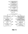
- the measurement device 300 is further operable to provide information to a technician regarding the quality of VoIP service on the network under test (e.g., the network 110 of Fig. 1). In particular, as discussed below, the measurement device 300 displays to the technician various measures of quality of VoIP service including packet loss, delay (or latency), and jitter. An exemplary process for measuring the quality of VoIP service is shown in Fig. 11.
- the modem circuit 332 Responsive to receiving such information, the modem circuit 332 generates a dial tone that propagates through the codec 406 to the speaker phone chip 374.
- the speaker phone chip 374 provides a signal to the speaker 378, which in turn produces an audible dial tone.
- a telephone number is "dialed" (block 1020).
- the CPU 408 notifies the control processor 370, which in turn causes the speaker phone chip 374 to automatically generate the tone dialing sequence of a predetermined telephone number.
- the telephone number may suitably be dialed by the technician using the keypad 380.
- RTCP packets which are control packets of a standard VoIP data stream (block 1030).
- the RTCP packets contain, among other things, information that identifies delay, packet loss and jitter for a defined time period of the call.
- the delay is the average delay in the packets through the HFC system, in other words, between the headend 112 and the DOCSIS modem 402. Because a particular quality of service is expected in telephony service, the delay added by the HFC system is required to be within a certain range.
- Jitter is a measure of the average difference in delay of packets through the system.
- the characteristic of cable telephony is that some packets are delayed more than others. In some cases, the delay differences are such that some packets are received out of order.
- the MTA 404 includes a FIFO-type buffer. The MTA 404 uses the buffer to buffer received packets and allow for longer delayed packets to "catch up". If the delay varies greatly, the buffer may not be large enough to absorb the difference in delay of adjacent data packets, which can result in lost packets. Packet loss is a measure of the number of packets actually lost due to jitter or other problems.
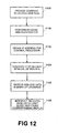
- the CPU 408 cooperates with the DOCSIS modem 402 and the control processor 370 to register the control processor 370 as customer premise equipment (block 1115). Again, details regarding the specifics of registering customer premise equipment are known in the art. As a result of the registration, the control processor obtains an IP address.
- the control processor 370 requests a web site (block 1120).
- the requested website may be entered alphanumerically via the keypad 380, or may be selected from a predetermined list using the keypad 380.
- the control processor 370 in any event generates the IP packet containing an HTTP request for the URL of the desired website.
- the control processor 370 provides an HTTP request to the Internet 150 via the DOCSIS modem 402, the transmitter 412, amplifier 348, diplexer circuit 312, RF I/O 309 and the connected HFC network and headend.
- the website identified by the URL is resident on a computer connected Internet 150, such as one of the computers 152.
- the measurement device 300 is further operable to provide information to a technician regarding the quality of video service on the network under test (e.g., the network 110 of Fig. 1). In particular, as discussed below, the measurement device 300 displays to the technician various measures of quality of video service including packet counts, packet loss, delay (or latency), and jitter. The device 300 may also calculate a stream bit rate and the average packet size.
- the video server 1300 may be coupled to the Internet 150 for testing purposes, preferably the video server 1300 is coupled to the server network 138. Locating the video server at the server network 138 enables the HFC network provider to ascertain whether service quality problems are at the headend, in the physical plant, or at the customer premises. An additional video server on the Internet 150 also enables the provider to determine whether the problem in service quality is on the Internet, rather than being within the service provider's network.
- the device 300 sends server control commands over an upstream channel and collects statistics on the video stream received by the device 300 after the video data packets have been received and decoded as shown in Fig. 13.
- the video stream is implemented in the real time protocol (RTP), although the video stream may also be provided in the real time streaming protocol (RTSP).
- RTP is used to provide test video data packets.
- the transmission of test packets continues until the device 300 sends the server a command to stop or the server sends the device a command to which the device does not respond.
- the commands communicated between the server 1300 and the device 300 are preferably generated and sent in the real time control protocol (RTCP).
- RTCP real time control protocol
- the device 300 monitors a video broadcast that is currently in progress over the network 110 and collects statistics on the packets received and decoded by the device 300.
- An IP video broadcast is preferably implemented with RTSP.
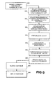
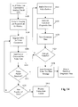
- FIG. 14 An exemplary process for measuring the quality of video service is shown in Fig. 14.
- the process begins with the control processor 370 sending a video test command to the CPU 408 of the modem circuit 332 (block 1400). Such a command is triggered typically by user entry in the keypad 380.
- the CPU 408 cooperates with the other elements of the modem circuit 332 to perform ranging and registration of the DOCSIS modem 402 (block 1404).
- the CPU 408 may suitably perform the relevant ranging and registration processing discussed above with reference to Figs. 10, 11, and 12.
- the CPU 408 and the control processor 370 may suitably cooperate to cause the display of test information derived from the ranging and registration operations as discussed above in connection with Figs. 10 and 11.
- the initial registration and ranging operation involve the communication of a request for a multimedia connection as opposed to an ordinary high speed data IP connection. Such operations are known in the art.
- the BCM3352 circuit is preconfigured to perform such operations.
- the CPU 408 obtains one or more RTP packets from the video data stream (block 1414).
- the CPU 408 generates statistics from the received RTP packets (block 1418). These statistics include the number of packets received, the number of octets received, the number of dropped packets, the number of out-of-sequence packets, the maximum and average jitter, and the round trip delay.
- the CPU 408 may also calculate the stream bit rate, which is preferably expressed in Mbps, and the average packet size.
- the generated and calculated statistics are stored (block 1420) and the CPU 408 determines whether a sufficient sample of video data packets have bee received for the generation of reliable statistics (block 1424).
- DVRs Digital Video Recorders
- Some Digital Video Recorders have a feature commonly known as whole home DVR. This feature allows a user to deliver a video stream being generated at the DVR to another television or display device in the house. This feature enables a user to pause a movie being played in the family room, direct the video stream to the bedroom, and resume watching the movie on a display device in the bedroom).
- the other display devices In order to implement this feature, the other display devices must have a box that can receive the stream.
Landscapes
- Engineering & Computer Science (AREA)
- Signal Processing (AREA)
- Multimedia (AREA)
- Computer Networks & Wireless Communication (AREA)
- Databases & Information Systems (AREA)
- Health & Medical Sciences (AREA)
- Biomedical Technology (AREA)
- General Health & Medical Sciences (AREA)
- Two-Way Televisions, Distribution Of Moving Picture Or The Like (AREA)
Applications Claiming Priority (1)
| Application Number | Priority Date | Filing Date | Title |
|---|---|---|---|
| US11/244,886 US20070107034A1 (en) | 2003-10-31 | 2005-10-06 | Combination meter for evaluating video delivered via Internet protocol |
Publications (1)
| Publication Number | Publication Date |
|---|---|
| EP1777851A2 true EP1777851A2 (fr) | 2007-04-25 |
Family
ID=37796493
Family Applications (1)
| Application Number | Title | Priority Date | Filing Date |
|---|---|---|---|
| EP06254804A Withdrawn EP1777851A2 (fr) | 2005-10-06 | 2006-09-15 | Appareil-multi-indication pour l'évaluation de signaux vidéo distribuées par le protocole Internet |
Country Status (4)
| Country | Link |
|---|---|
| US (1) | US20070107034A1 (fr) |
| EP (1) | EP1777851A2 (fr) |
| KR (1) | KR20070038912A (fr) |
| CN (1) | CN1946196A (fr) |
Cited By (1)
| Publication number | Priority date | Publication date | Assignee | Title |
|---|---|---|---|---|
| ITUB20152169A1 (it) * | 2015-07-14 | 2017-01-14 | Mitan | Circuito misuratore di potenza di segnali televisivi ricevuti da antenne |
Families Citing this family (51)
| Publication number | Priority date | Publication date | Assignee | Title |
|---|---|---|---|---|
| US7403486B2 (en) * | 2003-10-31 | 2008-07-22 | Acterna | Signal level measurement and data connection quality analysis apparatus and methods |
| US7729267B2 (en) * | 2003-11-26 | 2010-06-01 | Cisco Technology, Inc. | Method and apparatus for analyzing a media path in a packet switched network |
| US20070174876A1 (en) * | 2006-01-24 | 2007-07-26 | Media Ip Holdings Llc | Method and system for providing broadband access, HDTV, and broadband-enabled services |
| TW200631353A (en) * | 2006-05-09 | 2006-09-01 | Amroad Technology Inc | Network bandwidth monitoring adjustment system |
| US7738383B2 (en) * | 2006-12-21 | 2010-06-15 | Cisco Technology, Inc. | Traceroute using address request messages |
| US7706278B2 (en) * | 2007-01-24 | 2010-04-27 | Cisco Technology, Inc. | Triggering flow analysis at intermediary devices |
| US20080284909A1 (en) * | 2007-05-16 | 2008-11-20 | Keohane Michael F | Remote Multimedia Monitoring with Embedded Metrics |
| US7940684B2 (en) * | 2007-08-13 | 2011-05-10 | Acterna Llc | Voice over internet protocol (VoIP) testing |
| KR100929774B1 (ko) * | 2007-11-14 | 2009-12-03 | 한국전자통신연구원 | 광―동축 혼합망에서 큐―길이 기반 대역 요청 프레임을사용하는 케이블모뎀 초기화 기법 및 장치 |
| US8559320B2 (en) * | 2008-03-19 | 2013-10-15 | Avaya Inc. | Method and apparatus for measuring voice quality on a VoIP network |
| US8878941B2 (en) * | 2008-06-19 | 2014-11-04 | The Boeing Company | Method and apparatus for testing a video processing system |
| US8831090B2 (en) | 2008-11-18 | 2014-09-09 | Avigilon Corporation | Method, system and apparatus for image capture, analysis and transmission |
| US9986268B2 (en) | 2009-03-03 | 2018-05-29 | Mobilitie, Llc | System and method for multi-channel WiFi video streaming |
| US9271054B2 (en) | 2009-03-03 | 2016-02-23 | Mobilitie, Llc | System and method for WiFi video streaming |
| US10616619B2 (en) | 2009-03-03 | 2020-04-07 | Mobilitie, Llc | System and method for multi-channel WiFi video streaming |
| US9143424B2 (en) * | 2009-06-08 | 2015-09-22 | Comcast Cable Holdings, Llc | Monitoring a content-delivery network |
| US8214862B1 (en) * | 2009-07-13 | 2012-07-03 | Sprint Communications Company L.P. | Conserving bandwidth by restricting videos communicated in a wireless telecommunications network |
| CN101795165B (zh) * | 2009-12-29 | 2012-06-27 | 北京世纪高通科技有限公司 | 动态交通信息广播系统的测试方法及装置 |
| US9401813B2 (en) * | 2009-12-29 | 2016-07-26 | Iheartmedia Management Services, Inc. | Media stream monitor |
| US8774010B2 (en) | 2010-11-02 | 2014-07-08 | Cisco Technology, Inc. | System and method for providing proactive fault monitoring in a network environment |
| US8559341B2 (en) | 2010-11-08 | 2013-10-15 | Cisco Technology, Inc. | System and method for providing a loop free topology in a network environment |
| US8873717B2 (en) | 2010-11-23 | 2014-10-28 | Centurylink Intellectual Property Llc | Emergency alert signaling |
| US8750176B2 (en) | 2010-12-22 | 2014-06-10 | Apple Inc. | Methods and apparatus for the intelligent association of control symbols |
| US8982733B2 (en) | 2011-03-04 | 2015-03-17 | Cisco Technology, Inc. | System and method for managing topology changes in a network environment |
| US9237339B1 (en) | 2011-03-23 | 2016-01-12 | Cox Communications, Inc. | Framework for quantifying a total quality of experience for subscribers in a communications network |
| US9037699B1 (en) * | 2011-03-23 | 2015-05-19 | Cox Communications, Inc. | Statistically determining average network speed in a communications network |
| US9088768B1 (en) | 2011-03-23 | 2015-07-21 | Cox Communications, Inc. | Processing quality of service data to provide a prediction of quality of experience |
| US8670326B1 (en) | 2011-03-31 | 2014-03-11 | Cisco Technology, Inc. | System and method for probing multiple paths in a network environment |
| US8724517B1 (en) | 2011-06-02 | 2014-05-13 | Cisco Technology, Inc. | System and method for managing network traffic disruption |
| US8830875B1 (en) | 2011-06-15 | 2014-09-09 | Cisco Technology, Inc. | System and method for providing a loop free topology in a network environment |
| US9021086B2 (en) * | 2011-10-21 | 2015-04-28 | Comcast Cable Communications, Llc | System and method for network management |
| US8990645B2 (en) * | 2012-01-27 | 2015-03-24 | Apple Inc. | Methods and apparatus for error rate estimation |
| US9838226B2 (en) | 2012-01-27 | 2017-12-05 | Apple Inc. | Methods and apparatus for the intelligent scrambling of control symbols |
| US8897398B2 (en) | 2012-01-27 | 2014-11-25 | Apple Inc. | Methods and apparatus for error rate estimation |
| US9077646B2 (en) * | 2012-02-13 | 2015-07-07 | Fluke Corporation | Method and apparatus for testing and displaying test results |
| US9703932B2 (en) | 2012-04-30 | 2017-07-11 | Excalibur Ip, Llc | Continuous content identification of broadcast content |
| US9450846B1 (en) | 2012-10-17 | 2016-09-20 | Cisco Technology, Inc. | System and method for tracking packets in a network environment |
| US9450790B2 (en) | 2013-01-31 | 2016-09-20 | Apple Inc. | Methods and apparatus for enabling and disabling scrambling of control symbols |
| US9210010B2 (en) | 2013-03-15 | 2015-12-08 | Apple, Inc. | Methods and apparatus for scrambling symbols over multi-lane serial interfaces |
| US8917194B2 (en) | 2013-03-15 | 2014-12-23 | Apple, Inc. | Methods and apparatus for context based line coding |
| US8896707B2 (en) * | 2013-04-05 | 2014-11-25 | Centurylink Intellectual Property Llc | Video qualification device, system, and method |
| RO130141A2 (ro) * | 2013-06-12 | 2015-03-30 | Ixia, A California Corporation | Metode, sisteme şi suport care poate fi citit de calculator pentru atribuirea purtătorilor individuali dedicaţi pentru fluxuri de date audio şi video, într-un mediu de testare simulat |
| US9258101B2 (en) * | 2014-01-07 | 2016-02-09 | Futurewei Technologies, Inc. | Method and apparatus for allocating OFDM subcarriers for next codeword pointers or other signaling messages |
| CN103763551B (zh) * | 2014-02-10 | 2015-06-17 | 杭州友声科技有限公司 | 一种基于深度包检测的视频测试方法 |
| CN103986914B (zh) * | 2014-05-27 | 2017-02-01 | 东南大学 | 无线视频监控系统中基于客户端数量的码率自适应方法 |
| US10489231B1 (en) * | 2014-10-27 | 2019-11-26 | Amazon Technologies, Inc. | Messaging for assessment of telecommunication issues |
| US10498440B2 (en) * | 2015-10-12 | 2019-12-03 | Viavi Solutions, Inc. | Network test instrument supporting hybrid fiber coax and RF over glass installations and method of using same |
| EP3282671B1 (fr) * | 2016-07-29 | 2021-07-21 | Rohde & Schwarz GmbH & Co. KG | Un procédé et un appareil permettant de tester une sécurité de communication d'un dispositif à le essai |
| US10650621B1 (en) | 2016-09-13 | 2020-05-12 | Iocurrents, Inc. | Interfacing with a vehicular controller area network |
| US11363676B1 (en) * | 2021-02-21 | 2022-06-14 | Aidan Lok | Systems and method for autonomously performing a Wi-Fi site survey using LPWAN and IoT technology |
| US12562778B2 (en) | 2024-07-17 | 2026-02-24 | Viavi Solutions Inc. | Detecting radio frequency signal leakage using cable modem OUDP patterns |
Family Cites Families (11)
| Publication number | Priority date | Publication date | Assignee | Title |
|---|---|---|---|---|
| US5585842A (en) * | 1994-09-19 | 1996-12-17 | Wavetek Corporation | CATV frequency sweep testing using RF transmitter to generate test signals |
| US5850218A (en) * | 1997-02-19 | 1998-12-15 | Time Warner Entertainment Company L.P. | Inter-active program guide with default selection control |
| US5897630A (en) * | 1997-02-24 | 1999-04-27 | International Business Machines Corporation | System and method for efficient problem determination in an information handling system |
| DE19725916A1 (de) * | 1997-06-19 | 1999-01-28 | Daimler Benz Ag | Rechnergestützte Diagnoseeinrichtung und Diagnoseverfahren für elektronisch gesteuerte Systeme |
| US6802032B1 (en) * | 1999-12-13 | 2004-10-05 | Utstarcom, Inc. | Method and apparatus for performing system diagnostics on a cable modem termination system using a hand held computing device |
| US7142609B2 (en) * | 2000-11-29 | 2006-11-28 | Sunrise Telecom Incorporated | Method and apparatus for detecting and quantifying impairments in QAM signals |
| US7130273B2 (en) * | 2001-04-05 | 2006-10-31 | Level 3 Communications, Inc. | QOS testing of a hardware device or a software client |
| US20030134599A1 (en) * | 2001-08-08 | 2003-07-17 | Pangrac David M. | Field technician assistant |
| US7031264B2 (en) * | 2003-06-12 | 2006-04-18 | Avaya Technology Corp. | Distributed monitoring and analysis system for network traffic |
| US20050047442A1 (en) * | 2003-08-25 | 2005-03-03 | Brady Volpe | Method and apparatus for collectively and selectively analyzing the signal integrity of individual cable modems on a DOCSIS network |
| US7433450B2 (en) * | 2003-09-26 | 2008-10-07 | Ixia | Method and system for connection verification |
-
2005
- 2005-10-06 US US11/244,886 patent/US20070107034A1/en not_active Abandoned
-
2006
- 2006-09-15 EP EP06254804A patent/EP1777851A2/fr not_active Withdrawn
- 2006-10-04 KR KR1020060097668A patent/KR20070038912A/ko not_active Withdrawn
- 2006-10-08 CN CNA2006101404347A patent/CN1946196A/zh active Pending
Cited By (1)
| Publication number | Priority date | Publication date | Assignee | Title |
|---|---|---|---|---|
| ITUB20152169A1 (it) * | 2015-07-14 | 2017-01-14 | Mitan | Circuito misuratore di potenza di segnali televisivi ricevuti da antenne |
Also Published As
| Publication number | Publication date |
|---|---|
| US20070107034A1 (en) | 2007-05-10 |
| CN1946196A (zh) | 2007-04-11 |
| KR20070038912A (ko) | 2007-04-11 |
Similar Documents
| Publication | Publication Date | Title |
|---|---|---|
| EP1777851A2 (fr) | Appareil-multi-indication pour l'évaluation de signaux vidéo distribuées par le protocole Internet | |
| US7403486B2 (en) | Signal level measurement and data connection quality analysis apparatus and methods | |
| US7796526B2 (en) | Versatile communication network test apparatus and methods | |
| US8325613B2 (en) | Characterizing broadband communication networks | |
| EP1717991B1 (fr) | Méthodes et analyse de qualité de connexion de données | |
| US20050144648A1 (en) | Communication network analysis apparatus with internetwork connectivity | |
| US7873322B2 (en) | Ingress susceptibility on return path | |
| US8649421B2 (en) | Cable modem for network measurements | |
| US6711135B1 (en) | HFC access network management system | |
| US6704288B1 (en) | Arrangement for discovering the topology of an HFC access network | |
| US6425132B1 (en) | Ingress testing of CATV system utilizing remote selection of CATV node | |
| US6308328B1 (en) | Usage statistics collection for a cable data delivery system | |
| US9450686B2 (en) | Testing an upstream path of a cable network | |
| US6895043B1 (en) | Method and apparatus for measuring quality of upstream signal transmission of a cable modem | |
| US10158423B2 (en) | Communicating network maintenance data in a cable system | |
| US6728887B1 (en) | Arrangement for providing mediated access in an HFC access network | |
| US20050226161A1 (en) | System for monitoring the upstream and downstream cable modem channel | |
| TW200303126A (en) | Radio frequency characterization of cable plant and corresponding calibration of communication equipment communicating via the cable plant | |
| EP1290457A1 (fr) | Procede de gestion du spectre destine a un systeme de donnees cable | |
| EP2262174A2 (fr) | Test d'un système de livraison de contenu | |
| US11570041B2 (en) | Method and system to identify a source of signal impairment | |
| US7961719B2 (en) | End of line monitor using DOCSIS | |
| US11172384B2 (en) | Self-calibrating RF network and system and method for use of the same | |
| US8762520B2 (en) | Method and system to detect a predictive network signature | |
| EP3973686A1 (fr) | Dispositif, procédé et programme pour ordinateur et système de distribution de contenu sur la base de la qualité d'expérience |
Legal Events
| Date | Code | Title | Description |
|---|---|---|---|
| PUAI | Public reference made under article 153(3) epc to a published international application that has entered the european phase |
Free format text: ORIGINAL CODE: 0009012 |
|
| AK | Designated contracting states |
Kind code of ref document: A2 Designated state(s): AT BE BG CH CY CZ DE DK EE ES FI FR GB GR HU IE IS IT LI LT LU LV MC NL PL PT RO SE SI SK TR |
|
| AX | Request for extension of the european patent |
Extension state: AL BA HR MK YU |
|
| STAA | Information on the status of an ep patent application or granted ep patent |
Free format text: STATUS: THE APPLICATION HAS BEEN WITHDRAWN |
|
| 18W | Application withdrawn |
Effective date: 20090921 |