EP1777954A2 - Liquid crystal television set, liquid crystal display - Google Patents
Liquid crystal television set, liquid crystal display Download PDFInfo
- Publication number
- EP1777954A2 EP1777954A2 EP06021983A EP06021983A EP1777954A2 EP 1777954 A2 EP1777954 A2 EP 1777954A2 EP 06021983 A EP06021983 A EP 06021983A EP 06021983 A EP06021983 A EP 06021983A EP 1777954 A2 EP1777954 A2 EP 1777954A2
- Authority
- EP
- European Patent Office
- Prior art keywords
- fixing bracket
- boss
- cabinet
- liquid crystal
- inside wall
- Prior art date
- Legal status (The legal status is an assumption and is not a legal conclusion. Google has not performed a legal analysis and makes no representation as to the accuracy of the status listed.)
- Granted
Links
Images


Classifications
-
- H—ELECTRICITY
- H04—ELECTRIC COMMUNICATION TECHNIQUE
- H04N—PICTORIAL COMMUNICATION, e.g. TELEVISION
- H04N5/00—Details of television systems
- H04N5/64—Constructional details of receivers, e.g. cabinets or dust covers
Definitions
- the present invention relates to a liquid crystal display or a liquid crystal television set.
- a liquid crystal display or a liquid crystal television set wherein a display panel is accommodated in a main body comprising a front cabinet and a back cabinet.
- an apparatus of this kind comprises a liquid crystal display panel for showing images and a main body having a front cabinet and a back cabinet.
- the main body is formed by attaching the front cabinet to the front side of the back cabinet and they are fixed to accommodate the liquid crystal display panel inside.
- Fig. 10 shows a structure of a conventional liquid crystal television set 1.
- the liquid crystal television set 1 comprises: a liquid crystal display panel 3 provided with a backlight 4 comprising an inverter circuit and a fluorescent tube, and composed of a plurality of picture elements for displaying an image; a speaker 11 outputting sound based on an audio signal; a circuit board 7 receiving a television broadcast, displaying a picture signal on the liquid crystal display panel 3, having the speaker 11 output the sound, and including a primary side power supply circuit; a resin front cabinet 2 forming a display window for the liquid crystal display panel in the front thereof; a resin back cabinet 5 attached to the back of the front cabinet 2; a plate-like metal fixing bracket 8 attached to a rear inside wall of the back cabinet 5; four thin cylindrical bosses 9 each having a first through hole 12; and a support leg 13 supporting the main body from below through the medium of the fixing bracket 8.
- the boss 9 is erected in a protruding manner from the rear inside wall of the back cabinet and has the first through
- liquid crystal television set 1 is being thin and it can be hung on a wall by use of a hanger member 14.
- Fig. 11 shows the liquid crystal television set 1 hung on a wall by using the hanger member 14.
- the hanger member 14 is fixed to the back cabinet 5 by removably screwed to the fixing bracket 8 with screws passing through the bosses 9.
- the structure disclosed in Japanese Patent Laid-open No. Hei 10-164464 is for pressing and fixing a speaker by use of a guide rail etc. , and since the guide rail is needed above the component to be pressed, the shape of the structure has to be limited.
- the structures for the liquid crystal television set 1 shown in Figs. 10 and 11 have the following problems.
- a worker may forget to provide the nonwoven fabric 10.
- the adhesion of the nonwoven fabric 10 may be weak and the nonwoven fabric 10 may come off during the shipment.
- the inside of the liquid crystal television set 1 is covered with the main body 6 comprising the back cabinet 5 and the front cabinet 2, and is very difficult to inspect the existence of the nonwoven fabric 10 after completion of a product. For this reason, a liquid crystal television set 1 without the nonwoven fabric 10 placed in a prescribed position may be provided to a user who, in turn, complains about chatter.
- the present invention relates to a liquid crystal television set or a liquid crystal display which can prevent chatter.
- the liquid crystal television set of the present invention comprises: a liquid crystal display panel provided with a backlight comprising an inverter circuit and a fluorescent tube, and composed of a plurality of picture elements for displaying an image; a speaker outputting sound based on an audio signal; a circuit board receiving a television broadcast, having the liquid crystal display panel show the image, having the speaker output the sound, and including a primary side power supply circuit; a main body made up of a resin front cabinet forming a display window for the liquid crystal display panel in the front thereof and a resin back cabinet attached to the back of the front cabinet and accommodating the liquid crystal display panel, the speaker, and the circuit board; a plate-like fixing bracket attached to a rear inside wall of the back cabinet; a support leg supporting the main body from below through the medium of the fixing bracket; and a hanger member attached to the back of the cabinet, four bosses with tips contacting the fixing bracket being so erected on the rear inside wall of the back cabinet that lines connecting the four bosses form a
- the fixing bracket has a second through hole through which the tip of the hook part can pass towards the boss erected corresponding to the position of the hook part.
- the tip of the hook part can pass through the second through hole of the fixing bracket from the side of the rear inside wall of the back cabinet to the front side, insert a peripheral portion of the second through hole of the fixing bracket in a recess of the rear inside wall of the back cabinet to hook the peripheral portion there.
- the tip of the hook part is positioned such that a pressing force is applied to the fixing bracket from the tip of the boss contacting the fixing bracket when the fixing bracket is hooked.
- the pressing force is applied to the fixing bracket from the tip of the boss contacting the fixing bracket.
- the four bosses whose tips are in contact with the fixing bracket are so erected on the rear inside wall of the back cabinet that the lines connecting the four bosses form the substantial quadrangle.
- the first through hole is formed in each boss in the direction in which the boss is erected and to pass through the rear inside wall of the back cabinet.
- the hanger member is removably fastened to the fixing bracket with the screws passing through the first through holes.
- the hook part there is erected the hook part between two opposing sides of the substantial quadrangle formed by the lines connecting the bosses. The hook part protrudes towards the fixing bracket and its tip is bent in the shape of a hook.
- the fixing bracket has the second through hole thorough which the tip of the hook part can pass towards the boss erected corresponding to the position of the hook part.
- the tip of the hook part can pass through the second through hole in the fixing bracket from the rear inside wall side of the back cabinet to the front side, and insert the peripheral portion of the second through hole in the recess of the rear inside wall of the back cabinet to hook the peripheral portion there.
- the tip of the hook part is positioned such that a pressing force is applied to the fixing bracket from the tip of the boss contacting the fixing bracket when the fixing bracket is hooked.
- a liquid crystal television set or a liquid crystal display capable of eliminating a gap between a fixing bracket and a rear inside wall of a main body and preventing chatter.
- the liquid crystal display comprises: a main body having a cabinet forming a display window for the liquid crystal display panel in the front thereof; a plate-like fixing bracket attached to a rear inside wall of the cabinet; a support leg supporting the main body from below through the medium of the fixing bracket; and a hanger member attached to the back of the cabinet, a plurality of bosses with tips contacting the fixing bracket being erected on the rear inside wall of the cabinet, each boss being provided with a first through hole passing through the boss in its erected direction and also passing through the rear inside wall of the cabinet, and the hanger member being removably fastened to the fixing bracket with screws passing through the first through holes.
- the fixing bracket has a second through hole through which the tip of the hook part can pass towards the boss erected corresponding to the position of the hook part.
- the tip of the hook part can pass through the second through hole of the fixing bracket from the side of the rear inside wall of the cabinet to the front side, and insert a peripheral portion of the second through hole of the fixing bracket in a recess of the rear inside wall of the cabinet to hook the peripheral portion there.
- the tip of the hook part is positioned such that a pressing force is applied to the fixing bracket from the tip of the boss contacting the fixing bracket when the fixing bracket is hooked.
- the pressing force is applied to the fixing bracket from the tip of the boss contacting the fixing bracket.
- a plurality of bosses whose tips are in contact with the fixing bracket are erected on the rear inside wall of the cabinet.
- the first through hole is formed in each boss in the direction in which the boss is erected and to pass through the rear inside wall of the cabinet.
- the hanger member is removably fastened to the fixing bracket with the screws passing through the first through holes.
- the fixing bracket has the second through hole through which the tip of the hook part can pass towards the boss erected corresponding to the position of the hook part.
- the tip of the hook part can pass through the second through hole of the fixing bracket from the side of the rear inside wall of the cabinet to the front side, and insert the peripheral portion of the second through hole of the fixing bracket in the recess of the rear inside wall of the cabinet to hook the peripheral portion there. Also, the tip of the hookpart is positioned such that the pressing force is applied to the fixing bracket from the tip of the boss contacting the fixing bracket when the fixing bracket is hooked.
- the hook part may be the one positioned such that the pressing force is applied to the fixing bracket from the tip of the boss contacting the fixing bracket when hooking the fixing bracket as well as the one capable of passing though the second through hole in the fixing bracket from the side of the rear inside wall of the cabinet to the front side, inserting the peripheral portion of the second through hole of the fixing bracket in the recess of the rear inside wall, and hooking the peripheral portion there. Therefore, the fixing bracket and the cabinet may be fixed by the hook parts alone. Alternatively, the fixing bracket and the cabinet may be fastened by screws.
- a plurality of plastic ribs thinner than the boss is formed facing the fixing bracket.
- the plurality of plastic ribs thinner than the boss is further formed facing the fixing bracket and, thereby, the ribs are strain-deformed to reduce the gap between the fixing bracket and the boss.
- the fixing bracket and the back cabinet are fastened with screws.
- the fixing bracket and the back cabinet are fastened with screws, the fixing bracket and the boss come into contact closer, the gap between the fixing bracket and the boss being further reduced. Also, stiffness of the fixed portion of the fixing bracket and the boss can be improved.
- Fig. 1 is a perspective view of a liquid crystal television set according to an embodiment of the present invention
- Fig. 1 is an exploded perspective view of a liquid crystal television apparatus 1 according to an embodiment of the present invention.
- the liquid crystal television set 1 comprises a liquid crystal display panel 3 made up of a large number of cells filled with liquid crystal substances; speakers 11 outputting sound; a circuit board 7; a resin front cabinet 2; a resin back cabinet 5 attached to the back side of the front cabinet 2; a fixing bracket 8 attached to the back cabinet 5; and a support leg 13.
- the circuit board 7 generates a picture signal and an audio signal from a television broadcasting signal, allows the liquid crystal panel 3 to display the picture signal, allows the speakers 11 to output the sound, and includes a primary side power supply circuit.
- a hanger member 14 is added to the above components.
- Fig. 2 is a block diagram showing a schematic configuration of the liquid crystal television set according to an embodiment of the present invention.
- the liquid crystal television set 1 has a circuit board 7 which comprises: a microcomputer 701 controlling operation of a main body; a tuner 704 extracting a television broadcasting signal of a selected channel from television broadcasting signals received by an antenna (not shown) and outputting it; a signal processor 703 displaying, on the liquid crystal display panel 3, an image based on the television broadcasting signal outputted by the tuner 704; an audio processor 705 outputting a sound based on the television broadcasting signal outputted by the tuner 4 through a speaker 3; and a remote-control receiver 702 receiving control commands transmitted from a remote control 706.
- the microcomputer 701 controls ON and OFF of a power source, changing the channel, adjusting the volume, etc. according to the control commands received by the remote control receiver 702. Moreover, the power source for operation is supplied to each part of the liquid crystal television set 1 from the power supply circuit (not shown).
- the input of this power supply circuit is a commercial power supply (for example, AC 100V).
- the liquid crystal display panel 3 is surrounded by a metal frame 15 and has a backlight 4 on the backside.
- the liquid crystal display panel 3 there are arranged, in the form of a matrix, cells filled with liquid crystal substances whose orientation and transmittance of light vary according to applied voltage values.
- the transmittance of light of each cell is varied by applying a drive voltage, generated based on a picture signal by the circuit board 7, to each cell and an image is displayed.
- the backlight 4 arranged at the back of the liquid crystal display panel 3 is used.
- the frame 15 surrounding the liquid crystal display panel 3 has holes for screws corresponding to the front cabinet 2, and it fixes the liquid crystal display panel 3 by being screwed to the front cabinet 2.
- the circuit board 7 is fixed to the back of the liquid crystal display panel 3 by being screwed to the frame 15, and the liquid crystal display panel 3 is housed in a main body by fastening the front cabinet 2 to the back cabinet 5 with screws.
- the hanger member 14 is fixed to the back cabinet 5. Since the liquid crystal television set 1 is of a respectable weight and the back cabinet 5 is made of resin, there was possibility that a downward force would be applied to a connected portion of the hanger member 14 and the liquid crystal television set 1, and could damage the connected portion. Therefore, the weight of the liquid crystal television set 1 is supported by fixing the metal fixing bracket 8 to the back cabinet 5, and fastening the fixing bracket 8 and the hanger member 14 with screws etc. Furthermore, a first through hole 12 is reinforced by providing a boss 9 for reinforcement in a periphery of the hole through which the screw fastening the hanger member 14 and the fixing bracket 8 passes.
- the support leg 13 is fixed to the fixing bracket 8 to support the main body 6.
- the hanger member 14 is removed, producing a gap between the boss 9 and the fixing bracket 8.
- the fixing bracket 8 is a metal plate, warpage etc. always occur and there exists a gap between itself and the boss 9. Therefore, if the back cabinet 5 vibrates due to sound vibration etc. from the speaker 11, the boss 9 and the fixing bracket 8 vibrate mutually, generating chatter. Therefore, in the present invention, the back cabinet 5 is provided with a hook part 16, and by adjusting the height of the boss 9, the gap between the fixing bracket 8 and the boss 9 is eliminated, preventing the chatter.
- Fig. 3 is an enlarged view of part of a section in a thickness direction of the back cabinet according to an embodiment of the present invention.
- the back cabinet 5 there are formed four bosses 9 of thin cylinders each having a first through hole 12 which projects from the side of a rear inside wall and passes through the back cabinet 5 in the axial direction of the boss.
- the four bosses 9 are so arranged that lines connecting the four bosses 9 may form a substantial quadrangle.
- a pair of hook parts 16 each having a tip bent in the shape of a hook projecting from the rear inside wall of the back cabinet 5.
- Fig. 4 is a perspective view of a fixing bracket.
- the fixing bracket 8 is a plate-like metal sheet which has, on both the edges, two second rectangular through holes 17 which the hook parts 16 pass through.
- the hook part 16 passes through the second through hole 17 of the fixing bracket 8 from the side of the rear inside wall of the back cabinet 5, and hooks a peripheral portion of the second through hole of the fixing bracket 8 so that the fixing bracket 8 may come into contact with the tip of the boss 9 protruding from the rear inside wall of the back cabinet 5.
- the boss 9 has a form with its axial length enabling a pressing force to be applied to the fixing bracket 8 while the fixing bracket 8 is secured to the back cabinet 5 by the hook part 16.
- the length which enables the boss 9 to apply the pressing force to the fixing bracket 8 is determined as follows. For example, the rear inside wall of the back cabinet 5 being a reference, it is assumed that the length of the boss is "a,” a length of the hook part 16 below its neck is “b, " and a thickness of the fixing bracket 8 is “c. " At this time, in the case shown by the following equation in which the sum of the length "a" of the boss 9 and the thickness "c" of the fixing bracket 8 is longer than the length "b" of the hook part 16 below its neck, the boss 9 applies a pressing force to the fixing bracket 8. a + c > b If this is rearranged in terms of the length "a" of the boss 9, the following equation is obtained. a > b - c With the length satisfying the above equation, the boss 9 applies a pressing force to the fixing bracket 8.
- Fig. 5 shows the relation among the hook part 16, the bosses 9, and the fixing bracket 8 simplified as a structure of a beam.
- the fixing bracket 8, the hook part 16, and the pressing force W applied to the fixing bracket 8 by the bosses are represented by a beam 19, a support 18, and forces W, respectively. Since the pressing forces W are applied to both the edges of the beam 19, there occurs warpage and both the edges of the beam 17 are lowered in a direction of the applied forces W, the support 18 being a fulcrum.
- the bosses 9 make the fixing bracket 8 bend in the direction opposite to the rear inside wall of the back cabinet. When the fixing bracket 8 is bent in such a manner, it comes into contact with the tips of the bosses 9, which prevents a gap from being formed.
- the fixing bracket 8 comes in contact with the bosses 9, preventing chatter from occurring.
- the contact area of the fixing bracket 8 and the bosses 9 is small.
- the deformation of he boss 9 is made to increase by modifying the contact surface of the fixing bracket 8 and the boss 9 so as to increase the contact area.
- the fixing bracket 8 is made to further come into contact with the boss 9 by this, enabling the prevention of chatter.
- Fig. 6 is an enlarged view of a tip of the boss according to an embodiment of the present invention.
- the boss 9 is formed such that two annular ribs 20 whose radiuses from an axis differ are provided, protruding from the tip of the boss 9, around the first through hole 12 of the tip of the boss.
- the two ribs protrude from the tip of the boss 9.
- the reaction force to the force applied on the fixing bracket 8 is added to the ribs 20, causing the ribs to be strain-deformed. Since the contact surface of the rib 20 to which the reaction force is applied is small, the rib 20 deforms considerably due to the strain and becomes easily collapsed.
- Fig. 7 is an enlarged view of a contact portion of the boss 9 not having ribs 20 at its tip and the fixing bracket 8 according to an embodiment of the present invention.
- Fig. 8 is an enlarged view of a contact portion of the boss 9 having ribs 20 at its tip and the fixing bracket 8 according to an embodiment of the present invention.
- the fixing bracket 8 is warped with the hook part 16 being a fulcrum because of a pressing force from the boss and, for this reason, the tip of the boss 9 and the fixing bracket 8 are in contact at a certain point only. Therefore, a gap is produced between the boss 9 and the fixing bracket 8.
- Fig. 7 is an enlarged view of a contact portion of the boss 9 not having ribs 20 at its tip and the fixing bracket 8 according to an embodiment of the present invention.
- Fig. 8 is an enlarged view of a contact portion of the boss 9 having ribs 20 at its tip and the fixing bracket 8 according to an embodiment of the present invention.
- the fixing bracket 8 is warped with the hook part
- the fixing bracket 8 and the boss 9 reduce a gap and prevent chatter according to the structure described above. Moreover, by securing the fixing bracket 8 and the back cabinet 5 by the hook part 16 and then fastening them with screws, it becomes possible to further reduce the gap between the fixing bracket 8 and the boss 9, and to prevent the chatter.
- Fig. 9 is an enlarged view of part of the back cabinet according to an embodiment of the present invention.
- the back cabinet 5 is provided with a first seat 21 which is protruding from the rear inside wall higher than the boss 9. Further, a female screw portion is made in a substantial central part of the first seat 21.
- the first seat 21 and the second seat 22 are screwed so as to be in contact with each other.
- the fixing bracket 8 is further pressed by the screw to the boss 9 erected on the rear inside wall of the back cabinet 5.
- the fixing bracket 8 and the boss 9 further press the contact surface and reduces a gap produced in the contact portion of the fixing bracket 8 and the boss 9.
- the fixing bracket 8 and the back cabinet 5 are further fastened by screws etc. Therefore, stiffness of the fixed portion of the fixing bracket 8 and the back cabinet 5 is improved, making it possible for the support leg 13 fixed to the fixing bracket 8 to endure the increase in weight of the main body 6.
- the fixing bracket 8 is fixed in such a way that it comes into contact with the tip of the boss 9 erected on the rear inside wall of the back cabinet 5 through the medium of the hook part 16 erected on the rear inside wall of the back cabinet 5 forming part of the main body of the liquid crystal television set 1.
Landscapes
- Engineering & Computer Science (AREA)
- Multimedia (AREA)
- Signal Processing (AREA)
- Devices For Indicating Variable Information By Combining Individual Elements (AREA)
Abstract
Description
- The present invention relates to a liquid crystal display or a liquid crystal television set. In particular, it relates to a liquid crystal display or a liquid crystal television set wherein a display panel is accommodated in a main body comprising a front cabinet and a back cabinet.
- Conventionally, an apparatus of this kind comprises a liquid crystal display panel for showing images and a main body having a front cabinet and a back cabinet. In the above structure, the main body is formed by attaching the front cabinet to the front side of the back cabinet and they are fixed to accommodate the liquid crystal display panel inside.
- In the apparatus of the above structure, there exists a gap between fitting portions of components making up the apparatus. Therefore, the main body vibrates due to sound vibration generated by a speaker etc. , and chatter is produced by the interference among the components. To prevent this, there is a method known wherein a gap is eliminated by forming a rib on the fitting surface of the front and back cabinets to turn the surface contact into a linear contact so as to prevent chatter (See, for example, Japanese Patent Laid-open No.
2001-359022 - Also, there is a method known wherein, when a speaker for outputting sound is accommodated in the main body, the gap in the mounting portion of the speaker and the back cabinet is eliminated by pressing the top of the speaker by a guide rail etc. so that an unusual noise is prevented (See, for example,
Japanese Patent Laid-open No. Hei 10-164464 - Fig. 10 shows a structure of a conventional liquid
crystal television set 1. The liquidcrystal television set 1 comprises: a liquidcrystal display panel 3 provided with abacklight 4 comprising an inverter circuit and a fluorescent tube, and composed of a plurality of picture elements for displaying an image; aspeaker 11 outputting sound based on an audio signal; acircuit board 7 receiving a television broadcast, displaying a picture signal on the liquidcrystal display panel 3, having thespeaker 11 output the sound, and including a primary side power supply circuit; aresin front cabinet 2 forming a display window for the liquid crystal display panel in the front thereof; aresin back cabinet 5 attached to the back of thefront cabinet 2; a plate-likemetal fixing bracket 8 attached to a rear inside wall of theback cabinet 5; four thincylindrical bosses 9 each having a first throughhole 12; and asupport leg 13 supporting the main body from below through the medium of thefixing bracket 8. Theboss 9 is erected in a protruding manner from the rear inside wall of the back cabinet and has the first throughhole 12 which passes through the boss in its axial direction and the rear inside wall of theback cabinet 5. - Moreover, one feature of the liquid
crystal television set 1 is being thin and it can be hung on a wall by use of ahanger member 14. Fig. 11 shows the liquid crystal television set 1 hung on a wall by using thehanger member 14.
In this regard, thehanger member 14 is fixed to theback cabinet 5 by removably screwed to thefixing bracket 8 with screws passing through thebosses 9. - In the above structure of the liquid crystal television set 1, when supporting the liquid crystal television set 1 by use of the
support leg 13, the screws etc. fastening thehanger member 14 and thefixing bracket 8 are loosened to remove thehanger member 14. At this time, the screws fastening thehanger member 14 and thefixing bracket 8 and passing through thebosses 9 are removed, leaving a gap between eachboss 9 and thefixing bracket 8. For this reason, if the main body vibrates by sound vibration etc. from thespeaker 11, thebosses 9 and thefixing bracket 8 interfere with each other by mutual vibration, generating chatter. Conventionally, in order to prevent the chatter, anonwoven fabric 10 is provided between theboss 9 and thefixing bracket 8 so that the chatter which may be caused by interference between thebosses 9 and thefixing bracket 8 is prevented. - The above-mentioned structure disclosed in
Japanese Patent Laid-open No. 2001-359022 back cabinet 5 to slidably contact thefront cabinet 2 and joining them. However, it is only effective in preventing the chatter of the portion fixed by fitting the openings of components. - The structure disclosed in
Japanese Patent Laid-open No. Hei 10-164464 - The structures for the liquid
crystal television set 1 shown in Figs. 10 and 11 have the following problems. First, in a manufacturing process, a worker may forget to provide thenonwoven fabric 10. Moreover, even if thenonwoven fabric 10 is provided, the adhesion of thenonwoven fabric 10 may be weak and thenonwoven fabric 10 may come off during the shipment. The inside of the liquidcrystal television set 1 is covered with themain body 6 comprising theback cabinet 5 and thefront cabinet 2, and is very difficult to inspect the existence of thenonwoven fabric 10 after completion of a product. For this reason, a liquid crystal television set 1 without thenonwoven fabric 10 placed in a prescribed position may be provided to a user who, in turn, complains about chatter. - The present invention relates to a liquid crystal television set or a liquid crystal display which can prevent chatter.
- In order to achieve the above object, the liquid crystal television set of the present invention comprises: a liquid crystal display panel provided with a backlight comprising an inverter circuit and a fluorescent tube, and composed of a plurality of picture elements for displaying an image; a speaker outputting sound based on an audio signal; a circuit board receiving a television broadcast, having the liquid crystal display panel show the image, having the speaker output the sound, and including a primary side power supply circuit; a main body made up of a resin front cabinet forming a display window for the liquid crystal display panel in the front thereof and a resin back cabinet attached to the back of the front cabinet and accommodating the liquid crystal display panel, the speaker, and the circuit board; a plate-like fixing bracket attached to a rear inside wall of the back cabinet; a support leg supporting the main body from below through the medium of the fixing bracket; and a hanger member attached to the back of the cabinet, four bosses with tips contacting the fixing bracket being so erected on the rear inside wall of the back cabinet that lines connecting the four bosses form a substantial quadrangle, each boss being provided with a first through hole passing through the boss in its erected direction and also passing through the rear inside wall of the back cabinet, and the hanger member being removably fastened to the fixing bracket with screws passing through the first through holes. On the rear inside wall of the back cabinet, there is erected a hook part, protruding towards the fixing bracket, between opposing sides of the substantial quadrangle formed by the lines connecting the bosses, the tip of the hook part being bent in the shape of a hook. The fixing bracket has a second through hole through which the tip of the hook part can pass towards the boss erected corresponding to the position of the hook part. The tip of the hook part can pass through the second through hole of the fixing bracket from the side of the rear inside wall of the back cabinet to the front side, insert a peripheral portion of the second through hole of the fixing bracket in a recess of the rear inside wall of the back cabinet to hook the peripheral portion there. Also, the tip of the hook part is positioned such that a pressing force is applied to the fixing bracket from the tip of the boss contacting the fixing bracket when the fixing bracket is hooked. When each of the screws passing through the boss is unscrewed and the hanger member is removed, with respect to the fixing bracket hooked by the hook part, the pressing force is applied to the fixing bracket from the tip of the boss contacting the fixing bracket. At the tip of the boss erected on the rear inside wall of the back cabinet, plastic ribs thinner than the boss are formed twofold facing the fixing bracket, and the fixing bracket is fastened to the rear inside wall of the back cabinet with screws.
- Namely, the four bosses whose tips are in contact with the fixing bracket are so erected on the rear inside wall of the back cabinet that the lines connecting the four bosses form the substantial quadrangle. The first through hole is formed in each boss in the direction in which the boss is erected and to pass through the rear inside wall of the back cabinet. Also, the hanger member is removably fastened to the fixing bracket with the screws passing through the first through holes. Further, on the rear inside wall of the back cabinet, there is erected the hook part between two opposing sides of the substantial quadrangle formed by the lines connecting the bosses. The hook part protrudes towards the fixing bracket and its tip is bent in the shape of a hook. The fixing bracket has the second through hole thorough which the tip of the hook part can pass towards the boss erected corresponding to the position of the hook part. The tip of the hook part can pass through the second through hole in the fixing bracket from the rear inside wall side of the back cabinet to the front side, and insert the peripheral portion of the second through hole in the recess of the rear inside wall of the back cabinet to hook the peripheral portion there. Also, the tip of the hook part is positioned such that a pressing force is applied to the fixing bracket from the tip of the boss contacting the fixing bracket when the fixing bracket is hooked. With the above structure, when the screw passing through the boss is unscrewed and the hanger member is removed, with respect to the fixing bracket hooked by the hook part, the pressing force is applied to the fixing bracket from the tip of the boss contacting the fixing bracket. Further, at the tip of the boss erected on the rear inside wall of the back cabinet, the plastic ribs thinner than the boss are formed twofold facing the fixing bracket. The fixing bracket is fastened to the rear inside wall of the back cabinet with the screws.
- According to the present invention, there is provided a liquid crystal television set or a liquid crystal display capable of eliminating a gap between a fixing bracket and a rear inside wall of a main body and preventing chatter.
- Such a technique of filling the gap between the back cabinet and the fixing bracket and preventing the chatter can be applied not only to the above-described liquid crystal television set but also to a liquid crystal display. Therefore, in another aspect of the present invention, the liquid crystal display comprises: a main body having a cabinet forming a display window for the liquid crystal display panel in the front thereof; a plate-like fixing bracket attached to a rear inside wall of the cabinet; a support leg supporting the main body from below through the medium of the fixing bracket; and a hanger member attached to the back of the cabinet, a plurality of bosses with tips contacting the fixing bracket being erected on the rear inside wall of the cabinet, each boss being provided with a first through hole passing through the boss in its erected direction and also passing through the rear inside wall of the cabinet, and the hanger member being removably fastened to the fixing bracket with screws passing through the first through holes. On the rear inside wall of the cabinet, there is erected a hook part, protruding towards the fixing bracket, between the bosses, the tip of the hook part being bent in the shape of a hook. The fixing bracket has a second through hole through which the tip of the hook part can pass towards the boss erected corresponding to the position of the hook part.
The tip of the hook part can pass through the second through hole of the fixing bracket from the side of the rear inside wall of the cabinet to the front side, and insert a peripheral portion of the second through hole of the fixing bracket in a recess of the rear inside wall of the cabinet to hook the peripheral portion there. Also, the tip of the hook part is positioned such that a pressing force is applied to the fixing bracket from the tip of the boss contacting the fixing bracket when the fixing bracket is hooked. When each of the screws passing through the boss is unscrewed and the hanger member is removed, with respect to the fixing bracket hooked by the hook part, the pressing force is applied to the fixing bracket from the tip of the boss contacting the fixing bracket. - Namely, a plurality of bosses whose tips are in contact with the fixing bracket are erected on the rear inside wall of the cabinet. The first through hole is formed in each boss in the direction in which the boss is erected and to pass through the rear inside wall of the cabinet. The hanger member is removably fastened to the fixing bracket with the screws passing through the first through holes. Also, on the rear side wall of the cabinet, there is erected the hook part, protruding towards the fixing bracket, between the bosses, the tip of the hook part being bent in the shape of a hook. Further, the fixing bracket has the second through hole through which the tip of the hook part can pass towards the boss erected corresponding to the position of the hook part. The tip of the hook part can pass through the second through hole of the fixing bracket from the side of the rear inside wall of the cabinet to the front side, and insert the peripheral portion of the second through hole of the fixing bracket in the recess of the rear inside wall of the cabinet to hook the peripheral portion there. Also, the tip of the hookpart is positioned such that the pressing force is applied to the fixing bracket from the tip of the boss contacting the fixing bracket when the fixing bracket is hooked. With the above structure, when the screw passing through the boss is unscrewed and the hanger member is removed, with respect to the fixing bracket hooked by the hook part, the pressing force is applied to the fixing bracket from the tip of the boss contacting the fixing bracket.
- In this regard, the hook part may be the one positioned such that the pressing force is applied to the fixing bracket from the tip of the boss contacting the fixing bracket when hooking the fixing bracket as well as the one capable of passing though the second through hole in the fixing bracket from the side of the rear inside wall of the cabinet to the front side, inserting the peripheral portion of the second through hole of the fixing bracket in the recess of the rear inside wall, and hooking the peripheral portion there. Therefore, the fixing bracket and the cabinet may be fixed by the hook parts alone. Alternatively, the fixing bracket and the cabinet may be fastened by screws.
- In another aspect of the present invention, in the liquid crystal display described above, at the tip of the boss protruding from the rear inside wall of the cabinet, a plurality of plastic ribs thinner than the boss is formed facing the fixing bracket.
- Namely, at the tip of the boss protruding from the rear inside wall of the back cabinet, the plurality of plastic ribs thinner than the boss is further formed facing the fixing bracket and, thereby, the ribs are strain-deformed to reduce the gap between the fixing bracket and the boss.
- In still another aspect of the present invention, in the liquid crystal display described above, the fixing bracket and the back cabinet are fastened with screws.
- Namely, since the fixing bracket and the back cabinet are fastened with screws, the fixing bracket and the boss come into contact closer, the gap between the fixing bracket and the boss being further reduced. Also, stiffness of the fixed portion of the fixing bracket and the boss can be improved.
- Fig. 1 is a perspective view of a liquid crystal television set according to an embodiment of the present invention;
- Fig. 2 is a block diagram of a liquid crystal television set according to an embodiment of the present invention;
- Fig. 3 is an enlarged view of part of a section of a back cabinet in its thickness direction;
- Fig. 4 is a perspective view of a fixing bracket;
- Fig. 5 shows the relation among a hook part, bosses, and the fixing bracket simplified as a structure of a beam;
- Fig. 6 is an enlarged view of a tip of the boss;
- Fig. 7 is an enlarged view of a contact portion of the boss not having ribs at its tip and the fixing bracket;
- Fig. 8 is an enlarged view of a contact portion of the boss having ribs at its tip and the fixing bracket;
- Fig. 9 is an enlarged view of part of the back cabinet;
- Fig. 10 shows a conventional liquid crystal television set; and
- Fig. 11 shows a liquid crystal television set hung on a wall by using a hanger member.
- While the invention has been particularly shown and described with respect to preferred embodiments thereof, it should be understood by those skilled in the art that the foregoing and other changes in form and detail may be made therein without departing from the spirit and scope of the invention as defined in the appended claims.
- Now, embodiments of the present invention will be described according to the following order.
- (1) Structure of the liquid crystal television set
- (2) Structure of the back cabinet
- (3)
Modification 1 - (4)
Modification 2 - (5) Conclusion
- Fig. 1 is an exploded perspective view of a liquid
crystal television apparatus 1 according to an embodiment of the present invention. The liquidcrystal television set 1 comprises a liquidcrystal display panel 3 made up of a large number of cells filled with liquid crystal substances;speakers 11 outputting sound; acircuit board 7; aresin front cabinet 2; a resin backcabinet 5 attached to the back side of thefront cabinet 2; a fixingbracket 8 attached to theback cabinet 5; and asupport leg 13. Thecircuit board 7 generates a picture signal and an audio signal from a television broadcasting signal, allows theliquid crystal panel 3 to display the picture signal, allows thespeakers 11 to output the sound, and includes a primary side power supply circuit. In the case of using the television set by hanging it on a wall, ahanger member 14 is added to the above components. - Fig. 2 is a block diagram showing a schematic configuration of the liquid crystal television set according to an embodiment of the present invention. In Fig. 2, the liquid
crystal television set 1 has acircuit board 7 which comprises: amicrocomputer 701 controlling operation of a main body; atuner 704 extracting a television broadcasting signal of a selected channel from television broadcasting signals received by an antenna (not shown) and outputting it; asignal processor 703 displaying, on the liquidcrystal display panel 3, an image based on the television broadcasting signal outputted by thetuner 704; anaudio processor 705 outputting a sound based on the television broadcasting signal outputted by thetuner 4 through aspeaker 3; and a remote-control receiver 702 receiving control commands transmitted from aremote control 706. - The
microcomputer 701 controls ON and OFF of a power source, changing the channel, adjusting the volume, etc. according to the control commands received by theremote control receiver 702. Moreover, the power source for operation is supplied to each part of the liquidcrystal television set 1 from the power supply circuit (not shown). The input of this power supply circuit is a commercial power supply (for example, AC 100V). - The liquid
crystal display panel 3 is surrounded by ametal frame 15 and has abacklight 4 on the backside. In the liquidcrystal display panel 3, there are arranged, in the form of a matrix, cells filled with liquid crystal substances whose orientation and transmittance of light vary according to applied voltage values. The transmittance of light of each cell is varied by applying a drive voltage, generated based on a picture signal by thecircuit board 7, to each cell and an image is displayed. As a light source for this, thebacklight 4 arranged at the back of the liquidcrystal display panel 3 is used. Theframe 15 surrounding the liquidcrystal display panel 3 has holes for screws corresponding to thefront cabinet 2, and it fixes the liquidcrystal display panel 3 by being screwed to thefront cabinet 2. Next, thecircuit board 7 is fixed to the back of the liquidcrystal display panel 3 by being screwed to theframe 15, and the liquidcrystal display panel 3 is housed in a main body by fastening thefront cabinet 2 to theback cabinet 5 with screws. - In the above structure, when the liquid
crystal television set 1 is used while being hung on a wall, thehanger member 14 is fixed to theback cabinet 5. Since the liquidcrystal television set 1 is of a respectable weight and theback cabinet 5 is made of resin, there was possibility that a downward force would be applied to a connected portion of thehanger member 14 and the liquidcrystal television set 1, and could damage the connected portion. Therefore, the weight of the liquidcrystal television set 1 is supported by fixing themetal fixing bracket 8 to theback cabinet 5, and fastening the fixingbracket 8 and thehanger member 14 with screws etc. Furthermore, a first throughhole 12 is reinforced by providing aboss 9 for reinforcement in a periphery of the hole through which the screw fastening thehanger member 14 and the fixingbracket 8 passes. - Moreover, in the above structure, when using the liquid
crystal television set 1 in an upright position, for the same reason, thesupport leg 13 is fixed to the fixingbracket 8 to support themain body 6. At this time, in order to utilize the feature of being thin of the liquidcrystal television set 1, thehanger member 14 is removed, producing a gap between theboss 9 and the fixingbracket 8. Further, since the fixingbracket 8 is a metal plate, warpage etc. always occur and there exists a gap between itself and theboss 9. Therefore, if theback cabinet 5 vibrates due to sound vibration etc. from thespeaker 11, theboss 9 and the fixingbracket 8 vibrate mutually, generating chatter. Therefore, in the present invention, theback cabinet 5 is provided with ahook part 16, and by adjusting the height of theboss 9, the gap between the fixingbracket 8 and theboss 9 is eliminated, preventing the chatter. - Fig. 3 is an enlarged view of part of a section in a thickness direction of the back cabinet according to an embodiment of the present invention. In the
back cabinet 5, there are formed fourbosses 9 of thin cylinders each having a first throughhole 12 which projects from the side of a rear inside wall and passes through theback cabinet 5 in the axial direction of the boss. The fourbosses 9 are so arranged that lines connecting the fourbosses 9 may form a substantial quadrangle. Between opposing sides of the substantial quadrangle formed by the lines, there are provided a pair ofhook parts 16 each having a tip bent in the shape of a hook projecting from the rear inside wall of theback cabinet 5. Fig. 4 is a perspective view of a fixing bracket. The fixingbracket 8 is a plate-like metal sheet which has, on both the edges, two second rectangular throughholes 17 which thehook parts 16 pass through. Thehook part 16 passes through the second throughhole 17 of the fixingbracket 8 from the side of the rear inside wall of theback cabinet 5, and hooks a peripheral portion of the second through hole of the fixingbracket 8 so that the fixingbracket 8 may come into contact with the tip of theboss 9 protruding from the rear inside wall of theback cabinet 5. Theboss 9 has a form with its axial length enabling a pressing force to be applied to the fixingbracket 8 while the fixingbracket 8 is secured to theback cabinet 5 by thehook part 16. - The length which enables the
boss 9 to apply the pressing force to the fixingbracket 8 is determined as follows. For example, the rear inside wall of theback cabinet 5 being a reference, it is assumed that the length of the boss is "a," a length of thehook part 16 below its neck is "b, " and a thickness of the fixingbracket 8 is "c. " At this time, in the case shown by the following equation in which the sum of the length "a" of theboss 9 and the thickness "c" of the fixingbracket 8 is longer than the length "b" of thehook part 16 below its neck, theboss 9 applies a pressing force to the fixingbracket 8.
boss 9, the following equation is obtained.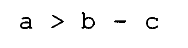
boss 9 applies a pressing force to the fixingbracket 8. - Fig. 5 shows the relation among the
hook part 16, thebosses 9, and the fixingbracket 8 simplified as a structure of a beam. In Fig. 5, the fixingbracket 8, thehook part 16, and the pressing force W applied to the fixingbracket 8 by the bosses are represented by abeam 19, asupport 18, and forces W, respectively. Since the pressing forces W are applied to both the edges of thebeam 19, there occurs warpage and both the edges of thebeam 17 are lowered in a direction of the applied forces W, thesupport 18 being a fulcrum. When describing this again in terms of the relation among thehook part 16, thebosses 9, and the fixingbracket 8, thehook part 16 being a fulcrum, thebosses 9 make the fixingbracket 8 bend in the direction opposite to the rear inside wall of the back cabinet. When the fixingbracket 8 is bent in such a manner, it comes into contact with the tips of thebosses 9, which prevents a gap from being formed. - With the above structure, the fixing
bracket 8 comes in contact with thebosses 9, preventing chatter from occurring. However, since the fixingbracket 8 is bent by the pressing forces from theboss 9, the contact area of the fixingbracket 8 and thebosses 9 is small. In this regard, the deformation of heboss 9 is made to increase by modifying the contact surface of the fixingbracket 8 and theboss 9 so as to increase the contact area. The fixingbracket 8 is made to further come into contact with theboss 9 by this, enabling the prevention of chatter. - Generally, when a stress is applied to a material, deformation occurs as well as another stress to resist this is produced. The rate of the deformed state of the material to its original state is called a "strain ε." The equation of the strain ε is shown below.

where a material length is L, and an amount of deformation is ΔL.
Moreover, the relation between a stress σ and the strain ε can be expressed by using Young's modulus E as follows.


- Fig. 6 is an enlarged view of a tip of the boss according to an embodiment of the present invention. The
boss 9 is formed such that twoannular ribs 20 whose radiuses from an axis differ are provided, protruding from the tip of theboss 9, around the first throughhole 12 of the tip of the boss. The two ribs protrude from the tip of theboss 9. The reaction force to the force applied on the fixingbracket 8 is added to theribs 20, causing the ribs to be strain-deformed. Since the contact surface of therib 20 to which the reaction force is applied is small, therib 20 deforms considerably due to the strain and becomes easily collapsed. - Fig. 7 is an enlarged view of a contact portion of the
boss 9 not havingribs 20 at its tip and the fixingbracket 8 according to an embodiment of the present invention. Fig. 8 is an enlarged view of a contact portion of theboss 9 havingribs 20 at its tip and the fixingbracket 8 according to an embodiment of the present invention. In Fig. 7, the fixingbracket 8 is warped with thehook part 16 being a fulcrum because of a pressing force from the boss and, for this reason, the tip of theboss 9 and the fixingbracket 8 are in contact at a certain point only. Therefore, a gap is produced between theboss 9 and the fixingbracket 8. In Fig. 8, although thefastening bracket 8 is similarly in contact with theribs 20, theribs 20 are deformed by a strain so that the fixingbracket 8 and theboss 9 are not in contact at one point, reducing the gap between the fixingbracket 8 and theribs 20. Accordingly, further effect of preventing chatter can be obtained. - The fixing
bracket 8 and theboss 9 reduce a gap and prevent chatter according to the structure described above. Moreover, by securing the fixingbracket 8 and theback cabinet 5 by thehook part 16 and then fastening them with screws, it becomes possible to further reduce the gap between the fixingbracket 8 and theboss 9, and to prevent the chatter. - Fig. 9 is an enlarged view of part of the back cabinet according to an embodiment of the present invention. The
back cabinet 5 is provided with afirst seat 21 which is protruding from the rear inside wall higher than theboss 9. Further, a female screw portion is made in a substantial central part of thefirst seat 21. On a substantial edge portion of the fixingbracket 8, there is provided a one-step higher second seat 22 in a step-like manner. Further, in a substantial central part of the second seat 22, there is provided a through hole for screwing opposite to the female screw portion of thefirst seat 21 of theback cabinet 5. Thefirst seat 21 and the second seat 22 are screwed so as to be in contact with each other. With the above structure, the fixingbracket 8 is further pressed by the screw to theboss 9 erected on the rear inside wall of theback cabinet 5. Thus, the fixingbracket 8 and theboss 9 further press the contact surface and reduces a gap produced in the contact portion of the fixingbracket 8 and theboss 9. After having been fixed by thehook part 16, the fixingbracket 8 and theback cabinet 5 are further fastened by screws etc. Therefore, stiffness of the fixed portion of the fixingbracket 8 and theback cabinet 5 is improved, making it possible for thesupport leg 13 fixed to the fixingbracket 8 to endure the increase in weight of themain body 6. - Thus, according to the present invention, the fixing
bracket 8 is fixed in such a way that it comes into contact with the tip of theboss 9 erected on the rear inside wall of theback cabinet 5 through the medium of thehook part 16 erected on the rear inside wall of theback cabinet 5 forming part of the main body of the liquidcrystal television set 1. With the above structure, when using the main body by supporting it with thesupport leg 13, a gap between the fixingbracket 8 and theboss 9 is reduced and the fixingbracket 8 and theboss 9 are kept in contact. Accordingly, chatter generated by interference between the fixingbracket 8 and theboss 9 caused by sound vibration etc. is prevented. - It is needless to say that the present invention is not limited to the above embodiments. The points described below should be apparent to those skilled in the art.
- · To apply mutually replaceable members and structures disclosed in the above embodiments by changing the combination thereof as required.
- · To replace, as required, the members and structures disclosed in the above embodiments with mutually replaceable members and structures not disclosed in the above embodiment but known in the art, and to apply them by changing the combination thereof · To replace, as required, the members and structures disclosed in the above embodiments with members and structures which are not disclosed in the above embodiments but can be used as substitutes for the members and structures disclosed in the above embodiments by those skilled in the art based on known arts etc. and to apply them by changing the combination thereof.
The three points described above are to be disclosed as one embodiment of the present invention.
Claims (9)
- A liquid crystal television set comprising:a liquid crystal display panel provided with a backlight including an inverter circuit and a fluorescent tube, and formed of a plurality of picture elements for displaying an image;a speaker outputting sound based on an audio signal;a circuit board receiving a television broadcast, having said liquid crystal display panel show the image, having the speaker output the sound, and including a primary side power supply circuit;a main body made up of a resin front cabinet forming a display window for said liquid crystal display panel in the front thereof and a resin back cabinet attached to the back of the front cabinet and accommodating said liquid crystal display panel, said speaker, and said circuit board;a plate-like fixing bracket attached to a rear inside wall of said back cabinet;a support leg supporting said main body from below through the medium of said fixing bracket; anda hanger member attached to the back of said cabinet, four bosses with tips contacting said fixing bracket being so erected on the rear inside wall of said back cabinet that lines connecting the four bosses form a substantial quadrangle, each boss being provided with a first through hole passing through the boss in its erected direction and also passing through the rear inside wall of said back cabinet, and said hanger member being removably fastened to said fixing bracket with screws passing through said first through holes,wherein, on the rear inside wall of said back cabinet, there is erected a hook part, protruding towards said fixed bracket, between opposing sides of the substantial quadrangle formed by the lines connecting said bosses, the tip of the hook part being bent in the shape of a hook;
wherein said fixing bracket has a second through hole through which the tip of said hook part can pass towards said boss erected corresponding to the position of said hook part; and
wherein the tip of said hook part can pass through the second through hole of said fixing bracket from the side of the rear inside wall of said back cabinet to the front side, insert a peripheral portion of said second through hole of said fixing bracket in a recess of the rear inside wall of said back cabinet to hook the peripheral portion there and, also, is positioned such that a pressing force is applied to the fixing bracket from the tip of said boss contacting said fixing bracket when said fixing bracket is hooked,
characterized in that, when each of the screws passing through said boss is unscrewed and said hanger member is removed, with respect to said fixing bracket hooked by said hook part, the pressing force is applied to the fixing bracket from the tip of said boss contacting said fixing bracket,
that, at the tip of the boss erected on the rear inside wall of said back cabinet, plastic ribs thinner than said boss are formed twofold facing said fixing bracket and
that said fixing bracket is fastened to the rear inside wall of said back cabinet with screws. - A liquid crystal display comprising:a main body having a cabinet forming a display window for the liquid crystal display panel in the front thereof;a plate-like fixing bracket attached to a rear inside wall of said cabinet;a support leg supporting said main body from below through the medium of said fixing bracket; anda hanger member attached to the back of said cabinet, a plurality of bosses with tips contacting said fixing bracket being erected on the rear inside wall of said cabinet, each boss being provided with a first through hole passing through the boss in its erected direction and also passing through the rear inside wall of said cabinet, and said hanger member being removably fastened to said fixing bracket with screws passing through said first through holes,wherein, on the rear inside wall of said cabinet, there is erected a hook part, protruding towards said fixing bracket, between said bosses, the tip of the hook part being bent in the shape of a hook;
wherein said fixing bracket has a second through hole through which the tip of said hook part can pass towards said boss erected corresponding to the position of said hook part; and
wherein the tip of said hook part can pass through the second through hole of said fixing bracket from the side of the rear inside wall of said cabinet to the front side, insert a peripheral portion of said second through hole of said fixing bracket in a recess of the rear inside wall of said cabinet to hook the peripheral portion there and, also, is positioned such that a pressing force is applied to the fixing bracket from the tip of said boss contacting said fixing bracket when said fixing bracket is hooked,
characterized in that, when each of the screws passing through said boss is unscrewed and said hanger member is removed, with respect to said fixing bracket hooked by said hook part, the pressing force is applied to the fixing bracket from the tip of said boss contacting said fixing bracket. - A liquid crystal display according to claim 2, wherein a plurality of plastic ribs thinner than said boss is formed, facing said fixing bracket, at the tip of the boss erected on the rear inside wall of said cabinet.
- A liquid crystal display according to claim 2 or claim 3, wherein said fixing bracket is fastened to the rear inside wall of said cabinet with screws.
- A liquid crystal display according to any of claims 2 to 4,
wherein there are provided on said cabinet four thin cylindrical bosses protruding from the side of the rear inside wall each having said first through hole passing through the cabinet in the axial direction of the boss; and
wherein the four bosses are arranged so that lines connecting the bosses form a substantial quadrangle. - A liquid crystal display according to claim 5, wherein, between opposing sides of the substantial quadrangle formed by said lines, there are respectively formed hook parts protruding from the rear inside wall of said cabinet, the tip of each hook part being bent in the shape of a hook.
- A liquid crystal display according to any of claims 2 to 6, wherein said fixing bracket is a plate-like metal sheet having, at both the edges, said two second rectangular through holes which said hook parts pass through.
- A liquid crystal display according to any of claims 2 to 7, wherein said boss is constructed such that two annular ribs having different radiuses from the axis are formed around the first through hole of the tip of the boss in a protruding manner from the tip of the boss.
- A liquid crystal display according to any of claims 2 to 8,
wherein said cabinet is provided with a first seat which protrudes from the rear inside wall higher than said boss;
wherein a female screw portion is provided in a substantial central part of the first seat;
wherein there is provided at the substantial edge portion a one-step higher second seat in a step-like manner;
wherein there is provided a through hole for screwing opposite to the female screw portion of the first seat of said back cabinet; and
wherein said first seat and second seat are screwed so as to be in contact with each other.
Applications Claiming Priority (1)
| Application Number | Priority Date | Filing Date | Title |
|---|---|---|---|
| JP2005008784U JP3117923U (en) | 2005-10-24 | 2005-10-24 | Liquid crystal television device, liquid crystal display device |
Publications (3)
| Publication Number | Publication Date |
|---|---|
| EP1777954A2 true EP1777954A2 (en) | 2007-04-25 |
| EP1777954A3 EP1777954A3 (en) | 2007-06-13 |
| EP1777954B1 EP1777954B1 (en) | 2008-08-06 |
Family
ID=37669603
Family Applications (1)
| Application Number | Title | Priority Date | Filing Date |
|---|---|---|---|
| EP06021983A Not-in-force EP1777954B1 (en) | 2005-10-24 | 2006-10-19 | Liquid crystal television set, liquid crystal display |
Country Status (4)
| Country | Link |
|---|---|
| US (1) | US7515222B2 (en) |
| EP (1) | EP1777954B1 (en) |
| JP (1) | JP3117923U (en) |
| DE (1) | DE602006002086D1 (en) |
Cited By (4)
| Publication number | Priority date | Publication date | Assignee | Title |
|---|---|---|---|---|
| EP1995956A1 (en) * | 2007-05-08 | 2008-11-26 | Funai Electric Co., Ltd. | Wall hanger |
| EP1995957A3 (en) * | 2007-05-22 | 2011-03-30 | Funai Electric Co., Ltd. | Television receiver housing |
| EP2393289A4 (en) * | 2009-01-29 | 2012-08-22 | Panasonic Corp | DISPLAY UNIT |
| CN105402215A (en) * | 2015-12-22 | 2016-03-16 | 合肥惠科金扬科技有限公司 | Electric appliance connecting structure and television or display thereof |
Families Citing this family (14)
| Publication number | Priority date | Publication date | Assignee | Title |
|---|---|---|---|---|
| JP4893302B2 (en) * | 2006-12-28 | 2012-03-07 | 船井電機株式会社 | Panel type television and display panel mounting structure |
| CN101295088B (en) * | 2007-04-25 | 2011-06-15 | 群康科技(深圳)有限公司 | Liquid crystal display device |
| JP5380300B2 (en) * | 2007-11-15 | 2014-01-08 | パナソニック株式会社 | Display device |
| JP2009159084A (en) * | 2007-12-25 | 2009-07-16 | Orion Denki Kk | Display device |
| EP2214462B1 (en) * | 2009-01-30 | 2012-09-19 | SANYO Electric Co., Ltd. | Display apparatus and display system |
| CN201489238U (en) * | 2009-08-27 | 2010-05-26 | 深圳帝光电子有限公司 | Double-layered panel ultra-thin LCD device |
| TWI403786B (en) * | 2009-09-25 | 2013-08-01 | Innolux Corp | Liquid crystal display and assembly method of the same |
| JP4792119B1 (en) * | 2010-06-17 | 2011-10-12 | 株式会社東芝 | TV and electronics |
| JP2012189914A (en) * | 2011-03-14 | 2012-10-04 | Funai Electric Co Ltd | Liquid crystal display device |
| KR20130027304A (en) * | 2011-09-07 | 2013-03-15 | 삼성전자주식회사 | Control panel assembly and laundry treating apparatus having the same |
| JP5232279B2 (en) * | 2011-09-15 | 2013-07-10 | 株式会社東芝 | Electronics |
| US9119295B2 (en) * | 2011-10-11 | 2015-08-25 | Rockwell Automation Technologies, Inc. | Display mounting techniques |
| TWI489704B (en) * | 2012-03-30 | 2015-06-21 | 緯創資通股份有限公司 | Electronic device and its locking device |
| KR102504803B1 (en) | 2016-04-06 | 2023-02-28 | 엘지전자 주식회사 | Display device |
Family Cites Families (21)
| Publication number | Priority date | Publication date | Assignee | Title |
|---|---|---|---|---|
| JPH0748910B2 (en) | 1988-12-28 | 1995-05-24 | 松下電器産業株式会社 | Speaker mounting device |
| JPH03102924U (en) | 1990-02-06 | 1991-10-25 | ||
| US5455743A (en) * | 1993-02-19 | 1995-10-03 | Sony Corporation | Switch panel for electronic device |
| US5410373A (en) * | 1993-09-02 | 1995-04-25 | Berkeley Process Control | Chassis assembly with means for mounting within thin wall opening |
| JPH08126087A (en) | 1994-10-20 | 1996-05-17 | Matsushita Electric Ind Co Ltd | Horn speaker holding device |
| JPH10164464A (en) | 1996-11-26 | 1998-06-19 | Funai Electric Co Ltd | Loudspeaker installation device for television receiver |
| JPH11331734A (en) | 1998-04-30 | 1999-11-30 | Daewoo Electronics Co Ltd | Vibration reducing device fur television set |
| KR20000060243A (en) | 1999-03-12 | 2000-10-16 | 구자홍 | speaker installing unit for display device |
| KR100526620B1 (en) | 1999-05-01 | 2005-11-08 | 삼성전자주식회사 | Structure For Fixing VESA Cover To L.C.D Monitor |
| JP3619746B2 (en) | 2000-04-19 | 2005-02-16 | 三洋電機株式会社 | TV speaker mounting structure |
| JP2001359022A (en) | 2000-06-12 | 2001-12-26 | Sony Corp | Electronic device |
| KR100796484B1 (en) | 2001-05-30 | 2008-01-21 | 엘지.필립스 엘시디 주식회사 | Display housing mounting structure for monitor |
| JP2003008252A (en) | 2001-06-25 | 2003-01-10 | Mitsubishi Electric Corp | Flat panel display device |
| JP2003015542A (en) | 2001-06-27 | 2003-01-17 | Toshiba Corp | Display device and liquid crystal display device |
| US7604206B2 (en) | 2001-11-19 | 2009-10-20 | Samsung Electronics Co., Ltd. | Monitor improved in a tilting and combining structure |
| JP4214751B2 (en) | 2002-10-07 | 2009-01-28 | パナソニック株式会社 | Display device |
| US6672560B1 (en) * | 2003-03-06 | 2004-01-06 | James K. Hart | Vibration-isolating mounting bracket assembly for television supporting frame |
| JP4224706B2 (en) * | 2004-04-16 | 2009-02-18 | 船井電機株式会社 | Plasma television, panel display type television, and panel display type television assembly method |
| JP3599332B1 (en) | 2004-07-16 | 2004-12-08 | オリオン電機株式会社 | Display device |
| JP4210860B2 (en) * | 2005-12-26 | 2009-01-21 | 船井電機株式会社 | Panel television and LCD television |
| TW200735657A (en) * | 2006-03-06 | 2007-09-16 | Digimedia Technology Co Ltd | Liquid crystal television |
-
2005
- 2005-10-24 JP JP2005008784U patent/JP3117923U/en not_active Expired - Fee Related
-
2006
- 2006-10-18 US US11/583,220 patent/US7515222B2/en not_active Expired - Fee Related
- 2006-10-19 EP EP06021983A patent/EP1777954B1/en not_active Not-in-force
- 2006-10-19 DE DE602006002086T patent/DE602006002086D1/en active Active
Cited By (6)
| Publication number | Priority date | Publication date | Assignee | Title |
|---|---|---|---|---|
| EP1995956A1 (en) * | 2007-05-08 | 2008-11-26 | Funai Electric Co., Ltd. | Wall hanger |
| US7988121B2 (en) | 2007-05-08 | 2011-08-02 | Funai Electric Co., Ltd. | Wall hanger |
| EP1995957A3 (en) * | 2007-05-22 | 2011-03-30 | Funai Electric Co., Ltd. | Television receiver housing |
| US8154668B2 (en) | 2007-05-22 | 2012-04-10 | Funai Electric Co., Ltd. | Television receiver |
| EP2393289A4 (en) * | 2009-01-29 | 2012-08-22 | Panasonic Corp | DISPLAY UNIT |
| CN105402215A (en) * | 2015-12-22 | 2016-03-16 | 合肥惠科金扬科技有限公司 | Electric appliance connecting structure and television or display thereof |
Also Published As
| Publication number | Publication date |
|---|---|
| US20070091226A1 (en) | 2007-04-26 |
| EP1777954B1 (en) | 2008-08-06 |
| DE602006002086D1 (en) | 2008-09-18 |
| JP3117923U (en) | 2006-01-19 |
| US7515222B2 (en) | 2009-04-07 |
| EP1777954A3 (en) | 2007-06-13 |
Similar Documents
| Publication | Publication Date | Title |
|---|---|---|
| EP1777954B1 (en) | Liquid crystal television set, liquid crystal display | |
| JP5100880B1 (en) | Display device and television receiver | |
| US7667782B2 (en) | Liquid crystal display device capable of restraining deformation of a cabinet by heat | |
| US8594360B2 (en) | Mounting structure for speaker and flat panel display | |
| EP2565743A2 (en) | Display device and television device | |
| US7477328B2 (en) | Plasma television, display panel type television, and fabrication method for display panel type television | |
| KR100840714B1 (en) | Liquid crystal display | |
| JP2022162164A (en) | Method for manufacturing keyboard instrument and keyboard instrument | |
| KR100630973B1 (en) | Display device | |
| JP2015025866A (en) | Display device | |
| JP2012053082A (en) | Image display device | |
| JP3115175U (en) | Liquid crystal television and display device housing structure | |
| EP2166428B1 (en) | Stand attachment structure | |
| JP4019381B2 (en) | Liquid crystal television and liquid crystal display device | |
| CN216119304U (en) | Display device | |
| KR20040009338A (en) | Monitor | |
| CN222618929U (en) | Display device | |
| CN222085533U (en) | Display device | |
| CN222085527U (en) | Display device | |
| CN223105672U (en) | Display device | |
| KR100769165B1 (en) | Combined Structure of Flat Panel Display and System | |
| CN211580441U (en) | Mounting bracket for fixing panel display and guide rail type instrument | |
| KR100589779B1 (en) | LCD Panel Brackets | |
| CN209313945U (en) | A kind of Straight-down type liquid crystal television structure and Straight-down type liquid crystal television | |
| KR19990070452A (en) | Assembly structure of LCD |
Legal Events
| Date | Code | Title | Description |
|---|---|---|---|
| PUAI | Public reference made under article 153(3) epc to a published international application that has entered the european phase |
Free format text: ORIGINAL CODE: 0009012 |
|
| AK | Designated contracting states |
Kind code of ref document: A2 Designated state(s): AT BE BG CH CY CZ DE DK EE ES FI FR GB GR HU IE IS IT LI LT LU LV MC NL PL PT RO SE SI SK TR |
|
| AX | Request for extension of the european patent |
Extension state: AL BA HR MK YU |
|
| PUAL | Search report despatched |
Free format text: ORIGINAL CODE: 0009013 |
|
| AK | Designated contracting states |
Kind code of ref document: A3 Designated state(s): AT BE BG CH CY CZ DE DK EE ES FI FR GB GR HU IE IS IT LI LT LU LV MC NL PL PT RO SE SI SK TR |
|
| AX | Request for extension of the european patent |
Extension state: AL BA HR MK YU |
|
| RIC1 | Information provided on ipc code assigned before grant |
Ipc: H04N 5/64 20060101AFI20070130BHEP Ipc: G06F 1/16 20060101ALI20070510BHEP |
|
| 17P | Request for examination filed |
Effective date: 20070724 |
|
| 17Q | First examination report despatched |
Effective date: 20070827 |
|
| AKX | Designation fees paid |
Designated state(s): DE FR GB |
|
| GRAP | Despatch of communication of intention to grant a patent |
Free format text: ORIGINAL CODE: EPIDOSNIGR1 |
|
| GRAS | Grant fee paid |
Free format text: ORIGINAL CODE: EPIDOSNIGR3 |
|
| GRAA | (expected) grant |
Free format text: ORIGINAL CODE: 0009210 |
|
| AK | Designated contracting states |
Kind code of ref document: B1 Designated state(s): DE FR GB |
|
| REG | Reference to a national code |
Ref country code: GB Ref legal event code: FG4D |
|
| REF | Corresponds to: |
Ref document number: 602006002086 Country of ref document: DE Date of ref document: 20080918 Kind code of ref document: P |
|
| PLBE | No opposition filed within time limit |
Free format text: ORIGINAL CODE: 0009261 |
|
| STAA | Information on the status of an ep patent application or granted ep patent |
Free format text: STATUS: NO OPPOSITION FILED WITHIN TIME LIMIT |
|
| 26N | No opposition filed |
Effective date: 20090507 |
|
| REG | Reference to a national code |
Ref country code: FR Ref legal event code: PLFP Year of fee payment: 10 |
|
| PGFP | Annual fee paid to national office [announced via postgrant information from national office to epo] |
Ref country code: FR Payment date: 20150908 Year of fee payment: 10 |
|
| PGFP | Annual fee paid to national office [announced via postgrant information from national office to epo] |
Ref country code: DE Payment date: 20151013 Year of fee payment: 10 Ref country code: GB Payment date: 20151014 Year of fee payment: 10 |
|
| REG | Reference to a national code |
Ref country code: DE Ref legal event code: R119 Ref document number: 602006002086 Country of ref document: DE |
|
| GBPC | Gb: european patent ceased through non-payment of renewal fee |
Effective date: 20161019 |
|
| REG | Reference to a national code |
Ref country code: FR Ref legal event code: ST Effective date: 20170630 |
|
| PG25 | Lapsed in a contracting state [announced via postgrant information from national office to epo] |
Ref country code: FR Free format text: LAPSE BECAUSE OF NON-PAYMENT OF DUE FEES Effective date: 20161102 Ref country code: DE Free format text: LAPSE BECAUSE OF NON-PAYMENT OF DUE FEES Effective date: 20170503 Ref country code: GB Free format text: LAPSE BECAUSE OF NON-PAYMENT OF DUE FEES Effective date: 20161019 |