EP1777992B1 - Elément flexible plat, en particulier pour chauffages de sièges, et le procédé de fabrication d'un élément chauffable flexible - Google Patents
Elément flexible plat, en particulier pour chauffages de sièges, et le procédé de fabrication d'un élément chauffable flexible Download PDFInfo
- Publication number
- EP1777992B1 EP1777992B1 EP06017871.2A EP06017871A EP1777992B1 EP 1777992 B1 EP1777992 B1 EP 1777992B1 EP 06017871 A EP06017871 A EP 06017871A EP 1777992 B1 EP1777992 B1 EP 1777992B1
- Authority
- EP
- European Patent Office
- Prior art keywords
- conductors
- filaments
- heating element
- surface heating
- flexible surface
- Prior art date
- Legal status (The legal status is an assumption and is not a legal conclusion. Google has not performed a legal analysis and makes no representation as to the accuracy of the status listed.)
- Active
Links
Images

Classifications
-
- H—ELECTRICITY
- H05—ELECTRIC TECHNIQUES NOT OTHERWISE PROVIDED FOR
- H05B—ELECTRIC HEATING; ELECTRIC LIGHT SOURCES NOT OTHERWISE PROVIDED FOR; CIRCUIT ARRANGEMENTS FOR ELECTRIC LIGHT SOURCES, IN GENERAL
- H05B3/00—Ohmic-resistance heating
- H05B3/20—Heating elements having extended surface area substantially in a two-dimensional [2D] plane, e.g. plate-heater
- H05B3/34—Heating elements having extended surface area substantially in a two-dimensional [2D] plane, e.g. plate-heater flexible, e.g. heating nets or webs
-
- B—PERFORMING OPERATIONS; TRANSPORTING
- B60—VEHICLES IN GENERAL
- B60N—SEATS SPECIALLY ADAPTED FOR VEHICLES; VEHICLE PASSENGER ACCOMMODATION NOT OTHERWISE PROVIDED FOR
- B60N2/00—Seats specially adapted for vehicles; Arrangement or mounting of seats in vehicles
- B60N2/56—Heating or ventilating devices
- B60N2/5678—Heating or ventilating devices characterised by electrical systems
- B60N2/5685—Resistance
-
- H—ELECTRICITY
- H05—ELECTRIC TECHNIQUES NOT OTHERWISE PROVIDED FOR
- H05B—ELECTRIC HEATING; ELECTRIC LIGHT SOURCES NOT OTHERWISE PROVIDED FOR; CIRCUIT ARRANGEMENTS FOR ELECTRIC LIGHT SOURCES, IN GENERAL
- H05B3/00—Ohmic-resistance heating
- H05B3/20—Heating elements having extended surface area substantially in a two-dimensional [2D] plane, e.g. plate-heater
- H05B3/34—Heating elements having extended surface area substantially in a two-dimensional [2D] plane, e.g. plate-heater flexible, e.g. heating nets or webs
- H05B3/342—Heating elements having extended surface area substantially in a two-dimensional [2D] plane, e.g. plate-heater flexible, e.g. heating nets or webs heaters used in textiles
-
- H—ELECTRICITY
- H05—ELECTRIC TECHNIQUES NOT OTHERWISE PROVIDED FOR
- H05B—ELECTRIC HEATING; ELECTRIC LIGHT SOURCES NOT OTHERWISE PROVIDED FOR; CIRCUIT ARRANGEMENTS FOR ELECTRIC LIGHT SOURCES, IN GENERAL
- H05B2203/00—Aspects relating to Ohmic resistive heating covered by group H05B3/00
- H05B2203/002—Heaters using a particular layout for the resistive material or resistive elements
- H05B2203/005—Heaters using a particular layout for the resistive material or resistive elements using multiple resistive elements or resistive zones isolated from each other
-
- H—ELECTRICITY
- H05—ELECTRIC TECHNIQUES NOT OTHERWISE PROVIDED FOR
- H05B—ELECTRIC HEATING; ELECTRIC LIGHT SOURCES NOT OTHERWISE PROVIDED FOR; CIRCUIT ARRANGEMENTS FOR ELECTRIC LIGHT SOURCES, IN GENERAL
- H05B2203/00—Aspects relating to Ohmic resistive heating covered by group H05B3/00
- H05B2203/011—Heaters using laterally extending conductive material as connecting means
-
- H—ELECTRICITY
- H05—ELECTRIC TECHNIQUES NOT OTHERWISE PROVIDED FOR
- H05B—ELECTRIC HEATING; ELECTRIC LIGHT SOURCES NOT OTHERWISE PROVIDED FOR; CIRCUIT ARRANGEMENTS FOR ELECTRIC LIGHT SOURCES, IN GENERAL
- H05B2203/00—Aspects relating to Ohmic resistive heating covered by group H05B3/00
- H05B2203/014—Heaters using resistive wires or cables not provided for in H05B3/54
-
- H—ELECTRICITY
- H05—ELECTRIC TECHNIQUES NOT OTHERWISE PROVIDED FOR
- H05B—ELECTRIC HEATING; ELECTRIC LIGHT SOURCES NOT OTHERWISE PROVIDED FOR; CIRCUIT ARRANGEMENTS FOR ELECTRIC LIGHT SOURCES, IN GENERAL
- H05B2203/00—Aspects relating to Ohmic resistive heating covered by group H05B3/00
- H05B2203/017—Manufacturing methods or apparatus for heaters
-
- H—ELECTRICITY
- H05—ELECTRIC TECHNIQUES NOT OTHERWISE PROVIDED FOR
- H05B—ELECTRIC HEATING; ELECTRIC LIGHT SOURCES NOT OTHERWISE PROVIDED FOR; CIRCUIT ARRANGEMENTS FOR ELECTRIC LIGHT SOURCES, IN GENERAL
- H05B2203/00—Aspects relating to Ohmic resistive heating covered by group H05B3/00
- H05B2203/029—Heaters specially adapted for seat warmers
Definitions
- the present invention relates to a flexible surface heating element, in particular for seat heaters according to the preamble of claim 1.
- the present invention relates to a method for producing a flexible surface heating element according to the preamble of claim 17.
- a particular embodiment of such a surface heating element consists of two opposing contact strips, which generally consist of metallic Leitem and have the task of providing the heating conductors, which extend from contact strip to contact strip, electrically supplied with electricity. This happens because the heating conductors cut the contact conductors and are mechanically pressed against them, so that an electrical contact is formed. This results in a parallel connection of the heating element, wherein by selecting the electrical conductivities of the heating element, the heating power can be adjusted.
- Such Flamban carving shame are from the DE 4142774 A1 as well as the DE 4020580 A1
- the heating elements are laid as weft threads sinusoidally over the stitch threads of a knitted base material and integrated at least at the maxima of the amplitudes in the meshes of the textile base material.
- Power supply conductors are arranged as contact strips on opposite repeat edges perpendicular to the sine axis and each heat conductor is electrically connected to each contact conductor
- the heating conductors may consist of steel wire or carbon fiber.
- the contact conductors are made of carbon fiber material. In one embodiment, a carbon fiber filament may be used as the heating conductor.
- DE 4020580 A1 is an electric surface heating element of net-like knitted fabric constructed with Heizieltern and connected to the ends of the heating conductors Kunststoffleitem.
- the heating conductors are essentially parallel to one another and are firmly bound at intervals in the mesh composite of the textile knitwear in such a way that they loop, wave or meander; the contact conductors are substantially perpendicular to the Edelleitem.
- a surface heating element which consists of substantially parallel heating wires, which are electrically connected at their ends and / or deflection with power supply conductors, each power supply conductor is designed as a flexible contact strip with a plurality of individual conductors, which are electrically connected in parallel with the heating wires, and wherein the surface heating element is integrated in an elastic carrier material exists.
- This document also describes conductive strips between which the heating wire is placed. These conductive tapes can be made of steel or copper, or mixtures of both materials.
- the contact conductors which are provided at the edges of the heating field, are designed as contact strips in various embodiments.
- the contact strips may in one embodiment consist of a carrier tape on which the contact conductors are mounted.
- a braided Metallgewirke is specified for the contact conductor. According to this document, only one type of conductor is provided for the contact conductors, namely those made of copper or those in the form of a metal knit.
- the present invention is now based on the object to provide a contact strip that reduces the risk of breakage despite high mechanical load and high electrical currents so far that equipped with surface heating both between reference and Wegkem and in relation can be used without the risk of Overheating or even a fire arises.
- the function of the contact strip is also completely given when the conductor of higher conductivity at one or more place (s) is interrupted. At these points of interruption, only the steel conductors contribute to the power line. Due to the very short area, which is limited in each case by the ends of the conductors of higher conductivity, the ent-standing power loss at the point of interruption is so low that a fire or a noticeable overheating of the surface can be excluded.
- the area in which only the steel conductors receive the current can be kept particularly short by the contact strip (s) consisting of at least one strand and preferably several strands of steel conductors and at least one strand on the opposite side of the steel conductors and preferably several undulating strands of conductors of higher conductivity than the steel conductors is or are arranged, so that the power loss is particularly low and the overheating reaches only a level which leads neither to the fire nor to noticeable overheating of the seat surface.
- the number of steel filaments combined into a bundle forming a respective conductor can be between 20 to 2000 individual filaments; Preferably, the number should be 150 to 500 individual filaments.
- the thickness of the individual steel filaments, which are combined into a bundle, is 8 to 15 ⁇ m.
- the thickness of the individual filaments of higher conductivity should be between 50 ⁇ m and 100 ⁇ m.
- These different thicknesses, on the one hand the individual steel filaments, on the other hand the filaments of higher conductivity, are due to the fact that steel filaments can be made very thin without the fibers breaking.
- the cross sections of the individual steel filaments are selected at least three times smaller than the cross sections of the filaments of the conductors with higher conductivity.
- the cross sections of the individual steel filaments should be at least 10 to 30 times smaller than the cross sections of the filaments of the higher conductivity conductors.
- the higher conductivity conductors are wavy or meandering, crossing and contacting the respective steel conductors; This ensures that the two types of conductors are electrically connected to each other and in case of breakage of the conductor of higher conductivity, the defect remains locally limited and the broken conductor ends do not migrate away from each other.
- the steel filaments should be formed by stainless steel filaments.
- the filaments of the higher conductivity conductors are formed of copper or copper alloys due to the conductance of this material.
- the filaments of the conductors with higher conductivity may additionally have a corrosion protection layer, which is preferably formed from tin, silver or nickel.
- the two conductors of the contact strip are preferably incorporated into the textile tape by means of active technique.
- Polyester threads or polyamide threads should be used to fasten the conductors to the textile band, since the textile fibers can be kept very thin and only slightly hinder the heating conductors when they rest on the contact conductors.
- Particularly preferred is a procedure in which the conductors are applied by means of stitching on the tape;
- a ladder type is introduced in the short or partial shot, and only the / the polyester thread / polyester threads or the / the Polyamidfaden / polyamide threads forms / form the stitches.
- This procedure ensures that the types of conductors are prefixed to one another and can no longer move relative to one another in further method steps.
- At least the conductors of large cross section of the contact strip should be arranged wave-like or meandering over the carrier tape, wherein the shaft axis in this case corresponds to the tape direction.
- surface heating elements are used as surface heating elements for seat heaters of vehicles, where the above-mentioned advantages are particularly significant.
- a flexible surface heating element 1 is shown, as it can be sewn, for example, in the seat of a vehicle as a seat heater.
- This surface heating element 1 comprises a textile carrier material 2, on which in predetermined patterns heating element 3, a Heating field 4 forming, are incorporated by means of active technology.
- the heating conductors 3 can run closer or further apart or the number of heating conductors per unit area can be increased or decreased, as exemplified in FIG. 3 in the upper region and in the lower region of the heating field 4 is shown.
- a respective contact strip 6 is placed, via which the heating field is supplied with power.
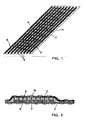
- Such a contact strip 6 is in their details in the Figures 1 and 2 shown.
- such a contact strip 6 as a carrier on a textile tape 7, which consists for example of polyester or polyamide, prepared in active technology.
- a textile tape 7 which consists for example of polyester or polyamide, prepared in active technology.
- a plurality of conductors 8 which are each composed of bundles of steel filaments. These steel filaments may have a diameter in the range of 8 to 30 ⁇ m; The number of individual filaments can be between 150 to 500.
- a second type of conductor which runs in waves or meanders, so that these conductors of the second type of conductor intersect the steel filament conductors.
- These second conductor type conductors 9 are formed of a higher conductivity material compared with the steel filament conductors 8, each of bundles of a plurality of single filaments.
- This second type of conductor may be conductor 9 made of copper or copper alloys, ie a material which has a higher conductivity than the steel filaments.
- the conductors 8, 9 of this contact strip 6 are fastened on the textile belt 7 by means of active technology, which is in FIG. 1 not shown in this detail.
- FIG. 2 is the contact strip 6, as in FIG. 1 is shown arranged in a sectional view on the heating field 4.
- the wavy or meandering conductors of higher conductivity below the steel conductors 8, ie the contact strip, as in FIG. 2 is used opposite the representation of the FIG. 1 turned.
- the contact strip 6 is acted upon by the textile belt 7 and the heating field 4 with its textile substrate 2 and the heating conductors 3 to form a composite via a textile, stitch-forming thread 10 by means of stitching or knitting technique.
- the contact strips 6 are first prepared in the form of textile strips 7 with the two types of conductors 8 and 9, then this contact strip 6 is glued to the underside of the textile tape 7 on the textile substrate 2 for the heating field 4 and thus fixed, then the heating element 3 of the heating field 4, which are preferably formed of carbon fibers, applied by being placed in the predetermined patterns on the substrate 2 and sewn thereto, and at the same time the contact strip 6, which is first fixed to the substrate only was incorporated by means of active technology in the textile substrate 2.
- this surface heating element is very flexible and compliant, not only in the area of the heating field 4, but also in the area of the contact strips 6.
- the two different types of conductors i. on the one hand the steel conductor 8 and on the other hand the conductor 9 of higher conductivity than the steel conductors, in the present example of conductors made of copper or copper wires, ensures that a highly conductive, and suitable for high bending cycle cycles contact band is formed.
- the conductors 8 and 9 from a large number of very thin single filaments, it is achieved that the tape is soft and shows little sign on the reference surface.
Landscapes
- Engineering & Computer Science (AREA)
- Textile Engineering (AREA)
- Aviation & Aerospace Engineering (AREA)
- Transportation (AREA)
- Mechanical Engineering (AREA)
- Surface Heating Bodies (AREA)
Claims (22)
- Elément chauffant mince de surface (1), flexible, notamment pour des systèmes de chauffage de sièges, comprenant un matériau de support flexible (2) dans la zone duquel est agencé un champ chauffant (4) en conducteurs chauffants (3), qui sont reliés à au moins un ruban de contact (6) par une liaison électriquement conductrice, élément chauffant dans lequel dans la zone du dit au moins un ruban de contact (6) existent au moins deux types de conducteurs en matériau différent, et dans lequel les deux types de conducteurs sont reliés mutuellement sur le plan électrique, caractérisé en ce que le ruban de contact (6) est réalisé sous la forme d'une bande textile, qui renferme une part de conducteurs (8) sous la forme de filaments d'acier et une part de conducteurs (9) sous la forme de filaments d'une conductivité plus élevée que celle des filaments d'acier, les conducteurs (9) de conductivité plus élevée s'étendant de manière ondulée ou en forme de méandres, en croisant les conducteurs d'acier (8) considérés et en étant en contact avec ceux-ci, et les conducteurs (9) de conductivité plus élevée se situant uniquement au-dessus ou uniquement en-dessous des filaments d'acier (8), et en ce que les conducteurs (8, 9) sont maintenus sur la bande textile (7) au moyen de fils textiles et/ou métalliques, la bande textile (7) étant reliée au matériau de support (2).
- Elément chauffant mince de surface, flexible, selon la revendication 1, caractérisé en ce qu'un grand nombre de filaments d'acier rassemblés en un faisceau forment au moins des conducteurs (8) individuels.
- Elément chauffant mince de surface, flexible, selon la revendication 1 ou la revendication 2, caractérisé en ce qu'au moins des conducteurs individuels (9) de conductivité plus élevée sont formés d'un grand nombre de filaments rassemblés en un faisceau.
- Elément chauffant mince de surface, flexible, selon la revendication 2, caractérisé en ce que le faisceau des filaments d'acier du conducteur (8) considéré est constitué de 20 à 2000 filaments individuels.
- Elément chauffant mince de surface, flexible, selon la revendication 4, caractérisé en ce que le faisceau des filaments d'acier du conducteur (8) considéré est constitué de 150 à 500 filaments individuels.
- Elément chauffant mince de surface, flexible, selon la revendication 3, caractérisé en ce que les filaments du conducteur (9) considéré, de conductivité plus élevée, sont constitués de 20 à 500 filaments individuels.
- Elément chauffant mince de surface, flexible, selon l'une des revendications 1 à 6, caractérisé en ce que l'épaisseur des filaments d'acier individuels vaut de 8 à 15 µm.
- Elément chauffant mince de surface, flexible, selon l'une des revendications 1 à 7, caractérisé en ce que l'épaisseur des filaments individuels de conductivité plus élevée vaut environ 50 µm.
- Elément chauffant mince de surface, flexible, selon l'une des revendications 1 à 8, caractérisé en ce que les sections transversales des filaments d'acier individuels (8) sont au moins trois fois plus petites que les sections transversales des filaments des conducteurs (9) de conductivité plus élevée.
- Elément chauffant mince de surface, flexible, selon la revendication 9, caractérisé en ce que les sections transversales des filaments d'acier individuels (8) sont au moins 10 à 30 fois plus petites que les sections transversales des filaments des conducteurs (9) de conductivité plus élevée.
- Elément chauffant mince de surface, flexible, selon l'une des revendications 1 à 10, caractérisé en ce que les conducteurs (8), constitués par les filaments d'acier, s'étendent sensiblement de manière rectiligne.
- Elément chauffant mince de surface, flexible, selon l'une des revendications 1 à 11, caractérisé en ce que seuls les conducteurs d'acier (8) ou seuls les conducteurs (9) de conductivité plus élevée sont reliés électriquement aux fibres conductrices (3) du champ chauffant (4).
- Elément chauffant mince de surface, flexible, selon l'une des revendications 1 à 12, caractérisé en ce que les filaments d'acier (8) sont constitués de filaments d'acier fin spécial.
- Elément chauffant mince de surface, flexible, selon l'une des revendications 1 à 13, caractérisé en ce que les filaments des conducteurs (9) de conductibilité plus élevée sont réalisés en cuivre ou en alliages de cuivre.
- Elément chauffant mince de surface, flexible, selon l'une des revendications 1 à 14, caractérisé en ce que les filaments des conducteurs (9) de conductibilité plus élevée présentent en supplément une couche de protection contre la corrosion.
- Elément chauffant mince de surface, flexible, selon la revendication 15, caractérisé en ce que la couche de protection est réalisée en étain, argent ou nickel.
- Procédé de fabrication d'un élément chauffant mince de surface (1), flexible, notamment d'un élément chauffant mince de surface, flexible, pour des systèmes de chauffage de sièges, comprenant un champ chauffant (4) en conducteurs chauffants (3), en particulier des fibres de carbone, que l'on agence dans la région d'un matériau de support flexible (2), et que l'on relie électriquement à au moins un ruban de contact (6), élément chauffant dans lequel dans la zone du dit ruban de contact (6) existent au moins deux types de conducteurs en matériau différent, que l'on relie mutuellement sur le plan électrique, caractérisé en ce que le ruban de contact (6) est réalisé sous la forme d'une bande textile, qui renferme une part de conducteurs (8) sous la forme de filaments d'acier et une part de conducteurs (9) sous la forme de filaments d'une conductivité plus élevée que celle des filaments d'acier, les conducteurs (9) de conductivité plus élevé étant agencés de manière ondulée ou en forme de méandres, en croisant les conducteurs d'acier (8) considérés et en étant en contact avec ceux-ci, et les conducteurs (9) de conductivité plus élevée se situant uniquement au-dessus ou uniquement en-dessous des filaments d'acier (8), et en ce que les conducteurs (8, 9) sont maintenus sur la bande textile (7) au moyen de fils textiles et/ou métalliques, et la bande textile (7) étant reliée au matériau de support (2).
- Procédé selon la revendication 17, caractérisé en ce que les deux conducteurs (8, 9) du ruban de contact (6) sont inclus dans la bande textile (10) par une technique de tricot.
- Procédé selon la revendication 17, caractérisé en ce que l'on met en oeuvre des fils de polyester ou des fils de polyamide en guise de fils pour fixer les conducteurs (8, 9) à la bande textile (10).
- Procédé selon la revendication 17, caractérisé en ce qu'on rapporte les conducteurs (8, 9) sur la bande (10) moyennant une technique de couture-tricotage (du type Malimo), au moins un type de conducteur étant inséré en duite courte ou partielle, et en ce qu'exclusivement le/les fil(s) de polyester ou le/les fil(s) de polyamide forme/forment des mailles.
- Procédé selon la revendication 17, caractérisé en ce que l'on agence au moins un conducteur (9) du ruban de contact (6) selon une forme ondulée ou en méandres le long de la bande de support (7), l'axe d'ondulation correspondant à la direction de la bande.
- Utilisation d'un élément chauffant mince de surface selon l'une des revendications 1 à 16 en tant qu'élément chauffant mince de surface (1) pour un système de chauffage de siège d'un siège de véhicule.
Applications Claiming Priority (1)
| Application Number | Priority Date | Filing Date | Title |
|---|---|---|---|
| DE102005050459A DE102005050459B3 (de) | 2005-10-19 | 2005-10-19 | Flexibles Flächenheizelement, insbesondere für Sitzheizungen, und Verfahren zur Herstellung eines flexiblen Heizelements |
Publications (3)
| Publication Number | Publication Date |
|---|---|
| EP1777992A2 EP1777992A2 (fr) | 2007-04-25 |
| EP1777992A3 EP1777992A3 (fr) | 2008-03-05 |
| EP1777992B1 true EP1777992B1 (fr) | 2013-05-29 |
Family
ID=37547498
Family Applications (1)
| Application Number | Title | Priority Date | Filing Date |
|---|---|---|---|
| EP06017871.2A Active EP1777992B1 (fr) | 2005-10-19 | 2006-08-28 | Elément flexible plat, en particulier pour chauffages de sièges, et le procédé de fabrication d'un élément chauffable flexible |
Country Status (3)
| Country | Link |
|---|---|
| US (1) | US7705271B2 (fr) |
| EP (1) | EP1777992B1 (fr) |
| DE (1) | DE102005050459B3 (fr) |
Families Citing this family (37)
| Publication number | Priority date | Publication date | Assignee | Title |
|---|---|---|---|---|
| DE102006021649C5 (de) * | 2006-05-08 | 2013-10-02 | W.E.T. Automotive Systems Ag | Flächiges Heizelement |
| DE102007051421A1 (de) | 2007-10-25 | 2009-05-07 | I.G. Bauerhin Gmbh | Heizelement für Fahrzeugsitze oder Lenkräder sowie Verfahren zum Herstellen des Heizelements |
| DE102007056465B4 (de) * | 2007-11-22 | 2010-06-02 | I.G. Bauerhin Gmbh | Kraftfahrzeugsitz mit Sitzheizung |
| TW200925344A (en) * | 2007-12-12 | 2009-06-16 | Everest Textile Co Ltd | Electric heating fabric device |
| DE102008035057B4 (de) | 2008-07-26 | 2023-01-26 | Volkswagen Ag | Textiles Flächenheizelement |
| DE102008039840A1 (de) | 2008-08-27 | 2010-03-04 | Sgl Carbon Ag | Streckgerissene Carbonfasergarne für eine Heizvorrichtung |
| CN103097184B (zh) * | 2011-03-07 | 2016-01-20 | 松下知识产权经营株式会社 | 车辆用座椅加热器 |
| WO2012136418A1 (fr) * | 2011-04-04 | 2012-10-11 | Nv Bekaert Sa | Câble chauffant comprenant des monofilaments d'acier |
| JP5436491B2 (ja) * | 2011-05-20 | 2014-03-05 | 北陸エステアール協同組合 | 面状発熱体 |
| DE112012004179T5 (de) * | 2011-10-06 | 2014-09-11 | Iee International Electronics & Engineering S.A. | Elektrisch leitfähige Textilien für Insassenerfassungs-und/oder Heizanwendungen |
| TWI467070B (zh) * | 2011-12-16 | 2015-01-01 | Kings Metal Fiber Technologies | 縫織電性連接結構 |
| KR101504802B1 (ko) | 2012-01-31 | 2015-03-30 | 실버레이 주식회사 | 도전선 손상방지기능을 갖춘 면상 도전체 |
| DE102013203584B4 (de) * | 2013-03-01 | 2016-01-07 | Beiersdorf Ag | Heizelement mit flächiger, Wärme entwickelnder Schicht, Pflaster mit Heizelement und Verfahren zur Herstellung eines Heizelements |
| DE102013226911A1 (de) | 2013-12-20 | 2015-06-25 | Benecke-Kaliko Ag | Elektrisch heizbares Flächenelement |
| FI10797U1 (fi) * | 2014-12-04 | 2015-03-10 | Wicetec Oy | Johdinliitos kuparijohtimen kytkemiseksi |
| EP3344492B1 (fr) * | 2015-09-04 | 2020-03-04 | Magna Seating Inc. | Siège de véhicule à conductivité thermique améliorée |
| CN113002105B (zh) * | 2015-11-20 | 2023-06-06 | 琳得科株式会社 | 片材、发热体、及发热装置 |
| US10442328B2 (en) | 2016-06-21 | 2019-10-15 | Kongsberg Automotive Ab | Assembly, system, and circuit with combined heating and occupancy detecting for a vehicle seat |
| CN108859887A (zh) * | 2017-05-08 | 2018-11-23 | 捷温有限责任公司 | 加热装置 |
| EP3442309B2 (fr) | 2017-08-07 | 2024-05-15 | Benecke-Kaliko AG | Procédé de fabrication d'un élément textile plat conducteur électrique |
| CN113545167A (zh) * | 2019-02-26 | 2021-10-22 | Iee国际电子工程股份公司 | 基于导电织物材料的柔性且可拉伸的电加热器及其制造方法 |
| FR3096219B1 (fr) | 2019-05-13 | 2021-04-30 | Valeo Systemes Thermiques | Structure chauffante pour véhicule automobile |
| CN112172633A (zh) * | 2019-07-03 | 2021-01-05 | 和美汽车零部件青县有限公司 | 一种汽车加热坐垫 |
| JP7372467B2 (ja) * | 2019-12-20 | 2023-10-31 | ジェンサーム ゲーエムベーハー | 加熱装置 |
| KR20230073265A (ko) * | 2020-09-23 | 2023-05-25 | 필립모리스 프로덕츠 에스.에이. | 전도성 메시를 포함하는 가열 요소 |
| US12012022B2 (en) * | 2020-09-28 | 2024-06-18 | GM Global Technology Operations LLC | Weft knit interdigitated electrodes for automotive interior heating elements |
| US12319183B2 (en) | 2021-03-31 | 2025-06-03 | Lear Corporation | Seat support |
| US12269384B2 (en) * | 2021-03-31 | 2025-04-08 | Lear Corporation | Seat support |
| US11807143B2 (en) | 2021-12-02 | 2023-11-07 | Lear Corporation | Vehicle seating system and method for producing same |
| US12325168B2 (en) | 2021-12-20 | 2025-06-10 | Lear Corporation | System and method of making a mesh cushion |
| US12479143B2 (en) | 2021-12-20 | 2025-11-25 | Lear Corporation | System and method of making a mesh cushion |
| USD1021032S1 (en) * | 2021-12-28 | 2024-04-02 | Shin-Etsu Polymer Co., Ltd. | Heat conducting unit |
| US12384094B2 (en) | 2022-03-08 | 2025-08-12 | Lear Corporation | Method for producing a vehicle interior component |
| US12454111B2 (en) | 2022-05-11 | 2025-10-28 | Lear Corporation | Tool to manufacture a cushion |
| US12509343B2 (en) | 2023-02-28 | 2025-12-30 | Lear Corporation | Automated trench manufacturing and assembly for attaching trim covers to a cushion assembly |
| US12325624B2 (en) | 2023-03-06 | 2025-06-10 | Lear Corporation | Seat assembly, cushion, and tool and method of forming |
| US12286044B2 (en) | 2023-05-12 | 2025-04-29 | Lear Corporation | Method and apparatus for producing a vehicle interior component |
Family Cites Families (16)
| Publication number | Priority date | Publication date | Assignee | Title |
|---|---|---|---|---|
| CA977953A (en) * | 1970-04-15 | 1975-11-18 | Charles Davidoff | Metal-containing fibrous material |
| NL7315574A (nl) * | 1973-11-14 | 1975-05-16 | Benoit De La Bretoniere Andre | Weefsel. |
| US4581522A (en) * | 1981-10-07 | 1986-04-08 | Intermountain Thermafloor, Inc. | Electrical heating system including a mesh heating element |
| DE4020580A1 (de) * | 1990-06-28 | 1992-01-09 | Ruthenberg Gmbh Waermetechnik | Elektrisches flaechenheizelement |
| DE4101290C2 (de) * | 1991-01-17 | 1994-11-03 | Ruthenberg Gmbh Waermetechnik | Elektrisches Flächenheizelement |
| DE4124684A1 (de) * | 1991-07-25 | 1993-01-28 | Bauerhin I G Elektro Tech | Flaechenheizelement und verfahren zu seiner herstellung |
| DE4142774A1 (de) * | 1991-12-23 | 1993-07-01 | Bauerhin I G Elektro Tech | Flaechenheizelement und verfahren zu seiner herstellung |
| DE4312622A1 (de) * | 1993-04-19 | 1994-10-20 | Bauerhin I G Elektro Tech | Flächenheizelement auf der Basis von Multifilamenten |
| US5503887A (en) * | 1995-01-04 | 1996-04-02 | Northrop Grumman Corporation | Conductive woven material and method |
| US5824996A (en) * | 1997-05-13 | 1998-10-20 | Thermosoft International Corp | Electroconductive textile heating element and method of manufacture |
| JP2001021245A (ja) * | 1999-07-09 | 2001-01-26 | Irie Koken Kk | 蓄冷材及び蓄冷器 |
| DE10064771A1 (de) * | 2000-12-22 | 2002-07-11 | Wet Automotive Systems Ag | Textile Heizvorrichtung |
| DE10206336B4 (de) * | 2002-02-14 | 2004-10-07 | Bauerhin, I.G. | Elektrisches Heizelement für Sitzheizungen und Lenkradheizungen |
| EP1362940A1 (fr) * | 2002-05-13 | 2003-11-19 | N.V. Bekaert S.A. | Fil conducteur d'électricité comprenant des fibres metalliques |
| TWI257822B (en) * | 2003-09-19 | 2006-07-01 | Tex Ray Ind Co Ltd | Flexible electro-heating apparatus and fabrication thereof |
| US7064299B2 (en) * | 2003-09-30 | 2006-06-20 | Milliken & Company | Electrical connection of flexible conductive strands in a flexible body |
-
2005
- 2005-10-19 DE DE102005050459A patent/DE102005050459B3/de not_active Expired - Fee Related
-
2006
- 2006-08-28 EP EP06017871.2A patent/EP1777992B1/fr active Active
- 2006-10-16 US US11/581,313 patent/US7705271B2/en not_active Expired - Fee Related
Also Published As
| Publication number | Publication date |
|---|---|
| US7705271B2 (en) | 2010-04-27 |
| US20080099458A1 (en) | 2008-05-01 |
| EP1777992A2 (fr) | 2007-04-25 |
| EP1777992A3 (fr) | 2008-03-05 |
| DE102005050459B3 (de) | 2007-03-15 |
Similar Documents
| Publication | Publication Date | Title |
|---|---|---|
| EP1777992B1 (fr) | Elément flexible plat, en particulier pour chauffages de sièges, et le procédé de fabrication d'un élément chauffable flexible | |
| EP1835786B1 (fr) | Elément chauffant pour surface et procédé de fabrication d'un élément chauffant pour surface | |
| DE102006026047B4 (de) | Heizelement, Sitz und Fahrzeug mit einem solchen | |
| DE102006021649C5 (de) | Flächiges Heizelement | |
| EP0532468B1 (fr) | Elément chauffant électrique | |
| DE4101290C2 (de) | Elektrisches Flächenheizelement | |
| DE10066130B4 (de) | Textile Heizvorrichtung | |
| DE10206336B4 (de) | Elektrisches Heizelement für Sitzheizungen und Lenkradheizungen | |
| WO2005089019A2 (fr) | Element de chauffage plat | |
| EP2329682A2 (fr) | Ruban polymère électroconducteur et tissu polymère à base de fibres polymères, de fils, de fils retors et de cordons électroconducteurs pour éléments chauffants, tissus chauffants plats et analogues, et procédé de production d'éléments chauffants plats | |
| DE4142774A1 (de) | Flaechenheizelement und verfahren zu seiner herstellung | |
| DE4321474C2 (de) | Flächenheizelement | |
| WO2007048520A2 (fr) | Élément de chauffage plat pour un siège de véhicule à moteur | |
| DE102008034815A1 (de) | Elektrisches Flächenheizelement sowie Verfahren zur Herstellung eines elektrischen Flächenheizelementes | |
| EP1815717B1 (fr) | Procédé de fabrication d'un élément textile de chauffage de surface | |
| DE102009003867A1 (de) | Elektrisch leitendes Polymerband und Polymergewebe auf der Basis von elektrisch leitenden Polymerfasern, Garnen, Zwirnen und Schnüren für flächenhafte Heizelemente, Heizgewebe und ähnliches und Verfahren zur Herstellung des flächenhaften Heizelementes | |
| DE102004045875A1 (de) | Flächiges Heizelement | |
| DE102021110127A1 (de) | Gestrickte verflochtene elektroden für heizelemente im fahrzeuginnenraum | |
| DE102007019843B3 (de) | Elektrische Sitzheizung sowie Sitzpolsterung mit einer Sitzheizung | |
| DE102008035057B4 (de) | Textiles Flächenheizelement | |
| DE10055141B4 (de) | Heizleiter | |
| DE102012020869B4 (de) | Flächenheizelement und Verwendung desselben für Fahrzeuginnenverkleidungen und Fahrzeugsitze | |
| DE102019103935B4 (de) | Heizeinlage in Form eines Abstandsgewirkeabschnittes sowie beheizbares Interieurbauteil | |
| DE202006008796U1 (de) | Flächiges Heizelement | |
| EP2052904A1 (fr) | Elément de chauffage pour sièges de véhicule ou volants ainsi que procédé de fabrication de l'élément de chauffage |
Legal Events
| Date | Code | Title | Description |
|---|---|---|---|
| PUAI | Public reference made under article 153(3) epc to a published international application that has entered the european phase |
Free format text: ORIGINAL CODE: 0009012 |
|
| AK | Designated contracting states |
Kind code of ref document: A2 Designated state(s): AT BE BG CH CY CZ DE DK EE ES FI FR GB GR HU IE IS IT LI LT LU LV MC NL PL PT RO SE SI SK TR |
|
| AX | Request for extension of the european patent |
Extension state: AL BA HR MK YU |
|
| PUAL | Search report despatched |
Free format text: ORIGINAL CODE: 0009013 |
|
| AK | Designated contracting states |
Kind code of ref document: A3 Designated state(s): AT BE BG CH CY CZ DE DK EE ES FI FR GB GR HU IE IS IT LI LT LU LV MC NL PL PT RO SE SI SK TR |
|
| AX | Request for extension of the european patent |
Extension state: AL BA HR MK YU |
|
| 17P | Request for examination filed |
Effective date: 20080526 |
|
| 17Q | First examination report despatched |
Effective date: 20080722 |
|
| AKX | Designation fees paid |
Designated state(s): DE FR GB SE |
|
| GRAJ | Information related to disapproval of communication of intention to grant by the applicant or resumption of examination proceedings by the epo deleted |
Free format text: ORIGINAL CODE: EPIDOSDIGR1 |
|
| GRAP | Despatch of communication of intention to grant a patent |
Free format text: ORIGINAL CODE: EPIDOSNIGR1 |
|
| GRAP | Despatch of communication of intention to grant a patent |
Free format text: ORIGINAL CODE: EPIDOSNIGR1 |
|
| GRAS | Grant fee paid |
Free format text: ORIGINAL CODE: EPIDOSNIGR3 |
|
| GRAA | (expected) grant |
Free format text: ORIGINAL CODE: 0009210 |
|
| RBV | Designated contracting states (corrected) |
Designated state(s): FR GB SE |
|
| REG | Reference to a national code |
Ref country code: DE Ref legal event code: R108 |
|
| AK | Designated contracting states |
Kind code of ref document: B1 Designated state(s): FR GB SE |
|
| REG | Reference to a national code |
Ref country code: GB Ref legal event code: FG4D Free format text: NOT ENGLISH |
|
| REG | Reference to a national code |
Ref country code: DE Ref legal event code: R108 Effective date: 20130515 |
|
| REG | Reference to a national code |
Ref country code: SE Ref legal event code: TRGR |
|
| PLBE | No opposition filed within time limit |
Free format text: ORIGINAL CODE: 0009261 |
|
| STAA | Information on the status of an ep patent application or granted ep patent |
Free format text: STATUS: NO OPPOSITION FILED WITHIN TIME LIMIT |
|
| GBPC | Gb: european patent ceased through non-payment of renewal fee |
Effective date: 20130829 |
|
| 26N | No opposition filed |
Effective date: 20140303 |
|
| PG25 | Lapsed in a contracting state [announced via postgrant information from national office to epo] |
Ref country code: GB Free format text: LAPSE BECAUSE OF NON-PAYMENT OF DUE FEES Effective date: 20130829 |
|
| REG | Reference to a national code |
Ref country code: FR Ref legal event code: PLFP Year of fee payment: 11 |
|
| REG | Reference to a national code |
Ref country code: FR Ref legal event code: PLFP Year of fee payment: 12 |
|
| REG | Reference to a national code |
Ref country code: FR Ref legal event code: PLFP Year of fee payment: 13 |
|
| PGFP | Annual fee paid to national office [announced via postgrant information from national office to epo] |
Ref country code: FR Payment date: 20240826 Year of fee payment: 19 |
|
| PGFP | Annual fee paid to national office [announced via postgrant information from national office to epo] |
Ref country code: SE Payment date: 20240826 Year of fee payment: 19 |