EP1778090B1 - Anordnung in verbindung mit intraoraler röntgendarstellung - Google Patents
Anordnung in verbindung mit intraoraler röntgendarstellung Download PDFInfo
- Publication number
- EP1778090B1 EP1778090B1 EP05771106A EP05771106A EP1778090B1 EP 1778090 B1 EP1778090 B1 EP 1778090B1 EP 05771106 A EP05771106 A EP 05771106A EP 05771106 A EP05771106 A EP 05771106A EP 1778090 B1 EP1778090 B1 EP 1778090B1
- Authority
- EP
- European Patent Office
- Prior art keywords
- sensor
- magnetic field
- imaging arrangement
- connection
- arrangement according
- Prior art date
- Legal status (The legal status is an assumption and is not a legal conclusion. Google has not performed a legal analysis and makes no representation as to the accuracy of the status listed.)
- Expired - Lifetime
Links
Images

Classifications
-
- A—HUMAN NECESSITIES
- A61—MEDICAL OR VETERINARY SCIENCE; HYGIENE
- A61B—DIAGNOSIS; SURGERY; IDENTIFICATION
- A61B6/00—Apparatus or devices for radiation diagnosis; Apparatus or devices for radiation diagnosis combined with radiation therapy equipment
- A61B6/08—Auxiliary means for directing the radiation beam to a particular spot, e.g. using light beams
Definitions
- the present invention relates to positioning of an X-ray beam and an intra-oral X-ray sensor with respect to each other in connection with a dental imaging event.
- Dental intra-oral X-ray images are taken by using an X-ray examination apparatus which typically include a multi-jointed arm construction and an X-ray source placed inside a housing.
- an elongated collimator limiting the X-ray beam has been attached or arranged to be attached to the housing.
- the imaging process includes placing the X-ray device in the proximity of the object area to be imaged and aiming the X-ray beam so that it will meet the sensor in a correct orientation and at a desired angle.
- the X-ray beam is arranged perpendicularly with respect to a film, or some other sensor placed inside the patient's mouth.
- Dental professionals do generally recognize the problems which relate to aiming and orienting the X-ray beam concentrically as well as so that, for eliminating geometric distortions and unsharpness of the image, the X-ray beam is not inclined or turned with respect to the means for receiving image data.
- different aiming arrangements have been developed to facilitate correct positioning of the X-ray source with respect to the sensor.
- One approach according to prior art is to attach the X-ray source and the means for receiving image data such as a film, a phosphorous imaging plate, a CCD sensor or other digital sensor physically to each other for the duration of irradiation.
- the junction assemblies designed for physical connection of imaging means typically include an aiming arm, which may be attached both to a sensor holder/bite block and to the housing of the X-ray source.
- the latter connection is typically made by means of an aiming ring attached to a collimator tube of the X-ray device housing.
- imaging modes in intra-oral imaging such as the left- and right-side anterior, posterior, endodontic and bitewing imaging
- assemblies comprising components of special shapes are required for supporting these special imaging modes for enabling different sensor positions and aimings of the sensor with respect to the X-ray beam.
- a further problem of prior-art aiming assemblies is that, because of the great number of different components required for supporting different intra oral imaging modes, a lot of experience or learning by trial-and-error is required in order to be able to assemble the jigsaw puzzle according to each imaging mode.
- the US-A-4 223 228 and the DE 102 47 940 Al describe dental x-ray aligning systems in which various Hall effect sensors, mounted on a dental x-ray apparatus, detect the magnetic field strength resulting from a magnet which is attached to an x-ray film plate located within the mouth of a patient.
- the object of the invention is to offer a novel intra-oral X-ray imaging arrangement and a method for positioning an X-ray source and a sentsor with respect to each other in connection with intra-oral X-ray imaging, by means of which it may be possible to even totally avoid the need to use an aiming arm attachable to the sensor, or a corresponding device for bringing the sensor and the X-ray tube to a desired mutual position.
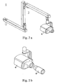
- Figures 1 , 2a and 2b show a typical intra-oral X-ray device (1) which includes a control panel (2), a jointed arm construction (3) and an X-ray source (4).
- Figure 2b shows additionally an elongated collimator (4') which may be attached to the housing of the X-ray source (4) for limiting of the X-ray beam more precisely and thus minimising the radiation dose received by the patient.
- the multielement arm-joint constructions (3) of intra-oral X-ray devices create a lot of degrees of freedom for positioning the X-ray source (4) in a desired manner.
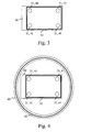
- Figure 3 describes one sensor arrangement usable in the imaging arrangement according to the invention.
- MRI magnetic resonance imaging
- detectors (31) which measure the strength of a magnetic field, are arranged to the intra-oral sensor (30), to the corners of an area forming a rectangle which essentially does not resemble a line.
- a permanent magnet or e.g .
- an inductive transmitter is arranged to the X-ray source (4) or to its essential proximity, signals corresponding the strengths of the magnetic field measured by the MRI detectors (31) are received from them, which signals depend on the position and orientation of the sensor (30) in the magnetic field, such as the distance and the angle of inclination of the detectors (31) with respect to the inductive transmitter or the permanent magnet.
- MRI detectors (31) it is also possible to use small coils (41) and connect to them a means for measuring the signal received from each coil (41), the strength of which signal thus being dependent on the strength of the magnetic field in the position the coil (41) is located at a given time.
- the distance of the sensor (30) and the radiation source (4) with respect to each other is desired to be able to be set the same, repeatedly, and the sensor (30) essentially perpendicularly with respect to the X-ray beam produced by the radiation source (4), and into the middle of it.
- the sensor (30) essentially perpendicularly with respect to the X-ray beam produced by the radiation source (4), and into the middle of it.
- the positioning or the reproductionability of positioning of the sensor (30) and the radiation source (4) with respect to each other may be facilitated already by a single signal received from one MRI detector (31) or coil (42) arranged in connection with the sensor (30), especially if the mutual distance between the sensor (30) and the radiation source (4) may be standardised by some other means.
- signals received from at least three, preferably four different coils (41) or detectors (31) are required.
- they may be preferably arranged e.g. to the corners of an area forming a rectangle which essentially does not resemble a line, and three e. g. to the corners of an area forming essentially an equilateral triangle.
- At least one of the detectors (31) or coils (41) may also be arranged to a different plane or angle with respect to one of their mounting surfaces, with respect to at least one other detector (31) or coil (41), e.g. so that they are arranged perpendicularly with respect to one focus point.
- Signals including measured values representing strengths of the magnetic fields may be sent e.g . to a display device pertaining to the user interface of the control system of the imaging arrangement or some other display device, from which one is able to monitor changing of the values in question when changing the mutual position of the sensor (30) and the X-ray source (4), and deduce from it when the positioning is as desired.
- the arrangement may also include a computer program, e.g . for converting the measured values in question to visually presenting the position of the sensor (30) and the X-ray source (4) with respect to each other on the screen, or some other computer program by means of which one is able to show signal data in a form which facilitates the positioning.
- one preferable embodiment of the invention comprises a solution which utilises an inductive transmitter arranged to the radiation source (4) for other purposes, i.e ., for transmitting energy.
- Such an inductive transmitter, or a coil (42) pertaining therein may be attached or integrated e.g . to an adapter (40) of e.g . ring-like or rectangular shape, to be attached to the collimator (4') of the X-ray source (4).
- Figure 4 shows such an adapter (40) and a coil (42) of an inductive transmitter integrated therein, as positioned with respect to the sensor (30) according to Figure 3 in such a manner one typically tries to position it in connection with intra-oral imaging.
- the adapter (40) may be arranged to be attached to the end of e.g . an X-ray tube (4), or a collimator tube (4') used therein, or as integrated therewith.
- the coil (32) of the inductive receiver is shown in the sensor (30) according to Figures 3 and 4 , which coil may thus be used not only in accordance with one preferable embodiment of the invention to form an energy transmission link e.g . with an inductive transmitter arranged to the X-ray source (4) or its essential proximity, but also in a corresponding manner than described above in connection with corner coils (41), as a signal source to provide data on position of the sensor (30) in the magnetic field produced by the inductive transmitter.
- the coil (32) of the inductive receiver may be arranged as e.g .
- One preferable embodiment of the invention thus comprises an arrangement in which an inductive transmitter is placed in the X-ray source (4), and in which small receiver coils (41) or MRI detectors (31) are arranged e.g . essentially to the corners of a sensor (4) essentially of rectangular shape, or to at least one of them.
- small receiver coils (41) or MRI detectors (31) are arranged e.g . essentially to the corners of a sensor (4) essentially of rectangular shape, or to at least one of them.
- the coil (32) of the inductive receiver may be arranged to be used for this purpose as well.
- These signals may be arranged to be sent e.g . via a wireless link (not shown in Figures 3 and 4 ) such as an RF link, as signals indicating the mutual position of the sensor (30) and the X-ray source (4), which signals may be utilised for achieving a desired mutual position of the sensor (30) and the radiation source (4).
- the invention is described above so that the magnetic field is produced in connection with the radiation source (4), and its strength is measured by a means arranged in connection with the sensor (30).
Landscapes
- Health & Medical Sciences (AREA)
- Life Sciences & Earth Sciences (AREA)
- Medical Informatics (AREA)
- Engineering & Computer Science (AREA)
- Heart & Thoracic Surgery (AREA)
- Molecular Biology (AREA)
- Biophysics (AREA)
- Nuclear Medicine, Radiotherapy & Molecular Imaging (AREA)
- Optics & Photonics (AREA)
- Pathology (AREA)
- Radiology & Medical Imaging (AREA)
- Biomedical Technology (AREA)
- Physics & Mathematics (AREA)
- High Energy & Nuclear Physics (AREA)
- Surgery (AREA)
- Animal Behavior & Ethology (AREA)
- General Health & Medical Sciences (AREA)
- Public Health (AREA)
- Veterinary Medicine (AREA)
- Apparatus For Radiation Diagnosis (AREA)
- Medicines Containing Antibodies Or Antigens For Use As Internal Diagnostic Agents (AREA)
- Magnetic Resonance Imaging Apparatus (AREA)
- Dental Tools And Instruments Or Auxiliary Dental Instruments (AREA)
- Endoscopes (AREA)
Claims (15)
- Mundinnenraumröntgenabbildeanordnung, die eine Strahlungsquelle (4) zum Erzeugen eines beim Abbilden verwendeten Röntgenstrahls und zum Richten des Röntgenstrahls auf das abzubildende Objekt, einen Sensor (30) zum Erfassen von entsprechenden Bilddaten, und ein Steuerungssystem der Abbildeanordnung enthält, dadurch gekennzeichnet, dass eine Einrichtung zum Erzeugen eines Magnetfeldes in Verbindung mit der Strahlungsquelle (4) angeordnet ist, und dadurch dass eine Einrichtung zum Messen der Stärke des magnetischen Feldes in Verbindung mit dem Sensor (30) angeordnet ist.
- Abbildeanordnung nach Anspruch 1, dadurch gekennzeichnet, dass die Einrichtung zum Produzieren eines Magnetfelds ein induktiver Transmitter oder ein Permanentmagnet ist.
- Abbildeanordnung nach Anspruch 1 oder 2, dadurch gekennzeichnet, dass die Einrichtung zum Messen der Stärke des Magnetfeldes zumindest einen MRI Detektor (31) oder eine solche Spule (41, 32) aufweist, mit der in Verbindung eine Einrichtung angeordnet ist, die dafür bekannt ist, dass sie die Stärke des magnetischen Feldes aus einem von der Spule (41, 32) zu empfangenden Signal misst.
- Abbildeanordnung nach Anspruch 3, dadurch gekennzeichnet, dass es drei oder vier der Detektoren (31) oder Spulen (41, 32) gibt.
- Abbildeanordnung nach Anspruch 4, dadurch gekennzeichnet, dass die Detektoren (31) oder Spulen (41, 32) an den Ecken eines Gebiets angeordnet sind, das zumindest ein im Wesentlichen gleichseitiges Dreieck oder ein Rechteck bildet, das im Wesentlichen nicht einer Linie ähnelt.
- Abbildeanordnung nach einem der Ansprüche 3 bis 5, dadurch gekennzeichnet, dass zumindest einer der Detektoren (31) oder Spulen (41, 32) mit Bezug auf zumindest einen anderen Detektor (31) oder eine andere Spule (41, 32) in einer anderen Ebene oder einem anderen Winkel auf einer auf den Sensor (30) bzw. der Strahlungsquelle (4) bezogenen Fläche angeordnet ist.
- Abbildeanordnung nach Anspruch 6, dadurch gekennzeichnet, dass die Detektoren (31) oder Spulen (41, 32) senkrecht mit Bezug auf einen Fokuspunkt angeordnet sind.
- Abbildeanordnung nach einem der Ansprüche 1 bis 7, dadurch gekennzeichnet, dass die Einrichtung zum Erzeugen eines magnetischen Feldes ein induktiver Transmitter ist, der auch angeordnet ist, um dem Sensor (30), der zu der Abbildeanordnung gehört, Energie zuzuführen.
- Abbildeanordnung nach Anspruch 8, dadurch gekennzeichnet, dass der Sensor (30) eine Spule (32) eines induktiven Empfängers aufweist, die im Wesentlichen der Form des Sensorgehäuseumfangs ähnelt.
- Abbildeanordnung nach Anspruch 9, dadurch gekennzeichnet, dass eine als solche bekannte Einrichtung in Verbindung mit der Spule (32) des induktiven Empfängers angeordnet ist, um die Stärke des magnetischen Feldes aus dem von der Spule (41, 32) empfangenen Signal zu messen.
- Abbildeanordnung nach einem der Ansprüche 1 bis 10, dadurch gekennzeichnet, dass sie eine Einrichtung zum Weiterleiten von zumindest einem die Stärke des Magnetfeldes repräsentierenden Signals an ein Anzeigegerät aufweist, das zu der Nutzerschnittstelle des Steuerungssystems der Abbildeanordnung oder zu einem anderen Anzeigegerät gehört.
- Verfahren zum Positionieren einer Röntgenquelle (4) und eines Sensors (30) in Bezug zueinander in Verbindung mit Mundinnenraumröntgenabbildung, wobei zumindest ein Messsignal bei der Positionierung verwendet wird, dadurch gekennzeichnet, dass das Signal durch Anordnen einer Einrichtung zum Erzeugen eines Magnetfelds in Verbindung mit der Strahlungsquelle (4) und durch Anordnen einer Einrichtung zum Messen der Stärke des Magnetfelds in Verbindung mit dem Sensor (30) empfangen wird.
- Verfahren nach Anspruch 12, dadurch gekennzeichnet, dass es drei oder vier Messsignale verwendet.
- Verfahren nach Anspruch 13, dadurch gekennzeichnet, dass die Signale von den Ecken eines Gebiets in dem magnetischen Feld gemessen werden, das zumindest im Wesentlichen eine Form von einem gleichseitigen Dreieck oder einem Rechteck aufweist, das nicht einer Linie ähnelt.
- Verfahren nach einem der Ansprüche 12 bis 14, dadurch gekennzeichnet, dass das magnetische Feld mit einem induktiven Transmitter erzeugt wird, der in Verbindung mit der Strahlungsquelle (4) angeordnet ist.
Applications Claiming Priority (2)
| Application Number | Priority Date | Filing Date | Title |
|---|---|---|---|
| FI20041010A FI118356B (fi) | 2004-07-22 | 2004-07-22 | Järjestely intraoraaliröntgenkuvantamisen yhteydessä |
| PCT/FI2005/000336 WO2006008338A1 (en) | 2004-07-22 | 2005-07-22 | Arrangement in connection with intra-oral x-ray imaging |
Publications (3)
| Publication Number | Publication Date |
|---|---|
| EP1778090A1 EP1778090A1 (de) | 2007-05-02 |
| EP1778090A4 EP1778090A4 (de) | 2010-01-20 |
| EP1778090B1 true EP1778090B1 (de) | 2010-12-22 |
Family
ID=32749227
Family Applications (1)
| Application Number | Title | Priority Date | Filing Date |
|---|---|---|---|
| EP05771106A Expired - Lifetime EP1778090B1 (de) | 2004-07-22 | 2005-07-22 | Anordnung in verbindung mit intraoraler röntgendarstellung |
Country Status (6)
| Country | Link |
|---|---|
| US (1) | US7503692B2 (de) |
| EP (1) | EP1778090B1 (de) |
| AT (1) | ATE492213T1 (de) |
| DE (1) | DE602005025491D1 (de) |
| FI (1) | FI118356B (de) |
| WO (1) | WO2006008338A1 (de) |
Families Citing this family (21)
| Publication number | Priority date | Publication date | Assignee | Title |
|---|---|---|---|---|
| FR2899349B1 (fr) | 2006-04-04 | 2009-05-01 | Pierre Tranchant | Reglage de position d'une installation de radiologie mobile |
| WO2007149402A2 (en) * | 2006-06-16 | 2007-12-27 | Gendex Corporation | Positioning system for dental intra-oral x-ray apparatus |
| JP4974726B2 (ja) * | 2007-03-23 | 2012-07-11 | 富士フイルム株式会社 | 放射線撮像装置、放射線撮像方法、及びプログラム |
| EP2213237A1 (de) * | 2009-01-29 | 2010-08-04 | Vivi S.r.L. | Röntgenvorrichtung umfassend eine Winkelanzeige |
| DE102010008551B4 (de) * | 2010-02-19 | 2020-02-06 | Siemens Healthcare Gmbh | Röntgensystem |
| US8827554B2 (en) * | 2010-04-13 | 2014-09-09 | Carestream Health, Inc. | Tube alignment for mobile radiography system |
| US8821015B2 (en) * | 2011-03-08 | 2014-09-02 | Carestream Health, Inc. | Alignment apparatus for X-ray imaging system |
| FI123713B (fi) * | 2011-03-21 | 2013-09-30 | Planmeca Oy | Järjestely intraoraaliröntgenkuvantamisen yhteydessä |
| FI125516B (fi) * | 2011-03-21 | 2015-11-13 | Planmeca Oy | Kollimaattorijärjestely intraoraaliröntgenkuvantamisen yhteydessä |
| JP2015508011A (ja) | 2012-02-22 | 2015-03-16 | ケアストリーム ヘルス インク | トモシンセシス性能を備えた移動型放射線撮影装置/方法 |
| US20140086389A1 (en) * | 2012-09-12 | 2014-03-27 | Seung H. Baek | Method and apparatus for more accurate positioning of dental imaging equipment |
| US9055923B2 (en) * | 2012-10-19 | 2015-06-16 | Carestream Health, Inc. | Computed radiography positioning method and system |
| US9724055B2 (en) | 2014-03-07 | 2017-08-08 | Elwha Llc | Systems, devices, and methods for lowering dental x-ray dosage including feedback sensors |
| JP6400307B2 (ja) * | 2014-03-10 | 2018-10-03 | キヤノンメディカルシステムズ株式会社 | X線画像診断装置 |
| KR102340197B1 (ko) * | 2015-02-03 | 2021-12-16 | 삼성전자주식회사 | 엑스선 장치 및 엑스선 장치의 동작 방법 |
| US10213180B2 (en) | 2016-09-14 | 2019-02-26 | Dental Imaging Technologies Corporation | Multiple-dimension imaging sensor with operation based on magnetic field detection |
| US10299741B2 (en) | 2016-09-14 | 2019-05-28 | Dental Imaging Technologies Corporation | Multiple-dimension imaging sensor and state-based operation of an imaging system including a multiple-dimension imaging sensor |
| US10299742B2 (en) | 2016-09-14 | 2019-05-28 | Dental Imaging Technologies Corporation | Multiple-dimension imaging sensor with fault condition detection |
| US10932733B2 (en) | 2016-09-14 | 2021-03-02 | Dental Imaging Technologies Corporation | Multiple-dimension imaging sensor with operation based on movement detection |
| JP6938322B2 (ja) * | 2016-10-14 | 2021-09-22 | 株式会社モリタ製作所 | 医療用x線撮影装置の操作パネル表示装置、医療用x線撮影装置、医療用x線撮影装置の操作パネル表示装置における表示方法及び表示プログラム |
| CN117653178B (zh) * | 2024-02-01 | 2024-05-17 | 上海奕瑞光电子科技股份有限公司 | 一种用于x光机的定位方法及定位装置 |
Family Cites Families (14)
| Publication number | Priority date | Publication date | Assignee | Title |
|---|---|---|---|---|
| US4223228A (en) * | 1979-06-21 | 1980-09-16 | Indianapolis Center For Advanced Research | Dental x-ray aligning system |
| SE453047B (sv) | 1981-11-04 | 1988-01-11 | Trollhetteplast Forseljnings A | Hjelpmedel for utforande av tandrontgenundersokningar |
| GB8302980D0 (en) * | 1983-02-03 | 1983-03-09 | Procter & Gamble Ltd | Laundry additive compositions |
| US4554676A (en) | 1983-03-16 | 1985-11-19 | The S. S. White Company | Dental aiming device |
| US5611347A (en) | 1989-07-25 | 1997-03-18 | Smith & Nephew, Inc. | Zirconium oxide and zirconium nitride coated percutaneous devices |
| US5113424A (en) | 1991-02-04 | 1992-05-12 | University Of Medicine & Dentistry Of New Jersey | Apparatus for taking radiographs used in performing dental subtraction radiography with a sensorized dental mouthpiece and a robotic system |
| DE4402114C2 (de) * | 1994-01-25 | 1999-06-02 | Sirona Dental Systems Gmbh | Strahlendetektor mit einem Gehäuse zur Aufnahme eines Strahlungswandlers |
| US5463669A (en) * | 1994-09-08 | 1995-10-31 | Kaplan; Jerome I. | Dental X-ray alignment system |
| DE19619925C2 (de) * | 1996-05-17 | 1999-09-09 | Sirona Dental Systems Gmbh | Röntgendiagnostikgerät für Tomosynthese |
| US5879297A (en) | 1997-05-08 | 1999-03-09 | Lucent Medical Systems, Inc. | System and method to determine the location and orientation of an indwelling medical device |
| US6343875B1 (en) | 1999-06-30 | 2002-02-05 | Dentsply Research & Development Corp. | Modular bite block and sensor holder apparatus for dental x-ray procedures |
| WO2004019783A1 (en) | 2002-08-30 | 2004-03-11 | Dae-Yeun Kim | Intraoral imaging system |
| DE10247940A1 (de) * | 2002-10-15 | 2004-04-29 | Ute Sickinger | Vorrichtung und Verfahren für das intraorale Zahnröntgen |
| WO2007149402A2 (en) * | 2006-06-16 | 2007-12-27 | Gendex Corporation | Positioning system for dental intra-oral x-ray apparatus |
-
2004
- 2004-07-22 FI FI20041010A patent/FI118356B/fi active IP Right Grant
-
2005
- 2005-07-22 EP EP05771106A patent/EP1778090B1/de not_active Expired - Lifetime
- 2005-07-22 US US11/572,459 patent/US7503692B2/en not_active Expired - Lifetime
- 2005-07-22 DE DE602005025491T patent/DE602005025491D1/de not_active Expired - Lifetime
- 2005-07-22 WO PCT/FI2005/000336 patent/WO2006008338A1/en not_active Ceased
- 2005-07-22 AT AT05771106T patent/ATE492213T1/de not_active IP Right Cessation
Also Published As
| Publication number | Publication date |
|---|---|
| US20080002808A1 (en) | 2008-01-03 |
| FI20041010A0 (fi) | 2004-07-22 |
| US7503692B2 (en) | 2009-03-17 |
| EP1778090A4 (de) | 2010-01-20 |
| DE602005025491D1 (de) | 2011-02-03 |
| FI20041010L (fi) | 2006-01-23 |
| ATE492213T1 (de) | 2011-01-15 |
| WO2006008338A1 (en) | 2006-01-26 |
| FI118356B (fi) | 2007-10-15 |
| EP1778090A1 (de) | 2007-05-02 |
Similar Documents
| Publication | Publication Date | Title |
|---|---|---|
| EP1778090B1 (de) | Anordnung in verbindung mit intraoraler röntgendarstellung | |
| US7780350B2 (en) | Positioning adjustment of a mobile radiology facility | |
| EP0782413B1 (de) | System zur positionserfassung mittels einer an einem patientenkopf angebrachten referenzeinheit zur anwendung im medizinischen gebiet | |
| US7744279B2 (en) | Orientation sensing apparatus for radiation imaging system | |
| US6738656B1 (en) | Automatic registration system for use with position tracking an imaging system for use in medical applications | |
| EP1380266B1 (de) | Positions- und Bilderfassung zur Anwendung im medizinischen Gebiet | |
| EP2022403A1 (de) | Ausrichtungsvorrichtung für ein Bilderzeugungssystem | |
| KR100807855B1 (ko) | 치아 화상 진찰 장치 | |
| US20090086926A1 (en) | Exposure centering apparatus for imaging system | |
| EP2617359A1 (de) | Ausrichtungssysteme | |
| CN108463171B (zh) | 放射组件及对准该组件的方法 | |
| JP3135068B2 (ja) | 患者の頭部に固定された基準ユニットを用いた医学的応用に使用される位置追跡及び画像生成システム | |
| EP2908730B1 (de) | Positioniervorrichtung und verfahren für computerradiografie | |
| JP2018051306A (ja) | ロボットx線透視ナビゲーション | |
| JP2010075316A (ja) | 自動較正機能付きステレオバイオプシ装置およびその制御方法 | |
| CN214128491U (zh) | 一种胶囊定位系统 | |
| CN214128485U (zh) | 一种胶囊定位系统 |
Legal Events
| Date | Code | Title | Description |
|---|---|---|---|
| PUAI | Public reference made under article 153(3) epc to a published international application that has entered the european phase |
Free format text: ORIGINAL CODE: 0009012 |
|
| 17P | Request for examination filed |
Effective date: 20070216 |
|
| AK | Designated contracting states |
Kind code of ref document: A1 Designated state(s): AT BE BG CH CY CZ DE DK EE ES FI FR GB GR HU IE IS IT LI LT LU LV MC NL PL PT RO SE SI SK TR |
|
| DAX | Request for extension of the european patent (deleted) | ||
| A4 | Supplementary search report drawn up and despatched |
Effective date: 20091222 |
|
| GRAP | Despatch of communication of intention to grant a patent |
Free format text: ORIGINAL CODE: EPIDOSNIGR1 |
|
| GRAS | Grant fee paid |
Free format text: ORIGINAL CODE: EPIDOSNIGR3 |
|
| GRAA | (expected) grant |
Free format text: ORIGINAL CODE: 0009210 |
|
| AK | Designated contracting states |
Kind code of ref document: B1 Designated state(s): AT BE BG CH CY CZ DE DK EE ES FI FR GB GR HU IE IS IT LI LT LU LV MC NL PL PT RO SE SI SK TR |
|
| REG | Reference to a national code |
Ref country code: GB Ref legal event code: FG4D |
|
| REG | Reference to a national code |
Ref country code: CH Ref legal event code: EP |
|
| REG | Reference to a national code |
Ref country code: IE Ref legal event code: FG4D |
|
| REF | Corresponds to: |
Ref document number: 602005025491 Country of ref document: DE Date of ref document: 20110203 Kind code of ref document: P |
|
| REG | Reference to a national code |
Ref country code: DE Ref legal event code: R096 Ref document number: 602005025491 Country of ref document: DE Effective date: 20110203 |
|
| REG | Reference to a national code |
Ref country code: NL Ref legal event code: VDEP Effective date: 20101222 |
|
| PG25 | Lapsed in a contracting state [announced via postgrant information from national office to epo] |
Ref country code: LT Free format text: LAPSE BECAUSE OF FAILURE TO SUBMIT A TRANSLATION OF THE DESCRIPTION OR TO PAY THE FEE WITHIN THE PRESCRIBED TIME-LIMIT Effective date: 20101222 |
|
| LTIE | Lt: invalidation of european patent or patent extension |
Effective date: 20101222 |
|
| PG25 | Lapsed in a contracting state [announced via postgrant information from national office to epo] |
Ref country code: BG Free format text: LAPSE BECAUSE OF FAILURE TO SUBMIT A TRANSLATION OF THE DESCRIPTION OR TO PAY THE FEE WITHIN THE PRESCRIBED TIME-LIMIT Effective date: 20110322 Ref country code: SI Free format text: LAPSE BECAUSE OF FAILURE TO SUBMIT A TRANSLATION OF THE DESCRIPTION OR TO PAY THE FEE WITHIN THE PRESCRIBED TIME-LIMIT Effective date: 20101222 Ref country code: SE Free format text: LAPSE BECAUSE OF FAILURE TO SUBMIT A TRANSLATION OF THE DESCRIPTION OR TO PAY THE FEE WITHIN THE PRESCRIBED TIME-LIMIT Effective date: 20101222 Ref country code: LV Free format text: LAPSE BECAUSE OF FAILURE TO SUBMIT A TRANSLATION OF THE DESCRIPTION OR TO PAY THE FEE WITHIN THE PRESCRIBED TIME-LIMIT Effective date: 20101222 Ref country code: AT Free format text: LAPSE BECAUSE OF FAILURE TO SUBMIT A TRANSLATION OF THE DESCRIPTION OR TO PAY THE FEE WITHIN THE PRESCRIBED TIME-LIMIT Effective date: 20101222 Ref country code: CY Free format text: LAPSE BECAUSE OF FAILURE TO SUBMIT A TRANSLATION OF THE DESCRIPTION OR TO PAY THE FEE WITHIN THE PRESCRIBED TIME-LIMIT Effective date: 20101222 Ref country code: FI Free format text: LAPSE BECAUSE OF FAILURE TO SUBMIT A TRANSLATION OF THE DESCRIPTION OR TO PAY THE FEE WITHIN THE PRESCRIBED TIME-LIMIT Effective date: 20101222 |
|
| PG25 | Lapsed in a contracting state [announced via postgrant information from national office to epo] |
Ref country code: CZ Free format text: LAPSE BECAUSE OF FAILURE TO SUBMIT A TRANSLATION OF THE DESCRIPTION OR TO PAY THE FEE WITHIN THE PRESCRIBED TIME-LIMIT Effective date: 20101222 Ref country code: PT Free format text: LAPSE BECAUSE OF FAILURE TO SUBMIT A TRANSLATION OF THE DESCRIPTION OR TO PAY THE FEE WITHIN THE PRESCRIBED TIME-LIMIT Effective date: 20110422 Ref country code: IS Free format text: LAPSE BECAUSE OF FAILURE TO SUBMIT A TRANSLATION OF THE DESCRIPTION OR TO PAY THE FEE WITHIN THE PRESCRIBED TIME-LIMIT Effective date: 20110422 Ref country code: GR Free format text: LAPSE BECAUSE OF FAILURE TO SUBMIT A TRANSLATION OF THE DESCRIPTION OR TO PAY THE FEE WITHIN THE PRESCRIBED TIME-LIMIT Effective date: 20110323 Ref country code: ES Free format text: LAPSE BECAUSE OF FAILURE TO SUBMIT A TRANSLATION OF THE DESCRIPTION OR TO PAY THE FEE WITHIN THE PRESCRIBED TIME-LIMIT Effective date: 20110402 Ref country code: BE Free format text: LAPSE BECAUSE OF FAILURE TO SUBMIT A TRANSLATION OF THE DESCRIPTION OR TO PAY THE FEE WITHIN THE PRESCRIBED TIME-LIMIT Effective date: 20101222 Ref country code: EE Free format text: LAPSE BECAUSE OF FAILURE TO SUBMIT A TRANSLATION OF THE DESCRIPTION OR TO PAY THE FEE WITHIN THE PRESCRIBED TIME-LIMIT Effective date: 20101222 |
|
| PG25 | Lapsed in a contracting state [announced via postgrant information from national office to epo] |
Ref country code: SK Free format text: LAPSE BECAUSE OF FAILURE TO SUBMIT A TRANSLATION OF THE DESCRIPTION OR TO PAY THE FEE WITHIN THE PRESCRIBED TIME-LIMIT Effective date: 20101222 Ref country code: NL Free format text: LAPSE BECAUSE OF FAILURE TO SUBMIT A TRANSLATION OF THE DESCRIPTION OR TO PAY THE FEE WITHIN THE PRESCRIBED TIME-LIMIT Effective date: 20101222 Ref country code: RO Free format text: LAPSE BECAUSE OF FAILURE TO SUBMIT A TRANSLATION OF THE DESCRIPTION OR TO PAY THE FEE WITHIN THE PRESCRIBED TIME-LIMIT Effective date: 20101222 Ref country code: PL Free format text: LAPSE BECAUSE OF FAILURE TO SUBMIT A TRANSLATION OF THE DESCRIPTION OR TO PAY THE FEE WITHIN THE PRESCRIBED TIME-LIMIT Effective date: 20101222 |
|
| PLBE | No opposition filed within time limit |
Free format text: ORIGINAL CODE: 0009261 |
|
| STAA | Information on the status of an ep patent application or granted ep patent |
Free format text: STATUS: NO OPPOSITION FILED WITHIN TIME LIMIT |
|
| PG25 | Lapsed in a contracting state [announced via postgrant information from national office to epo] |
Ref country code: DK Free format text: LAPSE BECAUSE OF FAILURE TO SUBMIT A TRANSLATION OF THE DESCRIPTION OR TO PAY THE FEE WITHIN THE PRESCRIBED TIME-LIMIT Effective date: 20101222 |
|
| 26N | No opposition filed |
Effective date: 20110923 |
|
| PG25 | Lapsed in a contracting state [announced via postgrant information from national office to epo] |
Ref country code: IT Free format text: LAPSE BECAUSE OF FAILURE TO SUBMIT A TRANSLATION OF THE DESCRIPTION OR TO PAY THE FEE WITHIN THE PRESCRIBED TIME-LIMIT Effective date: 20101222 |
|
| REG | Reference to a national code |
Ref country code: DE Ref legal event code: R097 Ref document number: 602005025491 Country of ref document: DE Effective date: 20110923 |
|
| PG25 | Lapsed in a contracting state [announced via postgrant information from national office to epo] |
Ref country code: MC Free format text: LAPSE BECAUSE OF NON-PAYMENT OF DUE FEES Effective date: 20110731 |
|
| REG | Reference to a national code |
Ref country code: CH Ref legal event code: PL |
|
| REG | Reference to a national code |
Ref country code: IE Ref legal event code: MM4A |
|
| PG25 | Lapsed in a contracting state [announced via postgrant information from national office to epo] |
Ref country code: LI Free format text: LAPSE BECAUSE OF NON-PAYMENT OF DUE FEES Effective date: 20110731 Ref country code: CH Free format text: LAPSE BECAUSE OF NON-PAYMENT OF DUE FEES Effective date: 20110731 |
|
| PG25 | Lapsed in a contracting state [announced via postgrant information from national office to epo] |
Ref country code: IE Free format text: LAPSE BECAUSE OF NON-PAYMENT OF DUE FEES Effective date: 20110722 |
|
| PG25 | Lapsed in a contracting state [announced via postgrant information from national office to epo] |
Ref country code: LU Free format text: LAPSE BECAUSE OF NON-PAYMENT OF DUE FEES Effective date: 20110722 |
|
| PG25 | Lapsed in a contracting state [announced via postgrant information from national office to epo] |
Ref country code: TR Free format text: LAPSE BECAUSE OF FAILURE TO SUBMIT A TRANSLATION OF THE DESCRIPTION OR TO PAY THE FEE WITHIN THE PRESCRIBED TIME-LIMIT Effective date: 20101222 |
|
| PG25 | Lapsed in a contracting state [announced via postgrant information from national office to epo] |
Ref country code: HU Free format text: LAPSE BECAUSE OF FAILURE TO SUBMIT A TRANSLATION OF THE DESCRIPTION OR TO PAY THE FEE WITHIN THE PRESCRIBED TIME-LIMIT Effective date: 20101222 |
|
| REG | Reference to a national code |
Ref country code: FR Ref legal event code: PLFP Year of fee payment: 12 |
|
| REG | Reference to a national code |
Ref country code: FR Ref legal event code: PLFP Year of fee payment: 13 |
|
| REG | Reference to a national code |
Ref country code: FR Ref legal event code: PLFP Year of fee payment: 14 |
|
| PGFP | Annual fee paid to national office [announced via postgrant information from national office to epo] |
Ref country code: GB Payment date: 20220622 Year of fee payment: 18 |
|
| PGFP | Annual fee paid to national office [announced via postgrant information from national office to epo] |
Ref country code: FR Payment date: 20220622 Year of fee payment: 18 |
|
| PGFP | Annual fee paid to national office [announced via postgrant information from national office to epo] |
Ref country code: DE Payment date: 20220621 Year of fee payment: 18 |
|
| REG | Reference to a national code |
Ref country code: DE Ref legal event code: R079 Ref document number: 602005025491 Country of ref document: DE Free format text: PREVIOUS MAIN CLASS: A61B0006140000 Ipc: A61B0006510000 |
|
| REG | Reference to a national code |
Ref country code: DE Ref legal event code: R119 Ref document number: 602005025491 Country of ref document: DE |
|
| GBPC | Gb: european patent ceased through non-payment of renewal fee |
Effective date: 20230722 |
|
| PG25 | Lapsed in a contracting state [announced via postgrant information from national office to epo] |
Ref country code: DE Free format text: LAPSE BECAUSE OF NON-PAYMENT OF DUE FEES Effective date: 20240201 Ref country code: GB Free format text: LAPSE BECAUSE OF NON-PAYMENT OF DUE FEES Effective date: 20230722 |
|
| PG25 | Lapsed in a contracting state [announced via postgrant information from national office to epo] |
Ref country code: FR Free format text: LAPSE BECAUSE OF NON-PAYMENT OF DUE FEES Effective date: 20230731 |