EP1778110B1 - Gerät zur korrektor von skelettdeformitäten - Google Patents
Gerät zur korrektor von skelettdeformitäten Download PDFInfo
- Publication number
- EP1778110B1 EP1778110B1 EP05753193.1A EP05753193A EP1778110B1 EP 1778110 B1 EP1778110 B1 EP 1778110B1 EP 05753193 A EP05753193 A EP 05753193A EP 1778110 B1 EP1778110 B1 EP 1778110B1
- Authority
- EP
- European Patent Office
- Prior art keywords
- rod
- implantable apparatus
- receiving member
- rod receiving
- attachment
- Prior art date
- Legal status (The legal status is an assumption and is not a legal conclusion. Google has not performed a legal analysis and makes no representation as to the accuracy of the status listed.)
- Expired - Lifetime
Links
Images





Classifications
-
- A—HUMAN NECESSITIES
- A61—MEDICAL OR VETERINARY SCIENCE; HYGIENE
- A61B—DIAGNOSIS; SURGERY; IDENTIFICATION
- A61B17/00—Surgical instruments, devices or methods
- A61B17/56—Surgical instruments or methods for treatment of bones or joints; Devices specially adapted therefor
- A61B17/58—Surgical instruments or methods for treatment of bones or joints; Devices specially adapted therefor for osteosynthesis, e.g. bone plates, screws or setting implements
- A61B17/68—Internal fixation devices, including fasteners and spinal fixators, even if a part thereof projects from the skin
- A61B17/80—Cortical plates, i.e. bone plates; Instruments for holding or positioning cortical plates, or for compressing bones attached to cortical plates
- A61B17/8004—Cortical plates, i.e. bone plates; Instruments for holding or positioning cortical plates, or for compressing bones attached to cortical plates with means for distracting or compressing the bone or bones
-
- A—HUMAN NECESSITIES
- A61—MEDICAL OR VETERINARY SCIENCE; HYGIENE
- A61B—DIAGNOSIS; SURGERY; IDENTIFICATION
- A61B17/00—Surgical instruments, devices or methods
- A61B17/56—Surgical instruments or methods for treatment of bones or joints; Devices specially adapted therefor
- A61B17/58—Surgical instruments or methods for treatment of bones or joints; Devices specially adapted therefor for osteosynthesis, e.g. bone plates, screws or setting implements
- A61B17/68—Internal fixation devices, including fasteners and spinal fixators, even if a part thereof projects from the skin
- A61B17/683—Internal fixation devices, including fasteners and spinal fixators, even if a part thereof projects from the skin comprising bone transfixation elements, e.g. bolt with a distal cooperating element such as a nut
-
- A—HUMAN NECESSITIES
- A61—MEDICAL OR VETERINARY SCIENCE; HYGIENE
- A61B—DIAGNOSIS; SURGERY; IDENTIFICATION
- A61B17/00—Surgical instruments, devices or methods
- A61B17/56—Surgical instruments or methods for treatment of bones or joints; Devices specially adapted therefor
- A61B17/58—Surgical instruments or methods for treatment of bones or joints; Devices specially adapted therefor for osteosynthesis, e.g. bone plates, screws or setting implements
- A61B17/68—Internal fixation devices, including fasteners and spinal fixators, even if a part thereof projects from the skin
- A61B17/70—Spinal positioners or stabilisers, e.g. stabilisers comprising fluid filler in an implant
- A61B17/7001—Screws or hooks combined with longitudinal elements which do not contact vertebrae
-
- A—HUMAN NECESSITIES
- A61—MEDICAL OR VETERINARY SCIENCE; HYGIENE
- A61B—DIAGNOSIS; SURGERY; IDENTIFICATION
- A61B17/00—Surgical instruments, devices or methods
- A61B17/56—Surgical instruments or methods for treatment of bones or joints; Devices specially adapted therefor
- A61B17/58—Surgical instruments or methods for treatment of bones or joints; Devices specially adapted therefor for osteosynthesis, e.g. bone plates, screws or setting implements
- A61B17/68—Internal fixation devices, including fasteners and spinal fixators, even if a part thereof projects from the skin
- A61B17/70—Spinal positioners or stabilisers, e.g. stabilisers comprising fluid filler in an implant
- A61B17/7001—Screws or hooks combined with longitudinal elements which do not contact vertebrae
- A61B17/7002—Longitudinal elements, e.g. rods
- A61B17/7011—Longitudinal element being non-straight, e.g. curved, angled or branched
-
- A—HUMAN NECESSITIES
- A61—MEDICAL OR VETERINARY SCIENCE; HYGIENE
- A61B—DIAGNOSIS; SURGERY; IDENTIFICATION
- A61B17/00—Surgical instruments, devices or methods
- A61B17/56—Surgical instruments or methods for treatment of bones or joints; Devices specially adapted therefor
- A61B17/58—Surgical instruments or methods for treatment of bones or joints; Devices specially adapted therefor for osteosynthesis, e.g. bone plates, screws or setting implements
- A61B17/68—Internal fixation devices, including fasteners and spinal fixators, even if a part thereof projects from the skin
- A61B17/70—Spinal positioners or stabilisers, e.g. stabilisers comprising fluid filler in an implant
- A61B17/7001—Screws or hooks combined with longitudinal elements which do not contact vertebrae
- A61B17/7002—Longitudinal elements, e.g. rods
- A61B17/7019—Longitudinal elements having flexible parts, or parts connected together, such that after implantation the elements can move relative to each other
- A61B17/7025—Longitudinal elements having flexible parts, or parts connected together, such that after implantation the elements can move relative to each other with a sliding joint
-
- A—HUMAN NECESSITIES
- A61—MEDICAL OR VETERINARY SCIENCE; HYGIENE
- A61B—DIAGNOSIS; SURGERY; IDENTIFICATION
- A61B17/00—Surgical instruments, devices or methods
- A61B17/56—Surgical instruments or methods for treatment of bones or joints; Devices specially adapted therefor
- A61B17/58—Surgical instruments or methods for treatment of bones or joints; Devices specially adapted therefor for osteosynthesis, e.g. bone plates, screws or setting implements
- A61B17/68—Internal fixation devices, including fasteners and spinal fixators, even if a part thereof projects from the skin
- A61B17/70—Spinal positioners or stabilisers, e.g. stabilisers comprising fluid filler in an implant
- A61B17/7001—Screws or hooks combined with longitudinal elements which do not contact vertebrae
- A61B17/7044—Screws or hooks combined with longitudinal elements which do not contact vertebrae also having plates, staples or washers bearing on the vertebrae
-
- A—HUMAN NECESSITIES
- A61—MEDICAL OR VETERINARY SCIENCE; HYGIENE
- A61B—DIAGNOSIS; SURGERY; IDENTIFICATION
- A61B17/00—Surgical instruments, devices or methods
- A61B17/56—Surgical instruments or methods for treatment of bones or joints; Devices specially adapted therefor
- A61B17/58—Surgical instruments or methods for treatment of bones or joints; Devices specially adapted therefor for osteosynthesis, e.g. bone plates, screws or setting implements
- A61B17/68—Internal fixation devices, including fasteners and spinal fixators, even if a part thereof projects from the skin
- A61B17/70—Spinal positioners or stabilisers, e.g. stabilisers comprising fluid filler in an implant
- A61B17/7001—Screws or hooks combined with longitudinal elements which do not contact vertebrae
- A61B17/7002—Longitudinal elements, e.g. rods
- A61B17/701—Longitudinal elements with a non-circular, e.g. rectangular, cross-section
Definitions
- the invention relates to apparatus for correcting skeletal deformities, and in particular to an implantable device for controlling the relationship of bones on either side of a growth plate in paediatrics, and in adults to assist in holding bones in a locked configuration.
- a number of conditions give rise to paediatric deformity, for example scoliosis (or curvature of the spine), club foot, post traumatic deformity such as cubitus varus, knock knees, etc.
- US4,697,582 , WO02/17803 A2 , FR2,709,245 A1 , US6,193,720 B1 (the preamble of claim 1 is based on this document) and WO02/43602 A1 each describe devices where the position of the rod is fixed with respect to at least one rod receiving member.
- the Luque trolley system is described in French published patent application No 2589716 comprises a pair of U-shaped callipers fixed to the spine, one of the callipers sliding within the other so that the spine may grow.
- One problem with this system is that the vertebrae of the spine may fuse spontaneously as a result of exposing the spine to fit the callipers.
- rods are inserted in a way that causes fusion of a small segment of spine proximally and distally to give a solid anchor for the rods.
- the rods do not control the sagital profile adequately and obtain their correction solely by distraction.
- the patient In order to lengthen the rods to accommodate growth, the patient must be operated on every six months or so.
- the purpose of the pediatric ISOLA ® is to stabilize the deformity. Definitive treatment of the scoliosis usually involves a further operation where vertebrae are fused together. Insertion of posterior growing rods and the final fusion procedure are relatively major surgical procedures especially if a thoracotomy is required for anterior release of the curve prior to insertion of the growing rods.
- Factors for the development of early onset scoliosis vary considerably and include idiopathic and neuromuscular aetioligies.
- Growth plates are affected by mechanical stimuli. Increased pressure on a growth plate reduces growth rate, whilst decreased pressure on a growth plate or traction can increase growth rate.
- the spine grows asymmetrically and the deformity is exacerbated.
- treatment aims are to: correct the deformity early, correct the deformity fully, and to hold the correction until growth stops.
- Two categories of the condition can be identified: those that are easy to correct, where correction is by splintage alone; and those that are resistant to correction, where response to splintage is poor and early operative correction is required.
- Operative correction requires the cutting of tendons and ligaments, which aside from post operative complications, tends to result in the foot being stiff in the long term.
- an implantable apparatus as specified in Claim 1.
- an implantable apparatus according to Claim 18.
- a corrective apparatus is attached to adjacent vertebrae 2 of a spine with scoliosis.
- Each vertebrae 2 includes a growth plate 3.
- a screw 4 having a head 5 is attached to each of the vertebrae 2.
- a bore is first drilled through the vertebrae, and then the screw is inserted into the bore.
- the screws 4 are hydroxyapatite coated to provide a biological fix capable of being maintained over several years.
- the screws have a shallow thread depth and a long pitch. The shallow thread depth allows maximum screw strength for a given screw diameter and facilitates screw removal as each screw is over-drilled prior to removal. The only difference between the screw of apparatus 1 and screws currently used for attachment to bone lies in the head 5.
- the screw head 5 is provided with attachment means for attachment of a slide element 6 including an internal bore 7 in which a rod 8 slides (see Figures 7a to 7f for a more detailed description).
- the rod 8 is curved, the radius of curvature being calculated to correct the angle of curvature a of the spine between the adjacent vertebrae shown.
- the slide elements 6 are set at an angle to the screw heads 5. The angle is ⁇ /2. This provides the maximum room for the rod 8, and therefore permits rods having smaller radii of curvature (i.e. more aggressive correction) than if the slide elements are on axis with the screw heads 5, and the angle of curvature ⁇ is taken up by the rod 8 alone.
- the adjacent vertebrae grow resulting in the distance between the screws 4 increasing.
- the slide elements 6 are attached to the screw heads 5, the distance between the two slide elements increases.
- a spine with a scoliosis curve is fitted with apparatus 1, as shown in Figure 1 and 2 , between each adjacent vertebrae.
- the angle between adjacent vertebrae ranges between 0 - 5 degrees in the lower section A of the spine, 0 to 2 degrees in the mid section B, and 5 to 10 degrees in the upper section C of the spine.
- any individual rod between adjacent vertebrae can be selected to match the degree of angular deformity at that location, thereby providing for much more refined treatment of scoliosis than is possible with apparatus of the prior art
- the force due to growth on any one screw 4 (fixation point) is only the force exerted by one growth plate, and therefore is comparatively small
- the fixation points proximally and distally rods would have to withstand the force due to growth generated by each of the growth plates, and would result in comparatively large forces on the fixation points.
- the force generated by each growth plate is harnessed locally in the construct spreading the forces on the screws 4 (the fixation elements) evenly.
- FIG 3 the vertebrae X and X" are separated by a vertebra X'.
- Apparatus 1 is fitted to the vertebrae X and X".
- Vertebra X' is fitted with an attachment (illustrated in Figure 3b ) comprising a threaded shank 4a and a head in the form of an eye 5a.
- the rod 8 slides in the eye 5a and a corrective force is exerted on the vertebra X'.
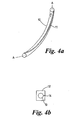
- the rod 10 comprises a track 11.
- a slide element 12 In Figure 4b , there is shown a slide element 12.
- the bore 13 in which the rod 10 slides includes a channel 14 in which the track 11 slides.
- the track 11 has a pitch so that as the rod 10 is drawn out of the slide element 12 the rod is caused to rotate about its own axis A-A.
- This feature allows for the apparatus of the invention to correct rotational misalignment between adjacent vertebrae.
- in order to correct for rotational misalignment there must be no rotational movement between the rod and the slide element in which the rod is located.
- the rod could have a non-circular cross-section, for example square, and this could run in a slide element having a correspondingly shaped bore.
- the rod 10 illustrated in Figure 4a is marked at each end with indicia to tell the surgeon which way round the rod should be inserted.
- the arrow points towards the apex of the scolosis.
- Figures 5a to 5d assist in explaining how the apparatus of the invention can be used to correct skeletal misalignments other than in the spine.
- Figure 5a illustrates a normal foot, where the bones of the lateral ray (see Figure 5c ) lie on an axis L-L, and the bones of the medial ray (see Figure 5d ) lie on an axis M-M.
- Figure 5b illustrates a club foot, where instead of all the bones of the lateral ray lying on the axis L-L, only the calcaneus 21 of the lateral ray lies on this axis, the cuboid 22 and metatarsal 23 lying on an axis L'-L' set at an angle Y to the axis L-L.
- the medial ray instead of all the bones 24 to 27 thereof lying on the axis M-M, only the talus 24 of the medial ray lies on this axis.
- the navicular 25, the inner cuneiform 26 and the metatarsal 27 lie on an axis M'-M' set at an angle Z to the axis M-M.
- the misalignment of the lateral and medial rays of the club foot illustrated in Figure 5b can be corrected by attaching the apparatus 1 illustrated in Figures 1 to 4 to the bones 21 and 22 of the lateral ray and bones 24 and 25 of the medial ray.
- the radius of curvature of the rod 8 and bores 7 must be selected to match the angle of misalignment Y or Z respectively.
- the forefoot supination pronation profile could be corrected by a rotational component built into the rod.
- the rotational misalignment between the talus and calcaneus in club foot could be corrected by an arrangement of the type illustrated in Figure 4a, 4b is required.
- the relationship of the talus to the tibia could also be addressed.
- the apparatus of the invention can also be used to correct some deformities occurring within a bone.
- some conditions such as Perthes disease and developmental dysplasia of the hip (DDH) lead to rotation of the femur, which currently is corrected by breaking the femur, rotating one part of the broken femur relative to the other and re-joining the two parts of the bone.
- DDH developmental dysplasia of the hip
- As part of treatment for various diseases reshaping the femur may be desirable. Instead of performing a varus derotation osteotomy the same effect could be obtained gradually using this device.
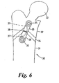
- the femur 30 comprises an upper part 32 which includes the ball part 33 of the ball and socket hip joint, and a lower part 31.
- the lower and upper parts 31, 32 are either side of a growth plate 34.
- the apparatus of the invention can be used to generate a torsional force on the femur, which can be used to correct a developing torsional deformity.
- a screw 35 is inserted into each of the lower and upper parts 31, 32 of the femur. Attached to these screws are slide elements 36, each including a bore 37 in which a curved rod slides.
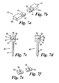
- Figures 7a to 7f illustrate a locking arrangement for locking a slide element to a screw.
- Figure 7a illustrates a slide element 40. Extending from one end thereof is a first part of a locking element, which consists of a semi-circular portion 41 having a bore 42 located in its flat surface.
- Figure 7 b illustrates a second slide element 43. Extending from one end is the second part of the locking element, which consists of a semi-circular portion 44 having a protrusion 45 extending from its flat surface.
- the protrusion 45 is dimensions so as to mate with the bore 42.
- the main body 42a of the slide element 40 may be set at an angle to the semi-circular portion 41, and likewise the main body 44a of the slide element 43 may be set at an angle to the semi-circular portion 44.
- a range of slide elements may be produced, the angle between the main body and the semi-circular portion that engages with the screw head 48 being different.
- a slide element would then be selected to match the angular displacement of the bones whose position is to be corrected.
- Figures 7c and 7d illustrate a screw 46 having a threaded shaft 47 and a head 48.
- a pair of slide elements 40, 43 is attached to the screw 46 illustrated in Figures 7c and 7d .
- the screw head 48 includes a semi-arcular surface 51 upon which the outer surface of the first locking element rests.
- the first and second locking elements 41, 44 and hence the slide elements 40 and 43 of which they form a part are held tightly in the screw head 48 by an externally threaded nut 50 which mates with an internally threaded wall 49 of the said screw head 48.
- Figures 7e and 7f illustrate first and second end pieces 51 and 53 including a protrusion 52 and bore 54 respectively.
- the protrusion 52 of end piece 51 engages with the bore 42 of slide element 40, so that the slide element can be locked to a screw head 48 without the attachment of the slide element 43.
- the protrusion 45 of the slide element 43 engages with the bore 54 of the end piece 53, so that the slide element 43 can be locked in place in a screw head.
- the screw head and the outer surfaces of the locking elements must not allow rotation therebetween. This could be achieved by making the semi-circular surfaces 42, 44 and the inner surface 55 of the screw head rectangular for instance.
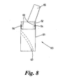
- Figure 8 illustrates a slide element 60 including a bore 62 in which a rod may slide.
- the slide element 60 has a main body 61 and an end piece 62 mounted telescopically therein.
- the end piece 62 includes grooves 63 which engage with protrusions 64 to define the direction in which the end piece may move, and the extent of such movement
- the end piece 62 also mounts an element 65 which locks into a screw head in a similar manner to that illustrated in Figures 7a to 7f .
- the apparatus is fitted to a patient such that the end-piece is fully extended. When the bones to which the apparatus is fitted are under load, for example when standing, the end piece 62 slides into the main body 61. This ensures that the bones carry load, which is important to minimise stress shielding of the bone and reduce stresses on the implant.
- the apparatus of the invention may be used on adults where no growth is expected, in which case the rods are fixed, rather than slidable, with respect to the screws fixed to the bones.
- the apparatus would typically be used in operations to fuse together vertebrae and its purpose would be to hold the spine in the desired shape whilst the vertebrae fused together.
- the apparatus illustrated in Figures 9a and 9b comprises a first element 100 which includes a bore 102 and a second element 101 which includes a rod 103.
- the rod 103 slides in the bore 102 and is attached to a block 104 which is itself attachable to a vertebrae in the same manner as illustrated in Figure 1 .
- a threaded bore 105 is provided in wall 106 of the first element 100, the threaded bore 105 receiving a grub screw 107 that is adjustable to either permit or prevent the rod 103 sliding in the bore 102.
- the first and second elements 100, 101 are attached to fixation points provided by fixation device, such as those illustrated in Figures 1 and 2 .
- the second element 101 is typically attached to a fixation point below the fixation point to which the first element 100 in the bore 102 of which the rod 103 slides. As the person grows, the deformity is corrected due to the angle of curvature of the rod.
- the corrective effect of the device may be reduced or removed by providing one or both ends of the rod with a taper which permits lateral movement between the rod and the bore in which it slides.
- deformity correction is achieved by placing the device in under tension, that is adjacent vertebrae are brought together and the device fitted achieving as much correction as is possible at implantation, and then the residual deformity correction is achieved by 5mm of growth at that motion segment.
- Deformity in the coronal plane and control of extent of kyphosis or lordosis (saggittal plane) is achieved by cutting the rod and bore(s) in an arc such that 5mm movement along the circumference of the arc/circle would give the appropriate angular correction.
- 5mm movement 20 degrees correction was required with 5mm movement:
- any corrective angle can be calculated for a movement of a particular distance.
- Rotational correction is addressed by means of a spiral in the rod and bore (see Figures 4a and 4b ).
- the distances between the screws after insertion and tensioning would be expected to be about 2cm in the thoracic spine and 3cm in the lumbar spine in young adolescents and correspondingly smaller in younger children.
- the screw diameter used in the vertebral body would be as large as possible for maximum strength and need at least 12mm of length in each rod to attach to the modular rod. (assuming 9mm screw with 3mm extra for locking mechanism)
- a lordoscoliosis a few degrees of kyphosis would be desirable at each level and also a few degrees of rotation would be desirable.
- the device of the invention may also be used in the correction of scoliosis in skeletally mature patients.
- the correction of scoliosis with modem pedicle screw, hook, rod systems is achieved by loading the spine to reduce it to the desired configuration using a combination of stress relaxation of the tissues and flexibility of the deformity to achieve correction.
- These instrumentation systems do not however allow accurate segmental correction, eg the rod rotation technique does not derotate the spine but rather tends to rotate it more in the direction of the deformity.
- the device of the invention described for use as a growing rod can be used as a means of accurately realigning spinal segments in adult scoliosis correction.
- the device is designed so that when it is extended it fits on to the deformed spine between adjacent vertebral fixation points, such as pedicle screws (see Figure 9a ).
- the rod When the rod is compressed it shortens and realigns the segments to the desired configuration ( Figure 9b ). It is then locked in this configuration using the grub screw 107.
- the realignment of the spinal segments can be performed in the coronal, saggittal and rotational planes simultaneously using this method.
- the device used at a particular level will give the required saggittal profile for that segment and derotate and compress the segment so as to achieve a near anatomical spinal alignment.
- the device of the invention allows the spine to be realigned much more accurately on a segmental basis with derotation at each level. Moreover the spine could always be instrumented on the convex side first where the pedicles are larger and stronger and further away from the spinal cord. Segmental correction as described could give a better cosmetic result by derotating the ribs helping reduce the size of the residual rib hump and would allow each level to be adjusted several times to gain the maximum curve reduction by better utilising the stress relaxation properties of the spine. For example, using the apparatus illustrated in Figures 9a and 9b , the deformity between adjacent vertebrae could be corrected as far as is possible and the grub screw 107 tightened. The tissues around the vertebrae then relax permitting further correction of the deformity.
- the device When used in the correction of deformity in skeletally mature patients the device may be made of titanium, which is the material commonly used in scoliosis implants, as the implant is used in a locked configuration and hence no bearing/movement is involved once the procedure has been completed. Also its bearing surfaces do not need to be highly polished (as they would need to be in the growing rod implant).
- This implant system of the invention can be applied to the deformed spine and then gradually tensioned to slowly and systematically reduce the spinal deformity. This will make reduction of large curves easier as the difficulties with reducing the spine to the rod and the risk of implant pullout in that process will be greatly reduced.
- the instrumented spine can be tensioned at each level and a gradual reduction achieved with avoidance of stress peaks on individual bone fixation points and more fully utilising the spine's stress relaxation properties.
- This technique may be of particular benefit in procedures where a vertebrectomy has been required.
- the implant would provide stability during the vertebrectomy and then allow a gradual controlled reduction.
Landscapes
- Health & Medical Sciences (AREA)
- Orthopedic Medicine & Surgery (AREA)
- Life Sciences & Earth Sciences (AREA)
- Surgery (AREA)
- Neurology (AREA)
- Heart & Thoracic Surgery (AREA)
- Engineering & Computer Science (AREA)
- Biomedical Technology (AREA)
- Nuclear Medicine, Radiotherapy & Molecular Imaging (AREA)
- Medical Informatics (AREA)
- Molecular Biology (AREA)
- Animal Behavior & Ethology (AREA)
- General Health & Medical Sciences (AREA)
- Public Health (AREA)
- Veterinary Medicine (AREA)
- Surgical Instruments (AREA)
- Prostheses (AREA)
Claims (19)
- Implantierbare Vorrichtung (1) zur Verwendung bei der Korrektur von Skelettdeformitäten, wobei die Vorrichtung einen Stab (8, 10, 38) und ein Paar voneinander beabstandeter Befestigungselemente (4, 35, 46) umfasst, wobei jedes der Befestigungselemente an einem Knochen befestigt werden kann, wobei jedes Befestigungselement (4, 35, 46) ein Stabaufnahmeelement (6, 36, 40, 60) montiert und der Stab (8, 10, 38) in dem Stabaufnahmeelement (6, 36, 40, 60) montiert wird, dadurch gekennzeichnet, dass der Stab (8, 10, 38) gekrümmt ist und jedes Stabaufnahmeelement (6, 36, 40, 60) eine gekrümmte Bohrung (7, 37, 62) umfasst, die dem gekrümmten Stab (8, 10, 38) entspricht, so dass der Stab (8, 10, 38) entlang einem vorher festgelegten Pfad in Bezug auf jedes der Stabaufnahmeelemente (6, 36, 40, 60) gleiten gelassen werden kann.
- Implantierbare Vorrichtung nach Anspruch 1, wobei der Stab (10) und/oder mindestens eines der Stabaufnahmeelemente (6) Mittel (11, 14) zur Verhinderung einer Drehung des Stabs in dem oder jedem Stabaufnahmeelement umfasst.
- Implantierbare Vorrichtung nach Anspruch 2, wobei das besagte Mittel zur Verhinderung einer Drehung des Stabs in dem oder jedem Aufnahmeelement eine Schiene (11), die auf dem Stab montiert ist, und eine Kerbe (14) in dem Stabaufnahmeelement (6), in der die Schiene (11) gleitet, umfasst.
- Implantierbare Vorrichtung nach Anspruch 3, wobei die Schiene (11) zu einer Spirale geformt ist.
- Implantierbare Vorrichtung nach Anspruch 3, wobei der Stab (8) einen nicht kreisförmigen Querschnitt hat und in einem entsprechend geformten Element gleitet.
- Implantierbare Vorrichtung nach Anspruch 1, wobei ein Stabaufnahmeelement (60) mehrere Abschnitte aufweist, wobei einer teleskopisch in den anderen gleiten gelassen werden kann.
- Implantierbare Vorrichtung nach Anspruch 6, wobei die Abschnitte Mittel zum Verhindern einer Drehung eines Stababschnitts in Bezug auf einen anderen aufweisen.
- Implantierbare Vorrichtung nach einem vorhergehenden Anspruch, wobei das Befestigungselement (4, 35, 46) einen Kopf (5) aufweist und das Stabaufnahmeelement (6) an dem Kopf (5) befestigt ist.
- Implantierbare Vorrichtung nach einem vorhergehenden Anspruch, wobei die Befestigungselemente (4, 35, 46) jeweils eine Schraube (46) oder einen Bolzen oder eine Kondylenplatte umfassen.
- Implantierbare Vorrichtung nach Anspruch 8 oder 9, die weiterhin eine Arretiermittel zum Arretieren eines Stabaufnahmeelements (40) an einem Befestigungselement (46) umfasst, wobei das Arretiermittel erste (41, 53) und zweite (44, 51) Arretierelemente umfasst, wobei die ersten und die zweiten Arretierelemente miteinander in Eingriff kommen und zusammen mit dem Befestigungselement durch ein drittes Arretierelement (50) arretiert werden.
- Implantierbare Vorrichtung nach Anspruch 10, wobei das Befestigungselement einen Kopf (48) aufweist, der geformt und bemessen ist, um zusammenwirkende erste (41, 53) und zweite (44, 51) Arretierelemente und das besagte dritte Arretierelement (50) in der Form eines Stopfens aufzunehmen.
- Implantierbare Vorrichtung nach Anspruch 10 oder 11, wobei die ersten und die zweiten Arretierelemente jeweils Teil eines Stabaufnahmeelements sind.
- Implantierbare Vorrichtung nach Anspruch 12, wobei die ersten (41, 53) und die zweiten (44, 51) Arretierelemente jeweils in einem Winkel zu einem Hauptkörper des Stabaufnahmeelements gesetzt werden.
- Implantierbare Vorrichtung nach einem vorhergehenden Anspruch, die weiterhin Mittel zum Zurückhalten eines Stabs, der gleitbar in einem Stabaufnahmeelement montiert ist, in dem besagten Stabaufnahmeelement umfasst.
- Implantierbare Vorrichtung nach einem vorhergehenden Anspruch, wobei der Stab (8) in zwei Ebenen gekrümmt ist.
- Implantierbare Vorrichtung nach einem vorhergehenden Anspruch, wobei der Stab einen Indikator umfasst, der die Richtung anzeigt, in der der Stab ausgerichtet werden sollte.
- Implantierbare Vorrichtung nach einem vorhergehenden Anspruch, die weiterhin ein Führungselement umfasst, das an einem Knochen befestigt werden kann, wobei das Führungselement eine Öffnung (5a) zum Aufnehmen eines Stabs umfasst.
- Implantierbare Vorrichtung nach einem vorhergehenden Anspruch, die mehrere Befestigungselemente (4) und mehrere Stäbe (8) umfasst, wobei jedes Befestigungselement an einem Knochen (2) befestigt werden kann und entgegengesetzte Enden des Stabs (8) in jeweiligen Stabaufnahmeelementen (6) montiert werden.
- Teilesatz, der eine Vorrichtung nach einem vorhergehenden Anspruch und mehrere Stäbe, wobei jeder Stab einen anderen Krümmungsradius hat, und entsprechende Stabaufnahmeelemente umfasst.
Applications Claiming Priority (2)
| Application Number | Priority Date | Filing Date | Title |
|---|---|---|---|
| GB0412503A GB2414674B (en) | 2004-06-04 | 2004-06-04 | Apparatus for the correction of skeletal deformities |
| PCT/GB2005/002210 WO2005117731A1 (en) | 2004-06-04 | 2005-06-06 | Apparatus for the correction of skeletal deformities |
Publications (2)
| Publication Number | Publication Date |
|---|---|
| EP1778110A1 EP1778110A1 (de) | 2007-05-02 |
| EP1778110B1 true EP1778110B1 (de) | 2014-04-16 |
Family
ID=32696679
Family Applications (1)
| Application Number | Title | Priority Date | Filing Date |
|---|---|---|---|
| EP05753193.1A Expired - Lifetime EP1778110B1 (de) | 2004-06-04 | 2005-06-06 | Gerät zur korrektor von skelettdeformitäten |
Country Status (5)
| Country | Link |
|---|---|
| US (1) | US8852233B2 (de) |
| EP (1) | EP1778110B1 (de) |
| JP (1) | JP2008501396A (de) |
| GB (1) | GB2414674B (de) |
| WO (1) | WO2005117731A1 (de) |
Families Citing this family (30)
| Publication number | Priority date | Publication date | Assignee | Title |
|---|---|---|---|---|
| US20050203513A1 (en) * | 2003-09-24 | 2005-09-15 | Tae-Ahn Jahng | Spinal stabilization device |
| US20050065516A1 (en) | 2003-09-24 | 2005-03-24 | Tae-Ahn Jahng | Method and apparatus for flexible fixation of a spine |
| US8979900B2 (en) | 2003-09-24 | 2015-03-17 | DePuy Synthes Products, LLC | Spinal stabilization device |
| US7763052B2 (en) | 2003-12-05 | 2010-07-27 | N Spine, Inc. | Method and apparatus for flexible fixation of a spine |
| US7815665B2 (en) | 2003-09-24 | 2010-10-19 | N Spine, Inc. | Adjustable spinal stabilization system |
| US7967826B2 (en) | 2003-10-21 | 2011-06-28 | Theken Spine, Llc | Connector transfer tool for internal structure stabilization systems |
| US7588575B2 (en) | 2003-10-21 | 2009-09-15 | Innovative Spinal Technologies | Extension for use with stabilization systems for internal structures |
| US7588588B2 (en) | 2003-10-21 | 2009-09-15 | Innovative Spinal Technologies | System and method for stabilizing of internal structures |
| DE102004048938B4 (de) * | 2004-10-07 | 2015-04-02 | Synthes Gmbh | Vorrichtung zur dynamischen Stabilisierung von Rückenwirbelkörpern |
| US7569061B2 (en) | 2004-11-16 | 2009-08-04 | Innovative Spinal Technologies, Inc. | Off-axis anchor guidance system |
| US8100946B2 (en) | 2005-11-21 | 2012-01-24 | Synthes Usa, Llc | Polyaxial bone anchors with increased angulation |
| WO2008003047A2 (en) * | 2006-06-28 | 2008-01-03 | Synthes (U.S.A.) | Dynamic fixation system |
| US7686809B2 (en) | 2006-09-25 | 2010-03-30 | Stryker Spine | Rod inserter and rod with reduced diameter end |
| US7988691B2 (en) | 2007-02-13 | 2011-08-02 | Depuy Products, Inc. | Orthopaedic trauma bone plate kit |
| GB0707285D0 (en) * | 2007-04-17 | 2007-05-23 | Burke John | Implantable apparatus for modulation of skeletal growth |
| US9439681B2 (en) | 2007-07-20 | 2016-09-13 | DePuy Synthes Products, Inc. | Polyaxial bone fixation element |
| CA2693540A1 (en) * | 2007-08-07 | 2009-02-12 | Synthes Usa, Llc | Dynamic cable system |
| PL2337512T3 (pl) | 2008-09-12 | 2012-09-28 | Synthes Gmbh | System usztywniający do stabilizacji i kierowania wzrostem kręgosłupa |
| JP2012504029A (ja) | 2008-09-29 | 2012-02-16 | ジンテス ゲゼルシャフト ミット ベシュレンクテル ハフツング | 多軸型底部装填ねじ及びロッドの組立体 |
| EP3117788B1 (de) | 2008-11-03 | 2020-04-01 | Synthes GmbH | Uniplanare knochenfixationsanordnung |
| EP2373236B1 (de) | 2008-12-17 | 2014-05-21 | Synthes GmbH | Dynamischer posteriorer wirbelsäulenstabilisator |
| KR20120013312A (ko) | 2009-04-15 | 2012-02-14 | 신세스 게엠바하 | 척추 구조물용 교정 커넥터 |
| BRPI1012921A2 (pt) | 2009-06-17 | 2016-04-05 | Synthes Gmbh | conector de revisão para construção espinhal |
| WO2011116773A1 (en) | 2010-03-24 | 2011-09-29 | Aarhus Universitet | Implant for treatment of skeletal deformities |
| USD749736S1 (en) | 2012-02-24 | 2016-02-16 | Orthomed (Uk) Limited | Prosthetic device |
| GB201203340D0 (en) | 2012-02-24 | 2012-04-11 | Hargittai Thomas | Prosthetic devices and implants |
| CA2917676A1 (en) | 2015-01-13 | 2016-07-13 | Stryker European Holdings I, Llc | Growing rods and methods of use |
| AU2016222272A1 (en) * | 2015-02-17 | 2017-09-07 | The Sydney Children's Hospitals Network (Randwick And Westmead) | A bone rod |
| US10470914B2 (en) | 2017-04-27 | 2019-11-12 | MD Orthopaedics, Inc. | Method and apparatus for correcting foot and ankle problems and problems with gait |
| US11446064B2 (en) | 2018-04-26 | 2022-09-20 | Stryker European Operations Holdings Llc | Orthopedic growing devices |
Family Cites Families (22)
| Publication number | Priority date | Publication date | Assignee | Title |
|---|---|---|---|---|
| US4289123A (en) * | 1980-03-31 | 1981-09-15 | Dunn Harold K | Orthopedic appliance |
| FR2553993B1 (fr) * | 1983-10-28 | 1986-02-07 | Peze William | Procede et appareil de correction dynamique des deformations rachidiennes |
| FR2589716B1 (fr) | 1985-11-12 | 1991-06-14 | Assistance Publique | Instrumentation pour le traitement des deformations rachidiennes, notamment des scolioses |
| FR2709245B1 (fr) * | 1993-08-27 | 1995-09-29 | Fairant Paulette | Orthèse vertébrale interne dynamique. |
| IT1293941B1 (it) * | 1997-02-13 | 1999-03-11 | Orthofix Srl | Attrezzo ortopedico particolarmente per la correzione chirurgica di deformazioni ossee |
| IT1293943B1 (it) * | 1997-02-14 | 1999-03-11 | Orthofix Srl | Dispositivo ortopedico per la correzione graduale degli arti |
| US6193720B1 (en) * | 1998-11-30 | 2001-02-27 | Depuy Orthopaedics, Inc. | Cervical spine stabilization method and system |
| JP2000316891A (ja) * | 1999-05-10 | 2000-11-21 | Osada Res Inst Ltd | 骨延具 |
| US6530929B1 (en) * | 1999-10-20 | 2003-03-11 | Sdgi Holdings, Inc. | Instruments for stabilization of bony structures |
| WO2001089428A2 (en) * | 2000-05-25 | 2001-11-29 | Neurortho Implants Design, Llc | Inter-vertebral disc prosthesis for rachis for an anterior surgery thereof |
| US6554831B1 (en) * | 2000-09-01 | 2003-04-29 | Hopital Sainte-Justine | Mobile dynamic system for treating spinal disorder |
| US6524311B2 (en) * | 2000-12-01 | 2003-02-25 | Robert W. Gaines, Jr. | Method and apparatus for performing spinal procedures |
| JP3752146B2 (ja) * | 2000-12-07 | 2006-03-08 | 株式会社フォーエスメディカル | 創外固定器 |
| WO2002053038A2 (en) * | 2001-01-04 | 2002-07-11 | Milorad Mitkovic | External skeletal fixator |
| DE10108965B4 (de) * | 2001-02-17 | 2006-02-23 | DePuy Spine Sàrl | Knochenschraube |
| CA2443269A1 (en) * | 2001-04-04 | 2002-10-31 | Lawrence G. Rapp | Mobile sleeve structure for maintaining spatial relationship between vertebrae |
| FR2831420B1 (fr) * | 2001-10-30 | 2004-07-16 | Vitatech | Appareil de maintien du rachis a assemblage par coincement |
| WO2004017817A2 (en) * | 2002-08-23 | 2004-03-04 | Mcafee Paul C | Metal-backed uhmpe rod sleeve system preserving spinal motion |
| FR2847152B1 (fr) * | 2002-11-19 | 2005-02-18 | Eurosurgical | Dispositif d'ancrage vertebral et son dispositif de blocage sur une vis poly axiale |
| US7473267B2 (en) * | 2003-04-25 | 2009-01-06 | Warsaw Orthopedic, Inc. | System and method for minimally invasive posterior fixation |
| US7794480B2 (en) * | 2003-08-05 | 2010-09-14 | Flexuspine, Inc. | Artificial functional spinal unit system and method for use |
| US20050131407A1 (en) * | 2003-12-16 | 2005-06-16 | Sicvol Christopher W. | Flexible spinal fixation elements |
-
2004
- 2004-06-04 GB GB0412503A patent/GB2414674B/en not_active Expired - Fee Related
-
2005
- 2005-06-06 WO PCT/GB2005/002210 patent/WO2005117731A1/en not_active Ceased
- 2005-06-06 EP EP05753193.1A patent/EP1778110B1/de not_active Expired - Lifetime
- 2005-06-06 US US11/628,567 patent/US8852233B2/en not_active Expired - Fee Related
- 2005-06-06 JP JP2007514134A patent/JP2008501396A/ja active Pending
Also Published As
| Publication number | Publication date |
|---|---|
| GB2414674A (en) | 2005-12-07 |
| US8852233B2 (en) | 2014-10-07 |
| GB2414674B (en) | 2009-08-12 |
| US20080195149A1 (en) | 2008-08-14 |
| GB0412503D0 (en) | 2004-07-07 |
| EP1778110A1 (de) | 2007-05-02 |
| JP2008501396A (ja) | 2008-01-24 |
| WO2005117731A1 (en) | 2005-12-15 |
Similar Documents
| Publication | Publication Date | Title |
|---|---|---|
| EP1778110B1 (de) | Gerät zur korrektor von skelettdeformitäten | |
| US11191581B2 (en) | Longitudinally-adjustable bone anchors and related methods | |
| EP2323574B1 (de) | Interspinöse abstandsglied-anordnung | |
| US7618418B2 (en) | Plate system for minimally invasive support of the spine | |
| US10624675B2 (en) | Spinal stabilization system | |
| CN100574718C (zh) | 用于脊柱植入物的多轴向锚定组件 | |
| US7789899B2 (en) | Bone anchorage screw with built-in hinged plate | |
| US9204908B2 (en) | Segmental orthopedic device for spinal elongation and for treatment of scoliosis | |
| AU2008279798B2 (en) | Segmental orthopedic device for spinal elongation and for treatment of scoliosis | |
| CN112912022A (zh) | 骨固定装置及系统 | |
| US20090171394A1 (en) | Devices And Methods For The Treatment Of Facet Joint Disease | |
| CN108498150A (zh) | 脊柱植入系统和方法 | |
| US20150100090A1 (en) | Implantable apparatus for modulation of skeletal growth | |
| US9801662B2 (en) | Spinal stabilization system | |
| US10390861B2 (en) | Spinal stabilization device, system, and method of use | |
| US20120059422A1 (en) | Methods for compression fracture treatment with spinous process fixation systems | |
| US9095378B2 (en) | Spinal stabilization system | |
| CN101166478A (zh) | 用于脊柱植入物的多轴向锚定组件及方法 | |
| US20250275793A1 (en) | Fracture plating systems and methods | |
| US20230032049A1 (en) | Systems and methods for treatment of spinal deformities | |
| US10327818B2 (en) | Method and apparatus for the treatment of scoliosis | |
| EP4608303A1 (de) | Wirbelsäulenkorrektursystem und -verfahren |
Legal Events
| Date | Code | Title | Description |
|---|---|---|---|
| PUAI | Public reference made under article 153(3) epc to a published international application that has entered the european phase |
Free format text: ORIGINAL CODE: 0009012 |
|
| 17P | Request for examination filed |
Effective date: 20070104 |
|
| AK | Designated contracting states |
Kind code of ref document: A1 Designated state(s): AT BE BG CH CY CZ DE DK EE ES FI FR GB GR HU IE IS IT LI LT LU MC NL PL PT RO SE SI SK TR |
|
| RAP1 | Party data changed (applicant data changed or rights of an application transferred) |
Owner name: BURKE, JOHN |
|
| RIN1 | Information on inventor provided before grant (corrected) |
Inventor name: BURKE, JOHN |
|
| DAX | Request for extension of the european patent (deleted) | ||
| 17Q | First examination report despatched |
Effective date: 20100419 |
|
| GRAP | Despatch of communication of intention to grant a patent |
Free format text: ORIGINAL CODE: EPIDOSNIGR1 |
|
| INTG | Intention to grant announced |
Effective date: 20131022 |
|
| GRAS | Grant fee paid |
Free format text: ORIGINAL CODE: EPIDOSNIGR3 |
|
| GRAA | (expected) grant |
Free format text: ORIGINAL CODE: 0009210 |
|
| AK | Designated contracting states |
Kind code of ref document: B1 Designated state(s): AT BE BG CH CY CZ DE DK EE ES FI FR GB GR HU IE IS IT LI LT LU MC NL PL PT RO SE SI SK TR |
|
| REG | Reference to a national code |
Ref country code: GB Ref legal event code: FG4D |
|
| RAP2 | Party data changed (patent owner data changed or rights of a patent transferred) |
Owner name: BURKE, JOHN |
|
| REG | Reference to a national code |
Ref country code: CH Ref legal event code: EP |
|
| RIN2 | Information on inventor provided after grant (corrected) |
Inventor name: BURKE, JOHN |
|
| REG | Reference to a national code |
Ref country code: AT Ref legal event code: REF Ref document number: 662036 Country of ref document: AT Kind code of ref document: T Effective date: 20140515 |
|
| REG | Reference to a national code |
Ref country code: IE Ref legal event code: FG4D |
|
| REG | Reference to a national code |
Ref country code: DE Ref legal event code: R096 Ref document number: 602005043298 Country of ref document: DE Effective date: 20140528 |
|
| REG | Reference to a national code |
Ref country code: AT Ref legal event code: MK05 Ref document number: 662036 Country of ref document: AT Kind code of ref document: T Effective date: 20140416 |
|
| REG | Reference to a national code |
Ref country code: NL Ref legal event code: VDEP Effective date: 20140416 |
|
| REG | Reference to a national code |
Ref country code: LT Ref legal event code: MG4D |
|
| PG25 | Lapsed in a contracting state [announced via postgrant information from national office to epo] |
Ref country code: LT Free format text: LAPSE BECAUSE OF FAILURE TO SUBMIT A TRANSLATION OF THE DESCRIPTION OR TO PAY THE FEE WITHIN THE PRESCRIBED TIME-LIMIT Effective date: 20140416 Ref country code: IS Free format text: LAPSE BECAUSE OF FAILURE TO SUBMIT A TRANSLATION OF THE DESCRIPTION OR TO PAY THE FEE WITHIN THE PRESCRIBED TIME-LIMIT Effective date: 20140816 Ref country code: FI Free format text: LAPSE BECAUSE OF FAILURE TO SUBMIT A TRANSLATION OF THE DESCRIPTION OR TO PAY THE FEE WITHIN THE PRESCRIBED TIME-LIMIT Effective date: 20140416 Ref country code: CY Free format text: LAPSE BECAUSE OF FAILURE TO SUBMIT A TRANSLATION OF THE DESCRIPTION OR TO PAY THE FEE WITHIN THE PRESCRIBED TIME-LIMIT Effective date: 20140416 Ref country code: GR Free format text: LAPSE BECAUSE OF FAILURE TO SUBMIT A TRANSLATION OF THE DESCRIPTION OR TO PAY THE FEE WITHIN THE PRESCRIBED TIME-LIMIT Effective date: 20140717 Ref country code: BG Free format text: LAPSE BECAUSE OF FAILURE TO SUBMIT A TRANSLATION OF THE DESCRIPTION OR TO PAY THE FEE WITHIN THE PRESCRIBED TIME-LIMIT Effective date: 20140716 Ref country code: NL Free format text: LAPSE BECAUSE OF FAILURE TO SUBMIT A TRANSLATION OF THE DESCRIPTION OR TO PAY THE FEE WITHIN THE PRESCRIBED TIME-LIMIT Effective date: 20140416 |
|
| PG25 | Lapsed in a contracting state [announced via postgrant information from national office to epo] |
Ref country code: AT Free format text: LAPSE BECAUSE OF FAILURE TO SUBMIT A TRANSLATION OF THE DESCRIPTION OR TO PAY THE FEE WITHIN THE PRESCRIBED TIME-LIMIT Effective date: 20140416 Ref country code: SE Free format text: LAPSE BECAUSE OF FAILURE TO SUBMIT A TRANSLATION OF THE DESCRIPTION OR TO PAY THE FEE WITHIN THE PRESCRIBED TIME-LIMIT Effective date: 20140416 Ref country code: ES Free format text: LAPSE BECAUSE OF FAILURE TO SUBMIT A TRANSLATION OF THE DESCRIPTION OR TO PAY THE FEE WITHIN THE PRESCRIBED TIME-LIMIT Effective date: 20140416 Ref country code: PL Free format text: LAPSE BECAUSE OF FAILURE TO SUBMIT A TRANSLATION OF THE DESCRIPTION OR TO PAY THE FEE WITHIN THE PRESCRIBED TIME-LIMIT Effective date: 20140416 |
|
| PG25 | Lapsed in a contracting state [announced via postgrant information from national office to epo] |
Ref country code: PT Free format text: LAPSE BECAUSE OF FAILURE TO SUBMIT A TRANSLATION OF THE DESCRIPTION OR TO PAY THE FEE WITHIN THE PRESCRIBED TIME-LIMIT Effective date: 20140818 |
|
| REG | Reference to a national code |
Ref country code: DE Ref legal event code: R097 Ref document number: 602005043298 Country of ref document: DE |
|
| PG25 | Lapsed in a contracting state [announced via postgrant information from national office to epo] |
Ref country code: EE Free format text: LAPSE BECAUSE OF FAILURE TO SUBMIT A TRANSLATION OF THE DESCRIPTION OR TO PAY THE FEE WITHIN THE PRESCRIBED TIME-LIMIT Effective date: 20140416 Ref country code: SK Free format text: LAPSE BECAUSE OF FAILURE TO SUBMIT A TRANSLATION OF THE DESCRIPTION OR TO PAY THE FEE WITHIN THE PRESCRIBED TIME-LIMIT Effective date: 20140416 Ref country code: CZ Free format text: LAPSE BECAUSE OF FAILURE TO SUBMIT A TRANSLATION OF THE DESCRIPTION OR TO PAY THE FEE WITHIN THE PRESCRIBED TIME-LIMIT Effective date: 20140416 Ref country code: LU Free format text: LAPSE BECAUSE OF FAILURE TO SUBMIT A TRANSLATION OF THE DESCRIPTION OR TO PAY THE FEE WITHIN THE PRESCRIBED TIME-LIMIT Effective date: 20140606 Ref country code: RO Free format text: LAPSE BECAUSE OF FAILURE TO SUBMIT A TRANSLATION OF THE DESCRIPTION OR TO PAY THE FEE WITHIN THE PRESCRIBED TIME-LIMIT Effective date: 20140416 Ref country code: DK Free format text: LAPSE BECAUSE OF FAILURE TO SUBMIT A TRANSLATION OF THE DESCRIPTION OR TO PAY THE FEE WITHIN THE PRESCRIBED TIME-LIMIT Effective date: 20140416 Ref country code: MC Free format text: LAPSE BECAUSE OF FAILURE TO SUBMIT A TRANSLATION OF THE DESCRIPTION OR TO PAY THE FEE WITHIN THE PRESCRIBED TIME-LIMIT Effective date: 20140416 Ref country code: BE Free format text: LAPSE BECAUSE OF FAILURE TO SUBMIT A TRANSLATION OF THE DESCRIPTION OR TO PAY THE FEE WITHIN THE PRESCRIBED TIME-LIMIT Effective date: 20140416 |
|
| PLBE | No opposition filed within time limit |
Free format text: ORIGINAL CODE: 0009261 |
|
| STAA | Information on the status of an ep patent application or granted ep patent |
Free format text: STATUS: NO OPPOSITION FILED WITHIN TIME LIMIT |
|
| 26N | No opposition filed |
Effective date: 20150119 |
|
| PG25 | Lapsed in a contracting state [announced via postgrant information from national office to epo] |
Ref country code: IT Free format text: LAPSE BECAUSE OF FAILURE TO SUBMIT A TRANSLATION OF THE DESCRIPTION OR TO PAY THE FEE WITHIN THE PRESCRIBED TIME-LIMIT Effective date: 20140416 |
|
| REG | Reference to a national code |
Ref country code: DE Ref legal event code: R097 Ref document number: 602005043298 Country of ref document: DE Effective date: 20150119 |
|
| PG25 | Lapsed in a contracting state [announced via postgrant information from national office to epo] |
Ref country code: SI Free format text: LAPSE BECAUSE OF FAILURE TO SUBMIT A TRANSLATION OF THE DESCRIPTION OR TO PAY THE FEE WITHIN THE PRESCRIBED TIME-LIMIT Effective date: 20140416 |
|
| REG | Reference to a national code |
Ref country code: FR Ref legal event code: PLFP Year of fee payment: 12 |
|
| PG25 | Lapsed in a contracting state [announced via postgrant information from national office to epo] |
Ref country code: HU Free format text: LAPSE BECAUSE OF FAILURE TO SUBMIT A TRANSLATION OF THE DESCRIPTION OR TO PAY THE FEE WITHIN THE PRESCRIBED TIME-LIMIT; INVALID AB INITIO Effective date: 20050606 Ref country code: TR Free format text: LAPSE BECAUSE OF FAILURE TO SUBMIT A TRANSLATION OF THE DESCRIPTION OR TO PAY THE FEE WITHIN THE PRESCRIBED TIME-LIMIT Effective date: 20140416 |
|
| REG | Reference to a national code |
Ref country code: FR Ref legal event code: PLFP Year of fee payment: 13 |
|
| PGFP | Annual fee paid to national office [announced via postgrant information from national office to epo] |
Ref country code: IE Payment date: 20170630 Year of fee payment: 13 Ref country code: CH Payment date: 20170630 Year of fee payment: 13 Ref country code: GB Payment date: 20170630 Year of fee payment: 13 |
|
| PGFP | Annual fee paid to national office [announced via postgrant information from national office to epo] |
Ref country code: FR Payment date: 20170630 Year of fee payment: 13 Ref country code: DE Payment date: 20170630 Year of fee payment: 13 |
|
| REG | Reference to a national code |
Ref country code: DE Ref legal event code: R119 Ref document number: 602005043298 Country of ref document: DE |
|
| REG | Reference to a national code |
Ref country code: CH Ref legal event code: PL |
|
| GBPC | Gb: european patent ceased through non-payment of renewal fee |
Effective date: 20180606 |
|
| REG | Reference to a national code |
Ref country code: IE Ref legal event code: MM4A |
|
| PG25 | Lapsed in a contracting state [announced via postgrant information from national office to epo] |
Ref country code: LI Free format text: LAPSE BECAUSE OF NON-PAYMENT OF DUE FEES Effective date: 20180630 Ref country code: GB Free format text: LAPSE BECAUSE OF NON-PAYMENT OF DUE FEES Effective date: 20180606 Ref country code: FR Free format text: LAPSE BECAUSE OF NON-PAYMENT OF DUE FEES Effective date: 20180630 Ref country code: CH Free format text: LAPSE BECAUSE OF NON-PAYMENT OF DUE FEES Effective date: 20180630 Ref country code: IE Free format text: LAPSE BECAUSE OF NON-PAYMENT OF DUE FEES Effective date: 20180606 Ref country code: DE Free format text: LAPSE BECAUSE OF NON-PAYMENT OF DUE FEES Effective date: 20190101 |