EP1778512B1 - Füllrohr für den treibstofftank eines kraftfahrzeuges mit selektiver öffnung - Google Patents
Füllrohr für den treibstofftank eines kraftfahrzeuges mit selektiver öffnung Download PDFInfo
- Publication number
- EP1778512B1 EP1778512B1 EP05762977A EP05762977A EP1778512B1 EP 1778512 B1 EP1778512 B1 EP 1778512B1 EP 05762977 A EP05762977 A EP 05762977A EP 05762977 A EP05762977 A EP 05762977A EP 1778512 B1 EP1778512 B1 EP 1778512B1
- Authority
- EP
- European Patent Office
- Prior art keywords
- flap
- elements
- filler neck
- pivotable
- hinge axis
- Prior art date
- Legal status (The legal status is an assumption and is not a legal conclusion. Google has not performed a legal analysis and makes no representation as to the accuracy of the status listed.)
- Expired - Lifetime
Links
Images


Classifications
-
- B—PERFORMING OPERATIONS; TRANSPORTING
- B60—VEHICLES IN GENERAL
- B60K—ARRANGEMENT OR MOUNTING OF PROPULSION UNITS OR OF TRANSMISSIONS IN VEHICLES; ARRANGEMENT OR MOUNTING OF PLURAL DIVERSE PRIME-MOVERS IN VEHICLES; AUXILIARY DRIVES FOR VEHICLES; INSTRUMENTATION OR DASHBOARDS FOR VEHICLES; ARRANGEMENTS IN CONNECTION WITH COOLING, AIR INTAKE, GAS EXHAUST OR FUEL SUPPLY OF PROPULSION UNITS IN VEHICLES
- B60K15/00—Arrangement in connection with fuel supply of combustion engines or other fuel consuming energy converters, e.g. fuel cells; Mounting or construction of fuel tanks
- B60K15/03—Fuel tanks
- B60K15/04—Tank inlets
-
- B—PERFORMING OPERATIONS; TRANSPORTING
- B60—VEHICLES IN GENERAL
- B60K—ARRANGEMENT OR MOUNTING OF PROPULSION UNITS OR OF TRANSMISSIONS IN VEHICLES; ARRANGEMENT OR MOUNTING OF PLURAL DIVERSE PRIME-MOVERS IN VEHICLES; AUXILIARY DRIVES FOR VEHICLES; INSTRUMENTATION OR DASHBOARDS FOR VEHICLES; ARRANGEMENTS IN CONNECTION WITH COOLING, AIR INTAKE, GAS EXHAUST OR FUEL SUPPLY OF PROPULSION UNITS IN VEHICLES
- B60K15/00—Arrangement in connection with fuel supply of combustion engines or other fuel consuming energy converters, e.g. fuel cells; Mounting or construction of fuel tanks
- B60K15/03—Fuel tanks
- B60K15/04—Tank inlets
- B60K2015/0458—Details of the tank inlet
- B60K2015/0483—Means to inhibit the introduction of too small or too big filler nozzles
Definitions
- the invention relates to filler neck for the fuel tank of a motor vehicle with a funnel insert and inwardly thereafter a pivotable flap with a locking element which is pivotable by the filling tube of a fuel nozzle against the force of a spring so that it releases the flap.
- A1 known device is a known under the name lead free flap by means of at least one locking lever is held, which projects with a shoulder into the interior of a funnel insert.
- the locking lever is pushed aside and the flap is opened. If the diameter of the filling tube is too small, this will not work. However, it has been shown that by obliquely inserting too thin a filling tube and suitable movements, the mechanism can be outwitted.
- the invention will now suggest a solution that reliably prevents the filling with the wrong fuel; Of course, with the least possible construction costs.
- the flap is rotatable about a displaceable in space hinge axis and held by at least two each pivotable about an axis elements that release the flap only when both elements are pivoted away from the inserted filling tube against the force of a spring aside , Because the hinge axis is not fixed in space, the flap and the elements holding it in the space of the inclination of the filling tube of the fuel nozzle align accordingly. So the lock is no longer outsmart.
- the question of how the hinge axis is movably guided can be solved in various ways in the context of the invention.
- the pivot axes (or pivot shafts) of the elements are fixed in space.
- two preferably mutually opposed elements are pivotable about a common axis, which is fixed in space in the filler neck and arranged above the flap and based on the springs acting on the elements inside of the filler neck. Together with the displaceable hinge axis such an element can be pressed by obliquely inserting the filling tube, but the opposite is tracked by his spring.
- the common axis brings a tangible reduction in manufacturing costs.
- a pivotable about a fixed axis axis hopper part on which the hinge axis is mounted for the flap and at the lower edge of the closed flap is present, and at least one of the pivotal elements is a locking lever with a in the Funnel part projecting oblique shoulder and with at its inward end of a flap claw claw.
- the hinge axis is thus guided by the pivotable funnel part, which in turn aligns with the inserted filling tube of the fuel nozzle.
- the spatially fixed axis of the pivotable funnel part is also the axis of the two pivotable elements which are mutually opposite locking levers and the hinge axis is transverse to the pivot axis of the elements. So it is necessary for all three moving parts only a single axis.
- one of the pivotable elements carries the hinge axis of the flap and another pivotable element is a hinge axis arranged opposite the locking lever, wherein on each of the two pivotable elements a compression spring acts, which is supported inside the filler neck. So only two pivotable elements are required, one of which carries the hinge axis.
- the surprising effect of the invention occurs particularly strong. If only the locking lever is pressed against the force of its spring from the filling tube to the outside, so the whole flap is pressed with its hinge axis of its spring in the same direction, and thus reliably locked.
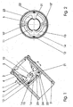
- Fig. 1. and Fig. 2 is a filling nozzle summarily denoted by 1. It consists of a leading to the fuel tank, not shown, tube 2, designed for receiving a closure ring cap 3 and an insert 4.
- the ring cap 3 holds the insert 4 in the tube 2.
- these parts could also be integral.
- An inwardly tapered funnel insert 5 and an inner tube 2 adjacent the tube insert 6 form the insert 4th
- a pivot axis 10 is embodied by two axes 10 ', 10 "arranged between the funnel insert 5 and the tubular insert 6.
- Two elements 11, 21 are pivotable about the axis 10.
- the elements 11, 21 essentially form semicircular arcs opposite directions and are mounted with their ends on the axes 10 ', 10 ".
- the first element 11 has approximately in the middle of the bow an oblique shoulder 13 and a hinge axis 14 about which a flap 16 can be pushed against the force of a torsion spring 15. Furthermore, there attacks a compression spring 12, which tends to push the hinge axis 14 inward and is supported with its other end inside the tube insert 6.
- the second element 21 is here a locking lever, which has approximately in the middle of the sheet an inclined shoulder 23 and a claw 24 which engages around the flap on its hinge axis 14 opposite side and so locked. Also, it is acted upon by a compression spring 22 inwardly.
- Fig. 3 shows the effect of the invention when inserting a filling tube 30 with the correct diameter, which belongs to a nozzle for the correct fuel. This is about the smallest diameter of the hopper insert 5, at least not significantly smaller.
- the filling tube 30 can then simultaneously move both shoulders 13, 23 and with them both elements 11, 21 outwards. This will simultaneously on one side of the Claw 24 pulled away from the flap 16 and on the other side, the hinge axis 14 with the flap 16 of the claw 24 away.
- Fig. 4 shows the effect of the invention in introducing a too small diameter fill tube 30 * associated with a false fuel nozzle.
- the filling tube 30 * in order to outwit the lock, guided so that the first member 11 is pressed with the hinge axis 14 and the flap 16 against the force of the spring 12 to the outside.
- the other compression spring 22 on the opposite side of the second element with the locking claw 24 to move towards the center, so that it keeps the flap 16 still locked.
- the filling tube 30 * is inserted so that it moves the element 21 with the locking claw 24 against the force of its spring 22, so follows the flap 16 in the direction of the locking claw 24 thanks to the first spring 12.
- the embodiment of the Fig. 5 and Fig. 6 differs from the previous one in that the funnel insert 5 is adjoined by a funnel part 107 pivotable about the axis 10 and that both elements 111, 121 are locking claws.
- the pivotable funnel portion 107 carries at its lower edge the hinge axis 114 with torsion spring 115 of the flap 116, wherein the hinge axis 114 here - viewed in the direction of the longitudinal axis of the entire filling nozzle - is aligned at right angles to the pivot axis 110.
Landscapes
- Engineering & Computer Science (AREA)
- Life Sciences & Earth Sciences (AREA)
- Sustainable Development (AREA)
- Sustainable Energy (AREA)
- Chemical & Material Sciences (AREA)
- Combustion & Propulsion (AREA)
- Transportation (AREA)
- Mechanical Engineering (AREA)
- Cooling, Air Intake And Gas Exhaust, And Fuel Tank Arrangements In Propulsion Units (AREA)
Description
- Die Erfindung betrifft Füllstutzen für den Treibstofftank eines Kraftfahrzeuges mit einem Trichtereinsatz und einwärts daran anschließend einer schwenkbaren Klappe mit einem Verriegelungselement, welches von dem Füllrohr einer Zapfpistole gegen die Kraft einer Feder so verschwenkbar ist, dass es die Klappe freigibt. Zum Betanken wird das Füllrohr einer Zapfpistole in den Trichterteil eingeführt, wobei der Durchmesser des Füllrohres je nach Art des Treibstoffes verschieden ist. Für Dieseltreibstoff und verbleites Benzin (das im Aussterben ist) ist er groß, für bleifreies Benzin klein. Entsprechend ist der engste Durchmesser des Trichterteiles gewählt.
- Es ist unmöglich das dickere Füllrohr in den engeren Trichter einzuführen. Wie aber ist ein Einführen des dünneren Endrohres in den weiteren Trichter zu verhindern ? Das ist die der Erfindung zugrunde liegende Frage.
- Aus der
EP 11 99 208 A1 ist eine Lösung dieses Problems bekannt. Sie besteht darin, dass der innere Teil des Trichters etwas enger als das für Dieselkraftstoff weitere Endrohr und in seiner Längsachse verschiebbar ist. Bei Einführen des weiteren Endrohres wird er verschoben und gibt die Verbindung zu einer Betankungsentlüftungsleitung frei, er wirkt gewissermaßen als Ventil. Mit dem engeren Endrohr gelingt das nicht, die Betankungsentlüftung ist blockiert. Damit ist aber das Befüllen mit dem falschen Treibstoff nicht zu verhindern. Bei ausreichend kleinem Durchfluss, wenn nämlich nicht der ganze Querschnitt des Füllrohres flüssigkeitsdurchstömt ist. - Bei einer weiteren aus der
DE 100 51 212 A1 bekannten Vorrichtung wird eine unter der Bezeichnung Bleifreiklappe bekannte Klappe mittels mindestens eines Verriegelungshebels festgehalten, der mit einer Schulter ins innere eines Trichtereinsatzes ragt. Bei Einführen eines Füllrohres mit ausreichend großem Durchmesser wird der Verriegelungshebel beiseite gedrückt und die Klappe geöffnet. Ist der Durchmesser des Füllrohres zu klein, gelingt das nicht. Es hat sich aber gezeigt, dass durch schräges Einführen eines zu dünnen Füllrohres und geeignete Bewegungen der Mechanismus überlistet werden kann. - Ein Füllstutzen mit den Merkmalen des Oberbegriffs des unabhängigen Anspruchs 1 ist bekannt aus
EP-A-1 262 355 . - Die Erfindung soll nun eine Lösung vorschlagen, die das Befüllen mit dem falschen Treibstoff zuverlässig verhindert; natürlich mit geringstmöglichem Bauaufwand.
- Erfindungsgemäß wird das dadurch erreicht, dass die Klappe um eine im Raum verlagerbare Scharnierachse drehbar und von mindestens zwei jeweils um eine Achse schwenkbaren Elementen gehalten ist, die die Klappe nur freigeben, wenn beide Elemente von dem eingeführten Füllrohr gegen die Kraft einer Feder beiseite geschwenkt werden. Dadurch, dass die Scharnierachse nicht raumfest ist, können sich die Klappe und die sie haltenden Elemente im Raum der Schrägstellung des Füllrohres der Zapfpistole entsprechend ausrichten. So ist die Verriegelung nicht mehr zu überlisten. Die Frage, wie die Scharnierachse beweglich geführt ist, kann im Rahmen der Erfindung auf verschiedene Weise gelöst werden. Die Schwenkachsen (oder Schwenkwellen) der Elemente hingegen sind raumfest.
- In einer praktischen Ausführungsform sind zwei vorzugsweise einander gegenüber liegende Elemente um eine gemeinsame Achse schwenkbar, die im Füllstutzen raumfest und über der Klappe angeordnet ist und stützen sich die auf die Elemente wirkenden Federn innen am Füllstutzen ab. Zusammen mit der verlagerbaren Scharnierachse kann so ein Element durch schräges Einführen des Füllrohres eingedrückt werden, das gegenüberliegende wird aber durch seine Feder nachgeführt. Die gemeinsame Achse bringt eine fühlbare Senkung der Herstellungskosten.
- In einer Ausführungsform ist zwischen dem Trichtereinsatz und der Klappe ein um eine raumfeste Achse schwenkbarer Trichterteil, an dem die Scharnierachse für die Klappe angebracht ist und an dessen unterem Rand die geschlossene Klappe anliegt, und ist mindestens eines der schwenkbaren Elemente ein Verriegelungshebel mit einer in den Trichterteil ragenden schrägen Schulter und mit an seinem einwärtigen Ende einer die Klappe umgreifenden Klaue. Die Scharnierachse wird also von dem schwenkbaren Trichterteil geführt, der sich seinerseits nach dem eingeführten Füllrohr der Zapfpistole ausrichtet.
- In Weiterbildung dieser Ausführungsform ist die raumfeste Achse des schwenkbaren Trichterteiles auch die Achse der zwei schwenkbaren Elemente, die einander gegenüberliegende Verriegelungshebel sind und die Scharnierachse quer zu der Schwenkachse der Elemente ist. Es ist also für alle drei beweglichen Teile nur eine einzige Achse erforderlich.
- In einer zweiten, besonders vorteilhaften Ausführungsform trägt eines der schwenkbaren Elemente die Scharnierachse der Klappe und ein weiteres schwenkbares Element ist ein der Scharnierachse gegenüber angeordneter Verriegelungshebel, wobei auf beide schwenkbaren Elemente je eine Druckfeder wirkt, die sich im Inneren des Füllstutzens abstützt. So sind überhaupt nur zwei schwenkbare Elemente erforderlich, wovon eines die Scharnierachse trägt. Hier tritt die überraschende Wirkung der Erfindung besonders stark auf. Wenn nur der Verriegelungshebel gegen die Kraft seiner Feder vom Füllrohr nach aussen gedrückt wird, so wird die ganze Klappe mit ihrer Scharnierachse von ihrer Feder in dieselbe Richtung gedrückt, und bleibt so zuverlässig verriegelt.
- Im folgenden wird die Erfindung anhand von Abbildungen beschrieben und erläutert. Es stellen dar:
- Fig. 1:
- einen Längsschnitt durch den Erfindungsgegenstand in einer ersten Ausfiihrungsform,
- Fig. 2:
- einen Querschnitt 11-M in
Fig. 1 , - Fig. 3:
- einen Längsschnitt zu
Fig. 2 , in richtiger Betankungssituation, - Fig. 4:
- wie
Fig 3 , in falscher Betankungssituation, - Fig. 5:
- einen Längsschnitt durch den Erfindungsgegenstand in einer zweiten Ausführungsform.
- Fig. 6:
- einen Längsschnitt nach VI-VI in
Fig. 5 . - In
Fig. 1. und Fig. 2 ist ein Füllstutzen summarisch mit 1 bezeichnet. Er besteht aus einem zum nicht dargestellten Kraftstoffbehälter führenden Rohr 2, einer für die Aufnahme eines Verschlusses ausgebildete Ringkappe 3 und einem Einsatzstück 4. In der abgebildeten Ausführungsform hält die Ringkappe 3 das Einsatzstück 4 im Rohr 2. Diese Teile könnten aber auch einstückig sein. Ein einwärts konisch zulaufender Trichtereinsatz 5 und ein innen am Rohr 2 anliegender Rohreinsatz 6 bilden das Einsatzstück 4. - In dem Einsatzstück 4 ist eine Schwenkachse 10 durch zwei Achsen 10', 10" verkörpert, die zwischen Trichtereinsatz 5 und Rohreinsatz 6 angeordnet sind. Zwei Elemente 11, 21 sind um die Achse 10 schwenkbar. Die Elemente 11,21 bilden im Wesentlichen Halbkreisbögen in entgegengesetzten Richtungen und sind mit ihren Enden auf den Achsen 10', 10" gelagert. Das erste Element 11 hat ungefähr in Bogenmitte eine schräge Schulter 13 und eine Scharnierachse 14, um die eine Klappe 16 gegen die Kraft einer Drehfeder 15 aufgestoßen werden kann. Weiters greift dort eine Druckfeder 12 an, die die Scharnierachse 14 einwärts zu drücken bestrebt ist und sich mit ihrem anderen Ende innen am Rohreinsatz 6 abstützt. Das zweite Element 21 ist hier ein Verriegelungshebel, der ungefähr in Bogenmitte eine schräge Schulter 23 und eine Klaue 24 hat, die die Klappe an ihrem der Scharnierachse 14 gegenüberliegenden Seite umgreift und so verriegelt. Auch sie wird von eine Druckfeder 22 einwärts beaufschlagt.
-
Fig. 3 zeigt die Wirkung der Erfindung bei Einführen eines Füllrohres 30 mit dem richtigen Durchmesser, das zu einer Zapfpistole für den richtigen Treibstoff gehört. Dieser ist ungefähr der kleinste Durchmesser des Trichtereinsatzes 5, jedenfalls nicht wesentlich kleiner. Das Füllrohr 30 kann dann beide Schultern 13,23 und mit ihnen beide Elemente 11,21 gleichzeitig nach aussen bewegen. Dadurch wird gleichzeitig auf einer Seite die Klaue 24 von der Klappe 16 weggezogen und auf der anderen Seite die Scharnierachse 14 mit der Klappe 16 von der Klaue 24 weg. -
Fig. 4 zeigt die Wirkung der Erfindung bei Einführen eines Füllrohres 30* mit zu kleinem Durchmesser, das zu einer Zapfpistole für den falschen Treibstoff gehört. Das Füllrohr 30* wird, um die Verriegelung zu überlisten, so geführt, dass das erste Element 11 mit der Scharnierachse 14 und der Klappe 16 gegen die Kraft der Feder 12 nach aussen gedrückt wird. Dadurch aber kann die andere Druckfeder 22 auf der gegenüberliegenden Seite das zweite Element mit der Verriegelungsklaue 24 zur Mitte hin verschieben, sodass sie die Klappe 16 weiterhin fest verriegelt hält. Wenn das Füllrohr 30* so eingeführt wird, dass es das Element 21 mit der Verriegelungsklaue 24 gegen die Kraft seiner Feder 22 verschiebt, so folgt dank der ersten Feder 12 die Klappe 16 in Richtung zur Verriegelungsklaue 24. - Die Ausführungsform der
Fig. 5 und Fig. 6 , in der entsprechende Bezugszeichen um 100 erhöht sind, unterscheidet sich von der vorhergehenden dadurch, dass an den Trichtereinsatz 5 ein um die Achse 10 schwenkbarer Trichterteil 107 anschließt und dass beide Elemente 111, 121 Verriegelungsklauen sind. Der schwenkbare Trichterteil 107 trägt an seinem unteren Rand die Scharnierachse 114 mit Drehfeder 115 der Klappe 116, wobei die Scharnierachse 114 hier - in Richtung der Längsachse des ganzen Füllstutzens gesehen - rechtwinkelig zur Schwenkachse 110 ausgerichtet ist.
Claims (5)
- Füllstutzen (1) für den Treibstofftank eines Kraftfahrzeuges mit einem Trichtereinsatz (5) und einwärts daran anschließend einer Klappe (16) mit einem Verriegelungselement (24), welches beim Einführen des Füllrohres einer Zapfpistole so bewegt wird, dass es die Klappel (16) freigibt, dadurch gekennzeichnet dass die Klappe (16; 116) um eine im Raum verlagerbare Scharnierachse (14; 114) drehbar und von mindestens zwei jeweils um eine Achse (10; 110) schwenkbaren Elementen (11,21;111,121) gehalten ist, die die Klappe (16; 116) nur freigeben, wenn beide Elemente (11,21; 111, 121) von dem eingeführten Füllrohr (30) gegen die Kraft einer Feder (12, 22; 112,122) beiseite geschwenkt werden.
- Füllstutzen nach Anspruch 1, dadurch gekennzeichnet, dass zwei Elemente (11,21; 111,121) um eine gemeinsame Achse (10; 110) schwenkbar sind, die im Füllstutzen (1;101) raumfest über der Klappe (16; 116) angeordnet ist und dass die auf die Elemente (11,21; 111,121) wirkenden Federn (12,22; 112,122) sich innen am Füllstutzen (1:101) abstützen.
- Füllstutzen nach Anspruch 1, dadurch gekennzeichnet, dass zwischen dem Trichtereinsatz (105) und der Klappe (116) ein um eine raumfeste Achse (110) schwenkbarer Trichterteil (107) ist, an dem die Scharnierachse (114) für die Klappe (116) angebracht ist und an dessen unterem Rand die geschlossene Klappe (116) anliegt, und dass mindestens ein schwenkbares Element (111,121) ein Verriegelungshebel mit einer in den Trichterteil (107) ragenden Schulter (13) und mit einer einwärts der Schulter (123) die Klappe (116) umgreifenden Klaue (124) ist.
- Füllstutzen nach Anspruch 3, dadurch gekennzeichnet, dass die raumfeste Achse (110) des schwenkbaren Trichterteiles (107) auch die Achse (110) der zwei schwenkbaren Elemente (111,121) ist, die einander gegenüberliegende Verriegelungshebel sind und die Scharnierachse (114) quer zu der Schwenkachse (110) der Elemente ist.
- Füllstutzen nach Anspruch 1, dadurch gekennzeichnet, dass eines (11) der schwenkbaren Elemente (11,21) die Scharnierachse (14) der Klappe (16) trägt und ein weiteres schwenkbares Element (21) ein der Scharnierachse (14) gegenüber angeordneter Verriegelungshebel ist, und dass auf beide schwenkbaren Elemente (11,21) je eine Druckfeder (12,22) wirkt, die sich im Inneren des Füllstutzens (1) abstützt.
Priority Applications (1)
| Application Number | Priority Date | Filing Date | Title |
|---|---|---|---|
| AT05762977T ATE409610T1 (de) | 2004-07-16 | 2005-07-15 | Füllrohr für den treibstofftank eines kraftfahrzeuges mit selektiver öffnung |
Applications Claiming Priority (2)
| Application Number | Priority Date | Filing Date | Title |
|---|---|---|---|
| AT0050404U AT7933U1 (de) | 2004-07-16 | 2004-07-16 | Füllrohr für den treibstofftank eines kraftfahrzeuges mit selektiver öffnung |
| PCT/AT2005/000276 WO2006007618A1 (de) | 2004-07-16 | 2005-07-15 | Füllrohr für den treibstofftank eines kraftfahrzeuges mit selektiver öffnung |
Publications (2)
| Publication Number | Publication Date |
|---|---|
| EP1778512A1 EP1778512A1 (de) | 2007-05-02 |
| EP1778512B1 true EP1778512B1 (de) | 2008-10-01 |
Family
ID=34916760
Family Applications (1)
| Application Number | Title | Priority Date | Filing Date |
|---|---|---|---|
| EP05762977A Expired - Lifetime EP1778512B1 (de) | 2004-07-16 | 2005-07-15 | Füllrohr für den treibstofftank eines kraftfahrzeuges mit selektiver öffnung |
Country Status (6)
| Country | Link |
|---|---|
| US (1) | US7621303B2 (de) |
| EP (1) | EP1778512B1 (de) |
| AT (2) | AT7933U1 (de) |
| CA (1) | CA2576356C (de) |
| DE (1) | DE502005005558D1 (de) |
| WO (1) | WO2006007618A1 (de) |
Families Citing this family (35)
| Publication number | Priority date | Publication date | Assignee | Title |
|---|---|---|---|---|
| DE202005012256U1 (de) * | 2005-07-27 | 2006-12-14 | Reutter Metallwarenfabrik Gmbh | Fehlbetankungsvorrichtung |
| GB2431634A (en) * | 2005-10-25 | 2007-05-02 | Rhys Holdaway | Device to prevent incorrect fuelling of a vehicle |
| CZ16520U1 (cs) * | 2006-02-21 | 2006-05-22 | Epp Praha, S. R. O. | Plnicí hrdlo nádrze automobilu s dieselovým motorem |
| KR20080106577A (ko) * | 2006-03-15 | 2008-12-08 | 이너지 오토모티브 시스템즈 리서치 (소시에떼 아노님) | 연료 분사 노즐 억제자 |
| DE102006014438B4 (de) * | 2006-03-27 | 2009-12-24 | Alfmeier Präzision AG Baugruppen und Systemlösungen | Tankeinfüllstutzen für Diesel-Kraftfahrzeuge |
| US20080178962A1 (en) * | 2007-01-22 | 2008-07-31 | Inergy Auto. Systems Research (Societe Anonyme) | Sealing system for fill pipe head and associated pipe |
| AT9945U1 (de) * | 2007-03-27 | 2008-06-15 | Magna Steyr Fuel Systems Gesmb | Einfüllstutzen eines treibstofftanks mit schutz vor fehlbetankung |
| EP2134562B1 (de) * | 2007-04-16 | 2015-09-16 | Illinois Tool Works Inc. | Selektives kraftstoffdüsenhemmsystem |
| WO2009013558A1 (en) * | 2007-07-23 | 2009-01-29 | Renault Trucks | Arrangement of a filler neck for a vehicle tank |
| JP4778943B2 (ja) * | 2007-10-12 | 2011-09-21 | 本田技研工業株式会社 | 車両の給油口装置 |
| IL186686A0 (en) * | 2007-10-16 | 2008-02-09 | Av Doron | Normally-closed opening closure |
| DE102008049150A1 (de) * | 2008-06-09 | 2009-12-10 | Kt Projektentwicklungs-Gmbh | Einsatzelement für einen zur tankstellenseitigen Befüllung mit Harnstoff geeigneten Behälter |
| US8763656B2 (en) * | 2008-08-25 | 2014-07-01 | Nifco Inc. | Device for preventing fueling error |
| DE102009009998A1 (de) * | 2009-02-23 | 2010-08-26 | Kt Projektentwicklungs Gmbh | Sicherheitselement für einen Diesel-Kraftstoffbehälter zur Unterbindung einer Fehlbetankung |
| US20100218849A1 (en) * | 2009-02-27 | 2010-09-02 | Toyoda Gosei Co., Ltd. | Fuel tank opening-closing device |
| GB2470351A (en) * | 2009-05-14 | 2010-11-24 | Robert Colin Mason | Fuel filling device which prevents misfuelling |
| WO2011062193A1 (ja) * | 2009-11-18 | 2011-05-26 | 株式会社ニフコ | 誤給油防止装置 |
| CN102343806A (zh) * | 2010-08-02 | 2012-02-08 | 北汽福田汽车股份有限公司 | 燃油加注筒和具有该燃油加注筒的燃油箱 |
| JP5406158B2 (ja) * | 2010-10-14 | 2014-02-05 | 豊田合成株式会社 | 燃料タンクの開閉装置 |
| DE102011011518B4 (de) | 2011-02-17 | 2012-11-29 | Magna Steyr Fuel Systems Gesmbh | Füllstutzen für den Treibstofftank eines Kraftfahrzeuges mit selektiver Öffnung |
| US9133013B2 (en) | 2011-06-03 | 2015-09-15 | Curtis Roys | Method and structure for prevention of incorrect fueling operations |
| US8678049B2 (en) | 2011-06-03 | 2014-03-25 | Curtis Roys | Method and structure for prevention of incorrect fueling operations for diesel-powered vehicles |
| US10000117B2 (en) | 2012-02-17 | 2018-06-19 | Stant Usa Corp. | Filler neck closure assembly |
| US9457650B2 (en) * | 2012-08-28 | 2016-10-04 | Ford Global Technologies, Llc | Drain slot for capless fuel filler insert |
| KR101417637B1 (ko) * | 2013-05-08 | 2014-07-08 | 현대자동차주식회사 | 혼유 방지 필러넥 장치 |
| US9701194B2 (en) | 2013-05-10 | 2017-07-11 | Stant Usa Corp. | Fuel-dispensing nozzle inhibitor |
| KR101481272B1 (ko) * | 2013-05-28 | 2015-01-09 | 현대자동차주식회사 | 혼유 방지 필러넥 장치 |
| RU2651441C1 (ru) * | 2013-11-29 | 2018-04-19 | Вольво Трак Корпорейшн | Узел заливной горловины и снабженный им бак |
| US9266428B2 (en) | 2014-04-15 | 2016-02-23 | Honda Motor Co., Ltd. | Capless fuel filler assembly for vehicle |
| KR101510051B1 (ko) | 2014-04-16 | 2015-04-07 | 현대자동차주식회사 | 차량의 혼유 방지 시스템 |
| US10081241B2 (en) | 2015-12-10 | 2018-09-25 | Curtis Alan Roys | Diesel fuel guard |
| US9987922B2 (en) * | 2016-08-16 | 2018-06-05 | Ford Global Technologies, Llc | Capless refueling mechanism |
| JP7131530B2 (ja) * | 2019-11-13 | 2022-09-06 | 豊田合成株式会社 | 給油装置 |
| JP7192746B2 (ja) * | 2019-11-13 | 2022-12-20 | 豊田合成株式会社 | 給油装置 |
| JP7131529B2 (ja) * | 2019-11-13 | 2022-09-06 | 豊田合成株式会社 | 給油装置 |
Family Cites Families (8)
| Publication number | Priority date | Publication date | Assignee | Title |
|---|---|---|---|---|
| US3730216A (en) * | 1972-04-06 | 1973-05-01 | Ford Motor Co | Fuel tank insert for admitting preselected pump nozzles |
| DE10051212B4 (de) | 2000-10-16 | 2018-02-08 | Volkswagen Ag | Tankeinfüllstutzen mit Sperrvorrichtung |
| DE10051847A1 (de) | 2000-10-19 | 2002-08-29 | Bayerische Motoren Werke Ag | Kraftfahrzeug-Kraftstofftank mit einem Einfüllstutzen zur Aufnahme einer Zapfpistole für Dieselkraftstoff |
| DE10126207A1 (de) | 2001-05-30 | 2003-01-16 | Bayerische Motoren Werke Ag | Kraftfahrzeug-Kraftstofftank mit einem Einfüllstutzen zur Aufnahme einer Zapfpistole für Dieselkraftstoff |
| DE10157090C1 (de) * | 2001-11-21 | 2003-04-24 | Arno Goettsche | Anordnung zum Verhindern des Betankens eines Dieselfahrzeuges mit bleifreiem Benzin |
| US7077178B2 (en) * | 2004-08-11 | 2006-07-18 | Stant Manufacturing Inc. | Fuel-dispensing nozzle inhibitor |
| US6968874B1 (en) * | 2004-10-07 | 2005-11-29 | Martinrea Industries, Inc. | Capless automotive fueling system |
| US7293586B2 (en) * | 2005-06-22 | 2007-11-13 | Stant Manufacturing Inc. | Fuel-dispensing nozzle inhibitor |
-
2004
- 2004-07-16 AT AT0050404U patent/AT7933U1/de not_active IP Right Cessation
-
2005
- 2005-07-15 DE DE502005005558T patent/DE502005005558D1/de not_active Expired - Lifetime
- 2005-07-15 US US11/632,506 patent/US7621303B2/en not_active Expired - Lifetime
- 2005-07-15 EP EP05762977A patent/EP1778512B1/de not_active Expired - Lifetime
- 2005-07-15 WO PCT/AT2005/000276 patent/WO2006007618A1/de not_active Ceased
- 2005-07-15 AT AT05762977T patent/ATE409610T1/de active
- 2005-07-15 CA CA2576356A patent/CA2576356C/en not_active Expired - Lifetime
Also Published As
| Publication number | Publication date |
|---|---|
| US20080092986A1 (en) | 2008-04-24 |
| CA2576356C (en) | 2013-04-16 |
| AT7933U1 (de) | 2005-11-15 |
| WO2006007618A1 (de) | 2006-01-26 |
| US7621303B2 (en) | 2009-11-24 |
| DE502005005558D1 (de) | 2008-11-13 |
| EP1778512A1 (de) | 2007-05-02 |
| ATE409610T1 (de) | 2008-10-15 |
| CA2576356A1 (en) | 2006-01-26 |
Similar Documents
| Publication | Publication Date | Title |
|---|---|---|
| EP1778512B1 (de) | Füllrohr für den treibstofftank eines kraftfahrzeuges mit selektiver öffnung | |
| EP1974976B1 (de) | Einfüllstutzen eines Treibstofftanks mit Schutz vor Fehlbetankung | |
| DE102004002994B3 (de) | Einfüllstutzen für das Einfüllen von Kraftstoff in einen Fahrzeugtank | |
| DE10157090C1 (de) | Anordnung zum Verhindern des Betankens eines Dieselfahrzeuges mit bleifreiem Benzin | |
| EP1319545B2 (de) | Vorrichtung zur Betankung von Dieselfahrzeugen | |
| EP1262355B1 (de) | Kraftfahrzeug-Kraftstofftank mit einem Einfüllstutzen zur Aufnahme einer Zapfpistole für Dieselkraftstoff | |
| EP1284212B1 (de) | Kraftfahrzeug-Kraftstofftank mit einem Einfüllstutzen zur Aufnahme einer Zapfpistole für Dieselkraftstoff | |
| EP0602440B1 (de) | Verschluss zum Verschliessen der Mündung eines Stutzens | |
| EP2489538B1 (de) | Füllstutzen für den Treibstofftank eines Kraftfahrzeuges mit selektiver Öffnung | |
| DE3117935A1 (de) | "sicherheitsverbindungsschieber" | |
| DE10051212B4 (de) | Tankeinfüllstutzen mit Sperrvorrichtung | |
| DE4237790C2 (de) | Selbstschließender Behälterverschluß | |
| DE3742258C1 (de) | Kraftstoffbehaelter | |
| DE29914746U1 (de) | Klappscharnier-Gelenk | |
| DE19919251A1 (de) | Verschlußeinrichtung für einen Kraftstoffbehälter eines Kraftfahrzeuges | |
| DE202004013627U1 (de) | Einfüllstutzen für einen Kraftfahrzeug-Kraftstofftank | |
| DE102020124298A1 (de) | Deckellose einfüllstutzenstruktur | |
| DE19812384A1 (de) | Kraftstoffbehälterverschluß | |
| DE102006026282A1 (de) | Drehfallenverschluss für eine Frontklappe mit Fußgängerschutz | |
| EP1056612A1 (de) | Selbsttätig schliessender tankdeckel | |
| DE102015106014A1 (de) | Gelenkanordnung einer Dachkappe eines Verdecks eines Kraftfahrzeugs | |
| DE102012022394A1 (de) | Kraftstoffeinfülleinrichtung | |
| CH648243A5 (de) | Klappe an einem fahrzeug, insbesondere einem omnibus. | |
| DE102008036071B4 (de) | Tankstutzen mit Sperreinrichtung für dessen Verschlussklappe | |
| DE29921802U1 (de) | Scharnierfeder für eine Tankklappe eines Kraftfahrzeugs |
Legal Events
| Date | Code | Title | Description |
|---|---|---|---|
| PUAI | Public reference made under article 153(3) epc to a published international application that has entered the european phase |
Free format text: ORIGINAL CODE: 0009012 |
|
| 17P | Request for examination filed |
Effective date: 20070216 |
|
| AK | Designated contracting states |
Kind code of ref document: A1 Designated state(s): AT DE FR GB |
|
| DAX | Request for extension of the european patent (deleted) | ||
| RBV | Designated contracting states (corrected) |
Designated state(s): AT DE FR GB |
|
| GRAP | Despatch of communication of intention to grant a patent |
Free format text: ORIGINAL CODE: EPIDOSNIGR1 |
|
| GRAS | Grant fee paid |
Free format text: ORIGINAL CODE: EPIDOSNIGR3 |
|
| GRAA | (expected) grant |
Free format text: ORIGINAL CODE: 0009210 |
|
| RAP1 | Party data changed (applicant data changed or rights of an application transferred) |
Owner name: MAGNA STEYR FUEL SYSTEMS GESMBH |
|
| AK | Designated contracting states |
Kind code of ref document: B1 Designated state(s): AT DE FR GB |
|
| REG | Reference to a national code |
Ref country code: GB Ref legal event code: FG4D Free format text: NOT ENGLISH |
|
| REF | Corresponds to: |
Ref document number: 502005005558 Country of ref document: DE Date of ref document: 20081113 Kind code of ref document: P |
|
| PLBE | No opposition filed within time limit |
Free format text: ORIGINAL CODE: 0009261 |
|
| STAA | Information on the status of an ep patent application or granted ep patent |
Free format text: STATUS: NO OPPOSITION FILED WITHIN TIME LIMIT |
|
| 26N | No opposition filed |
Effective date: 20090702 |
|
| REG | Reference to a national code |
Ref country code: FR Ref legal event code: PLFP Year of fee payment: 11 |
|
| REG | Reference to a national code |
Ref country code: FR Ref legal event code: PLFP Year of fee payment: 12 |
|
| REG | Reference to a national code |
Ref country code: FR Ref legal event code: PLFP Year of fee payment: 13 |
|
| REG | Reference to a national code |
Ref country code: FR Ref legal event code: PLFP Year of fee payment: 14 |
|
| REG | Reference to a national code |
Ref country code: DE Ref legal event code: R082 Ref document number: 502005005558 Country of ref document: DE Representative=s name: RAUSCH, GABRIELE, DIPL.-PHYS. DR.RER.NAT., DE Ref country code: DE Ref legal event code: R081 Ref document number: 502005005558 Country of ref document: DE Owner name: MAGNA ENERGY STORAGE SYSTEMS GESMBH, AT Free format text: FORMER OWNER: MAGNA STEYR FUEL SYSTEMS GESMBH, SINABELKIRCHEN, AT |
|
| PGFP | Annual fee paid to national office [announced via postgrant information from national office to epo] |
Ref country code: GB Payment date: 20220720 Year of fee payment: 18 Ref country code: DE Payment date: 20220720 Year of fee payment: 18 Ref country code: AT Payment date: 20220721 Year of fee payment: 18 |
|
| PGFP | Annual fee paid to national office [announced via postgrant information from national office to epo] |
Ref country code: FR Payment date: 20220720 Year of fee payment: 18 |
|
| REG | Reference to a national code |
Ref country code: DE Ref legal event code: R119 Ref document number: 502005005558 Country of ref document: DE |
|
| REG | Reference to a national code |
Ref country code: AT Ref legal event code: MM01 Ref document number: 409610 Country of ref document: AT Kind code of ref document: T Effective date: 20230715 |
|
| GBPC | Gb: european patent ceased through non-payment of renewal fee |
Effective date: 20230715 |
|
| PG25 | Lapsed in a contracting state [announced via postgrant information from national office to epo] |
Ref country code: AT Free format text: LAPSE BECAUSE OF NON-PAYMENT OF DUE FEES Effective date: 20230715 |
|
| PG25 | Lapsed in a contracting state [announced via postgrant information from national office to epo] |
Ref country code: DE Free format text: LAPSE BECAUSE OF NON-PAYMENT OF DUE FEES Effective date: 20240201 Ref country code: AT Free format text: LAPSE BECAUSE OF NON-PAYMENT OF DUE FEES Effective date: 20230715 Ref country code: GB Free format text: LAPSE BECAUSE OF NON-PAYMENT OF DUE FEES Effective date: 20230715 |
|
| PG25 | Lapsed in a contracting state [announced via postgrant information from national office to epo] |
Ref country code: FR Free format text: LAPSE BECAUSE OF NON-PAYMENT OF DUE FEES Effective date: 20230731 |