EP1778859B1 - Détection de microorganismes au moyen d'un dispositif de détection par fluorescence - Google Patents
Détection de microorganismes au moyen d'un dispositif de détection par fluorescence Download PDFInfo
- Publication number
- EP1778859B1 EP1778859B1 EP05776767.5A EP05776767A EP1778859B1 EP 1778859 B1 EP1778859 B1 EP 1778859B1 EP 05776767 A EP05776767 A EP 05776767A EP 1778859 B1 EP1778859 B1 EP 1778859B1
- Authority
- EP
- European Patent Office
- Prior art keywords
- visible
- semi
- light
- fluid barrier
- container
- Prior art date
- Legal status (The legal status is an assumption and is not a legal conclusion. Google has not performed a legal analysis and makes no representation as to the accuracy of the status listed.)
- Expired - Lifetime
Links
Images
Classifications
-
- G—PHYSICS
- G01—MEASURING; TESTING
- G01N—INVESTIGATING OR ANALYSING MATERIALS BY DETERMINING THEIR CHEMICAL OR PHYSICAL PROPERTIES
- G01N21/00—Investigating or analysing materials by the use of optical means, i.e. using sub-millimetre waves, infrared, visible or ultraviolet light
- G01N21/62—Systems in which the material investigated is excited whereby it emits light or causes a change in wavelength of the incident light
- G01N21/63—Systems in which the material investigated is excited whereby it emits light or causes a change in wavelength of the incident light optically excited
- G01N21/64—Fluorescence; Phosphorescence
- G01N21/6486—Measuring fluorescence of biological material, e.g. DNA, RNA, cells
-
- C—CHEMISTRY; METALLURGY
- C12—BIOCHEMISTRY; BEER; SPIRITS; WINE; VINEGAR; MICROBIOLOGY; ENZYMOLOGY; MUTATION OR GENETIC ENGINEERING
- C12Q—MEASURING OR TESTING PROCESSES INVOLVING ENZYMES, NUCLEIC ACIDS OR MICROORGANISMS; COMPOSITIONS OR TEST PAPERS THEREFOR; PROCESSES OF PREPARING SUCH COMPOSITIONS; CONDITION-RESPONSIVE CONTROL IN MICROBIOLOGICAL OR ENZYMOLOGICAL PROCESSES
- C12Q1/00—Measuring or testing processes involving enzymes, nucleic acids or microorganisms; Compositions therefor; Processes of preparing such compositions
- C12Q1/02—Measuring or testing processes involving enzymes, nucleic acids or microorganisms; Compositions therefor; Processes of preparing such compositions involving viable microorganisms
- C12Q1/04—Determining presence or kind of microorganism; Use of selective media for testing antibiotics or bacteriocides; Compositions containing a chemical indicator therefor
-
- C—CHEMISTRY; METALLURGY
- C12—BIOCHEMISTRY; BEER; SPIRITS; WINE; VINEGAR; MICROBIOLOGY; ENZYMOLOGY; MUTATION OR GENETIC ENGINEERING
- C12Q—MEASURING OR TESTING PROCESSES INVOLVING ENZYMES, NUCLEIC ACIDS OR MICROORGANISMS; COMPOSITIONS OR TEST PAPERS THEREFOR; PROCESSES OF PREPARING SUCH COMPOSITIONS; CONDITION-RESPONSIVE CONTROL IN MICROBIOLOGICAL OR ENZYMOLOGICAL PROCESSES
- C12Q1/00—Measuring or testing processes involving enzymes, nucleic acids or microorganisms; Compositions therefor; Processes of preparing such compositions
- C12Q1/02—Measuring or testing processes involving enzymes, nucleic acids or microorganisms; Compositions therefor; Processes of preparing such compositions involving viable microorganisms
- C12Q1/04—Determining presence or kind of microorganism; Use of selective media for testing antibiotics or bacteriocides; Compositions containing a chemical indicator therefor
- C12Q1/06—Quantitative determination
-
- G—PHYSICS
- G01—MEASURING; TESTING
- G01N—INVESTIGATING OR ANALYSING MATERIALS BY DETERMINING THEIR CHEMICAL OR PHYSICAL PROPERTIES
- G01N21/00—Investigating or analysing materials by the use of optical means, i.e. using sub-millimetre waves, infrared, visible or ultraviolet light
- G01N21/62—Systems in which the material investigated is excited whereby it emits light or causes a change in wavelength of the incident light
- G01N21/63—Systems in which the material investigated is excited whereby it emits light or causes a change in wavelength of the incident light optically excited
- G01N21/64—Fluorescence; Phosphorescence
- G01N21/6428—Measuring fluorescence of fluorescent products of reactions or of fluorochrome labelled reactive substances, e.g. measuring quenching effects, using measuring "optrodes"
-
- G—PHYSICS
- G01—MEASURING; TESTING
- G01N—INVESTIGATING OR ANALYSING MATERIALS BY DETERMINING THEIR CHEMICAL OR PHYSICAL PROPERTIES
- G01N33/00—Investigating or analysing materials by specific methods not covered by groups G01N1/00 - G01N31/00
- G01N33/48—Biological material, e.g. blood, urine; Haemocytometers
- G01N33/50—Chemical analysis of biological material, e.g. blood, urine; Testing involving biospecific ligand binding methods; Immunological testing
- G01N33/58—Chemical analysis of biological material, e.g. blood, urine; Testing involving biospecific ligand binding methods; Immunological testing involving labelled substances
- G01N33/582—Chemical analysis of biological material, e.g. blood, urine; Testing involving biospecific ligand binding methods; Immunological testing involving labelled substances with fluorescent label
Definitions
- the present invention relates to fluorescence-based devices for detecting microbial growth from test samples.
- One area of biological testing of food, dairy, pharmaceutical, cosmetic and related types of products involves the estimation of total numbers of bacteria, yeasts and molds, as well as concentrations of specific groups of organisms within the material.
- One widely used method is known as the "Standard Plate Count” method and involves culturing a diluted sample of the product in an agar growth medium. The plates containing the sample and the growth medium are incubated (e.g., 32°C - 40°C) for 24 hours to 5 days, depending upon the assay. After incubation, colonies of microorganisms which have grown in the agar are counted.
- Optical methods have been successfully used to classify microorganisms in clinical samples (e.g., PASCO by Difco, Detroit, Michigan).
- the solid substances of the test samples disposed in an aqueous media usually cause optical interference for a detection system. More specifically, when solid substances are disposed in a media to allow for culturing microorganisms, the colorimetric detection system must pass light either through or reflect light from the media containing the solid substance. In most of the cases, the solid substances interfere with the spectral characteristics of the media, yielding a poor signal-to-noise ratio of the detection system.
- a device for continuously monitoring the biological activity in a specimen is described by Eden in U.S. Pat. No. 5,366,873 . It describes a device and method for detecting microbial growth from a sample substance.
- the device includes a container which is at least partially transparent and fluid disposed in the container for cultivating microorganisms therein.
- An indicator substance is disposed in the fluid layer for undergoing transformation in the presence of microorganism growth.
- a second layer, composed of semi fluid substance, indicators and other substances, such as growth media, is disposed in the container.
- the substances within the semi-fluid phase are in equilibrium with the substances in the fluid layer and provide a barrier to solid substances introduced into the fluid layer while providing a zone within which changes in the indicator substance, due to microbial growth, can be detected.
- the indicator substance has been dyes that are affected by the PH variations in the fluid layer.
- Document DE 100 38 080 A1 relates to a method of registering the presence of immobilized substances on a bio-chip carrier by using a fluorescence scanner, wherein a pulse laser excites fluorescent markings to be detected between the pulses.
- the apparatus may comprise a photodiode as a sensor.
- Document WO 01/28006 relates to a high-performance ultraviolet excitation source made of one or more ultraviolet-emitting LED's.
- Such an ultraviolet-emitting source may be used for authenticating both visible (watermarks) and invisible (ultraviolet fluorescent) features of an article under examination, wherein the source further comprises at least one white-light LED.
- the present invention provides a method for detecting microbial growth using the detection of visible-band fluorescence signals generated by at least one fluorescing compound excited by ultraviolet energy according to independent claims 1 and 18.
- the present invention further provides a device for detecting microbial growth by detecting visible-band fluorescence signals generated by at least one fluorescing compound excited by ultraviolet energy according to independent claim 19 and a device for detecting microbial growth by detecting visible-band fluorescence signals and visible-band secondary signals generated by at least one fluorescing compound excited by ultraviolet and visible-band energy according to independent claim 38.
- Preferred embodiments are defined in the dependent claims.
- the present invention provides a device for detecting microbial growth from a sample substance wherein the device includes at least one container which is at least partially transparent to visual and/or ultraviolet (UV) radiation.
- a fluid layer can be disposed in the container for cultivating microorganisms therein.
- a fluorescing indicator substance can be disposed in the fluid layer for undergoing transformation in the presence of microorganism growth.
- a barrier layer can be disposed in the container which is a semi-fluid substance, the fluid portion of which is the same composition as the fluid layer in which the microorganisms are cultivated. Therefore, the fluid in the semi-fluid layer is in equilibrium with the fluid layer.
- the semi-fluid substance provides a barrier to solid substances introduced into the fluid layer while providing a zone within which changes in the at least one fluorescing indicator substance, due to microbial growth, can be detected.
- the barrier layer can be comprised of gelling agents, such as agar.
- gelling agents such as agar.
- any type of gelling substance or agar, as defined in the Merck Index can be utilized.
- gelling products There are several commercial gelling products available which are suitable, including gelatin, carrageenan and pectin.
- the important property of such gelling agents used in the present invention is their ability to transfer ions, such as H+ and small molecules, while blocking out bacteria and larger debris particles. If the concentration of the small particles changes due to organism growth (e.g., pH or Redox reactions), the concentration of the identical particles in the barrier layer will track those changes as well. The diffusion coefficient of the barrier layer determines the rate in which variations in the liquid layer are tracked by identical changes in the barrier layer.
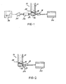
- FIG. 1 illustrates a typical configuration of the various components of a system which can be utilized in accordance with this invention.
- the vial 10 is made of UV-transparent material (e.g., glass, UV-transparent plastics).
- the barrier layer 16 may be composed of any available agar (e.g., Muller Hinton Agar by Difco, Detroit, Michigan) and non-toxic fluorescing dye 14, such as Umbelliferon. This layer can be manufactured by dispensing the mixture, thermally sterilized, to the bottom of the vial 10 and letting it solidify at room temperature. A sterile mixture of the liquid media 12 and dye 14 is poured at room temperature on top of the barrier layer.
- the test sample 28 is placed in the fluid layer.
- the vial 10 is then placed in an incubating device, at an appropriate temperature, to promote growth of organisms.
- the incubating device can be an air incubator, heating and cooling blocks or heat exchanger.
- An ultraviolet light source 18 is positioned at the bottom part of the vial 10 such that the transmitted UV light is directed through the UV-transparent walls of the vial 10 and the barrier layer 16.
- the light source can comprise any long or short wave ultraviolet from various UV sources. For example, greater than 50% of the wavelengths from the light source can be below 400 nanometers. In certain embodiments, at least 75% of the wavelengths from the light source can be below 400 nanometers, for example, at least 85% of the wavelengths from the light source can be below 400 nanometers, and at least 95% of the wavelengths from the light source can be below 400 nanometers.
- LED Light emitting diodes
- greater than 50% of the light generated by the light emitting diode can have a wavelength below 400 nanometers, such as, for example, greater than 75%, greater than 85%, and greater than 95%.
- a long wavelength ultraviolet Light Emitting Diode e.g., 350 to 400 nanometers
- a long wavelength ultraviolet Light Emitting Diode e.g., 350 to 400 nanometers
- a multiplicity of light emitting diodes can be controlled by the controller 20, which provides electrical energy which can be spatially uniform and stable.
- Suitable materials that can be used as the at least one fluorescing compound include materials that emit visible light upon exposure to ultraviolet radiation, such as, for example, umbelliferons and coumarins.
- ultraviolet radiation such as, for example, umbelliferons and coumarins.
- the wavelength of the radiation emitted from the fluorescing compound is longer than that of the light source. For example, radiating umbelliferon with a UV light source of 380 nanometers (invisible) generates a blue-green visible radiation. Consequently, care should be taken that the light sensor will not be influenced by stray light generated by the UV light source. If the UV source 18 is placed directly facing the light sensor 22, as shown in FIG. 1 , an additional band pass optical filter 23 is required to block the influence of the UV radiation on the sensor.
- the UV light source 18 and the sensor 22 can be placed next to each other facing the UV-transparent section of the vial at specific angles, as shown in FIG. 2 , so that the fluorescing radiation is reflected back to the light sensor. Since the fluorescing radiation is equally radiated in all directions, the specific angles can be set to minimize UV reflected light, thereby allowing the light sensor to measure only the fluorescing energy.
- the dynamic changes of the fluorescing light which is the indicator of bacterial activity, is converted to electrical energy utilizing a light sensor 22.
- sensors e.g., photo voltaics, photodiodes, phototransistors, photo multipliers, charged coupled devices (CCD) and multi-channel devices
- CCD charged coupled devices
- low-cost solid state sensors can be employed due to the high energy of light reaching the sensor. Therefore, each vial can have its own pair of light source and sensor, thus eliminating complex mechanical indexing devices utilized in optical readers and thereby increasing the reliability and the operating life of the instrument.
- the light emitting diode can provide either stationary (constant) or pulsated energy.
- both UV light emitting diode and the visible-range light emitting diode can be combined in a single package forming dual-band UV and visible light sources that can be independently activated.
- readings are taken every six minutes, and the analog data can be converted by the converter 24 to digital form.
- the process data can be transferred to a processor 26, where it can be displayed, stored and analyzed for real time detection.
- the gelling agent or agar can be positioned in the container such that it can be in a transparent region of the container to facilitate measurement of changes in this phase of the system when in use.
- the container is a vial or tube
- typically the agar could be placed at the bottom of such receptacle, as illustrated in FIG. 1 , and would be approximately 2 to 3 mm thick.
- the agar also could be in the form of a disc, attached to any wall of the container or other configuration as may be convenient in accomplishing the measurement which is an object of the present invention.
- the semi-fluid layer (e.g., the agar or gelling phase) can be situated in the liquid phase within the container such that the liquid substances within the agar are in equilibrium with the remaining liquid in the container.
- the liquid phase within the container can be a liquid medium suitable for culturing microorganism growth.
- a sample of a substance which may harbor microorganisms can be placed in the liquid phase in the container and incubated to promote growth of the microorganisms. When microorganisms are present, their growth will result in changes in the composition of the liquid phase throughout the container inasmuch as the liquid in the semi-fluid or agar phase can be in equilibrium with the remainder of the liquid in the container.
- the contents of the liquid growth medium can be selected to result in a wide variety of changes in the liquid composition that can be detected and measured, as set forth in more detail below.
- the change in the composition of the liquid growth medium can be detected and measured in the semi-fluid phase, which can be free of the sample that can be being tested and free of microorganisms.
- the sample being tested is usually too large molecularly to penetrate the agar phase, as are the microorganisms.
- the semi-fluid phase provides a zone within which changes in the liquid phase, brought on by microorganism growth, can be readily detected and measured without any interference from the test sample.
- the liquid phase of the present invention can be a medium suitable for the promotion of microorganism growth and for the maintenance of the viability of the microorganisms.
- growth media are well known in the art.
- the container can be incubated at an appropriate temperature (e.g., about 15°C to 65°C) for about 24 to 48 hours, or some other suitable time period, after which changes in the at least one fluorescing substance can be measured.
- Changes in the at least one fluorescing substance are detected and measured in the semi-fluid phase by analyzing the fluorescence changes related to microorganism growth.
- Changes in the indicator substance can be detected and measured in the semi-fluid phase since the liquid in this phase can be in equilibrium with the remaining liquid in the container. Thus, any changes which occur in the fluorescence substance will be present throughout the container. Detection and measurement in the semi-fluid phase free of large molecules (e.g., the sample being tested) and microorganisms provides an accurate and consistent means of detecting microorganism growth with a high signal-to-noise ratio.
- the container used in the present invention can be glass or long UV-transparent plastics, such as polystyrenes.
- the entire container need not be transparent, but the portion of the container surrounding the semi-fluid phase must be transparent to permit measurement of any change in the indicator substance in response to microorganism growth.
- the container can be any shape or size, but typically will be a vial or a tube which can be closed once the agar phase and liquid phase are incorporated therein. Once the two phases are loaded in the container, they can be shipped to the site needed for performing analysis of test samples. No special temperature or storage requirements for the container exist.
- a multiplicity of fluorescing compounds can be excited by a multiplicity of light emitting diodes in order to cause the fluorescing compounds to emit visible light.
- the fluorescing compounds can be present in the same container prior to excitement with the light emitting diodes, or the fluorescing compounds can be present in different containers prior to excitement.
- a single light detector or a multiplicity of light detectors can be used.
- a multiplicity of containers are used, with each container having its own light emitting diode and its own light detector.
- one of the light emitting diodes can be generating stationary energy and the other light emitting diode can be pulsated, thereby generating a combination of constant energy and pulsated energy directed to the light detector and corresponding to the individual fluorescence signal and the secondary signal.
- the ultraviolet light emitting diode and visible-band light emitting diode can be packaged in a single enclosure, thereby forming a dual band light emitting diode.
- one of the light emitting diodes can be activated for a specific amount of time while the other light emitting diode can be deactivated, followed by activating the deactivated light emitting diode and deactivating the activated light emitting diode, thereby alternately generating the fluorescence signal and the secondary signal at consecutive periods of time.
- the interaction of the visible-band light emitting diode with the at least one visible dye compound defines the optical transmittance of the at least one visible dye compound.
- Suitable visible dyes compounds include, for example, pH indicators such as Bromcresol Purple, Phenol Red, Bromcresol Green, Bromphenol Blue, Bromthymol Blue; and Redox indicators such as resazurin, methylene Blue, tetrazolium and thionine.
Landscapes
- Health & Medical Sciences (AREA)
- Chemical & Material Sciences (AREA)
- Life Sciences & Earth Sciences (AREA)
- Engineering & Computer Science (AREA)
- Immunology (AREA)
- Organic Chemistry (AREA)
- Physics & Mathematics (AREA)
- Molecular Biology (AREA)
- Biochemistry (AREA)
- General Health & Medical Sciences (AREA)
- Analytical Chemistry (AREA)
- Zoology (AREA)
- Wood Science & Technology (AREA)
- Proteomics, Peptides & Aminoacids (AREA)
- Microbiology (AREA)
- Biotechnology (AREA)
- Pathology (AREA)
- General Physics & Mathematics (AREA)
- Biomedical Technology (AREA)
- General Engineering & Computer Science (AREA)
- Hematology (AREA)
- Urology & Nephrology (AREA)
- Genetics & Genomics (AREA)
- Toxicology (AREA)
- Bioinformatics & Cheminformatics (AREA)
- Biophysics (AREA)
- Nuclear Medicine, Radiotherapy & Molecular Imaging (AREA)
- Cell Biology (AREA)
- Optics & Photonics (AREA)
- Chemical Kinetics & Catalysis (AREA)
- Food Science & Technology (AREA)
- Medicinal Chemistry (AREA)
- Investigating, Analyzing Materials By Fluorescence Or Luminescence (AREA)
- Measuring Or Testing Involving Enzymes Or Micro-Organisms (AREA)
- Investigating Or Analysing Materials By The Use Of Chemical Reactions (AREA)
- Apparatus Associated With Microorganisms And Enzymes (AREA)
Claims (38)
- Procédé de détection d'une croissance microbienne en utilisant la détection de signaux de fluorescence dans la bande visible générés par au moins un composé fluorescent excité par de l'énergie ultraviolette, le composé fluorescent subissant une transformation en présence d'une croissance microbienne, le procédé comprenant :(a) la fourniture d'un récipient contenant (i) une matrice barrière semi-fluide dans le récipient, et (ii) une couche fluide adjacente à la matrice barrière semi-fluide dans le récipient, dans lequel (A) la matrice barrière semi-fluide et la couche fluide comprennent toutes deux ledit au moins un composé fluorescent, et (B) le récipient est au moins partiellement transparent aux radiations électromagnétiques dans les plages de longueur d'onde visible et ultraviolette ;(b) l'excitation dudit au moins un composé fluorescent dans la matrice barrière semi-fluide avec de l'énergie ultraviolette émise par une diode électroluminescente comprenant des longueurs d'onde inférieures à 400 nanomètres ; et(c) la détection d'un signal de fluorescence dans la bande visible généré par ledit au moins un composé fluorescent excité dans la matrice barrière semi-fluide à l'aide d'au moins un détecteur de lumière sensible à une énergie électromagnétique comprenant des longueurs d'onde supérieures ou égales à 400 nanomètres.
- Procédé selon la revendication 1, dans lequel ledit détecteur de lumière est un phototransistor à sensibilité réduite sous une longueur d'onde de 400 nanomètres.
- Procédé selon la revendication 1, dans lequel ladite au moins une diode électroluminescente génère un niveau d'énergie stationnaire.
- Procédé selon la revendication 1, dans lequel ladite au moins une diode électroluminescente génère de l'énergie pulsée.
- Procédé selon la revendication 1, dans lequel ledit au moins un composé fluorescent est choisi parmi les ombelliférones et les coumarines.
- Procédé selon la revendication 1, dans lequel la couche fluide est un milieu de culture liquide pour les microorganismes.
- Procédé selon la revendication 1, dans lequel la matrice barrière semi-fluide comprend de l'agar-agar.
- Procédé selon la revendication 1, dans lequel la matrice barrière semi-fluide comprend un agent gélifiant sélectionné parmi le groupe constitué par la gélatine, le carraghénane et la pectine.
- Procédé selon la revendication 6, dans lequel des cellules biologiques sont cultivées dans ladite couche fluide.
- Procédé selon la revendication 9, dans lequel lesdites cellules biologiques sont des microorganismes.
- Procédé selon la revendication 10, dans lequel la matrice barrière semi-fluide et la couche fluide comprennent en outre au moins un composé colorant visible tel que lesdits microorganismes provoquent l'émission d'un signal secondaire dans la bande visible par ledit au moins un composé colorant visible lorsqu'il est exposé à de la lumière visible.
- Procédé selon la revendication 1, dans lequel ladite au moins une diode électroluminescente et ledit au moins un détecteur de lumière se font face.
- Procédé selon la revendication 1, dans lequel ladite au moins une diode électroluminescente et ledit au moins un détecteur de lumière forment un angle entre eux.
- Procédé selon la revendication 13, dans lequel ledit au moins un détecteur de lumière ne détecte aucune lumière directe générée par ladite au moins une diode électroluminescente.
- Procédé selon la revendication 1, dans lequel aucun filtre passe-bande n'est utilisé.
- Procédé selon la revendication 1, dans lequel une multiplicité de composés fluorescents sont excités par une multiplicité de diodes électroluminescentes.
- Procédé selon la revendication 16, dans lequel une multiplicité de récipients sont employés.
- Procédé de détection d'une croissance microbienne en utilisant la détection de signaux de fluorescence dans la bande visible générés par au moins un composé fluorescent excité par de l'énergie ultraviolette, le composé fluorescent subissant une transformation en présence d'une croissance microbienne, le procédé comprenant :(a) la fourniture d'un récipient contenant (i) une matrice barrière semi-fluide dans le récipient, et (ii) une couche fluide adjacente à la matrice barrière semi-fluide dans le récipient, dans lequel (A) la matrice barrière semi-fluide et la couche fluide comprennent toutes deux ledit au moins un composé fluorescent, et (B) le récipient est au moins partiellement transparent aux radiations électromagnétiques dans les plages de longueur d'onde visible et ultraviolette ;(b) l'excitation dudit au moins un composé fluorescent dans la matrice barrière semi-fluide avec de l'énergie ultraviolette ; et(c) la détection d'un signal de fluorescence dans la bande visible généré par ledit au moins un composé fluorescent excité dans la matrice barrière semi-fluide à l'aide d'un détecteur de lumière sensible à une énergie électromagnétique comprenant des longueurs d'onde supérieures ou égales à 400 nanomètres.
- Dispositif de détection d'une croissance microbienne en détectant des signaux de fluorescence dans la bande visible générés par au moins un composé fluorescent excité par de l'énergie ultraviolette, le dispositif comprenant :(a) un récipient comprenant (i) une matrice barrière semi-fluide dans le récipient, et (ii) une couche fluide adjacente à la matrice barrière semi-fluide dans le récipient, dans lequel (A) la matrice barrière semi-fluide et la couche fluide comprennent toutes deux ledit au moins un composé fluorescent, (B) l'au moins un composé fluorescent subit une transformation en présence d'une croissance de microorganismes, et (C) le récipient est au moins partiellement transparent aux radiations électromagnétiques dans les plages de longueur d'onde visible et ultraviolette ;(b) au moins une diode électroluminescente ultraviolette générant des radiations électromagnétiques comprenant des longueurs d'onde inférieures à 400 nanomètres et capable d'exciter ledit au moins un composé fluorescent dans la matrice barrière semi-fluide ; et(c) au moins un détecteur de lumière sensible à une énergie électromagnétique comprenant des longueurs d'onde supérieures ou égales à 400 nanomètres pour la détection de signaux de fluorescence dans la bande visible générés par ledit au moins un composé fluorescent dans la matrice barrière semi-fluide.
- Dispositif selon la revendication 19, dans lequel ledit détecteur de lumière est un phototransistor à sensibilité réduite sous une longueur d'onde de 400 nanomètres.
- Dispositif selon la revendication 19, dans lequel ladite diode électroluminescente génère un niveau d'énergie stationnaire.
- Dispositif selon la revendication 19, dans lequel ladite diode électroluminescente génère de l'énergie pulsée.
- Dispositif selon la revendication 19, dans lequel ledit au moins un composé fluorescent est choisi parmi les ombelliférones et les coumarines.
- Dispositif selon la revendication 19, dans lequel la couche fluide est un milieu de culture liquide pour les microorganismes.
- Dispositif selon la revendication 19, dans lequel la matrice barrière semi-fluide comprend de l'agar-agar.
- Dispositif selon la revendication 19, dans lequel la matrice barrière semi-fluide comprend un agent gélifiant sélectionné parmi le groupe constitué par la gélatine, le carraghénane et la pectine.
- Dispositif selon la revendication 24, dans lequel des cellules biologiques peuvent être cultivées dans ladite couche fluide.
- Dispositif selon la revendication 27, dans lequel lesdites cellules biologiques sont des microorganismes.
- Dispositif selon la revendication 28, dans lequel la matrice barrière semi-fluide et la couche fluide comprennent en outre au moins un composé colorant visible tel que lesdits microorganismes provoquent l'émission d'un signal secondaire dans la bande visible par ledit au moins un composé colorant visible lorsqu'il est exposé à de la lumière visible.
- Dispositif selon la revendication 19, dans lequel ladite au moins une diode électroluminescente et ledit au moins un détecteur de lumière se font face.
- Dispositif selon la revendication 19, dans lequel ladite au moins une diode électroluminescente et ledit au moins un détecteur de lumière forment un angle entre eux.
- Dispositif selon la revendication 31, dans lequel ledit au moins un détecteur de lumière ne détecte aucune lumière directe générée par ladite au moins une diode électroluminescente.
- Dispositif selon la revendication 19, dans lequel une multiplicité de composés fluorescents sont excités par une multiplicité de diodes électroluminescentes.
- Dispositif selon la revendication 33, dans lequel une multiplicité de récipients sont employés.
- Dispositif selon la revendication 19, dans lequel aucun filtre passe-bande n'est utilisé.
- Dispositif selon la revendication 19, comprenant en outre au moins un filtre passe-bande agencé sur la trajectoire desdites radiations électromagnétiques, devant une zone sensible à la lumière dudit au moins un détecteur de lumière.
- Instrument pour effectuer des mesures simultanées d'une multiplicité de composés fluorescents, comprenant de multiples unités qui comprennent chacune un dispositif selon la revendication 19.
- Dispositif de détection d'une croissance microbienne en détectant des signaux de fluorescence dans la bande visible et des signaux secondaires dans la bande visible générés par au moins un composé fluorescent excité par de l'énergie ultraviolette et dans la bande visible, le dispositif comprenant :(a) un récipient comprenant (i) une matrice barrière semi-fluide dans le récipient, et (ii) une couche fluide adjacente à la matrice barrière semi-fluide dans le récipient, dans lequel (A) la matrice barrière semi-fluide et la couche fluide comprennent toutes deux ledit au moins un composé fluorescent, (B) l'au moins un composé fluorescent subit une transformation en présence d'une croissance de microorganismes, (C) le récipient est au moins partiellement transparent aux radiations électromagnétiques dans les plages de longueur d'onde visible et ultraviolette, (D) la matrice barrière semi-fluide et la couche fluide comprennent toutes les deux au moins un composé colorant visible, et (E) l'au moins un composé colorant visible subit une transformation en présence d'une croissance de microorganismes ;(b) au moins une diode électroluminescente ultraviolette générant des radiations électromagnétiques comprenant des longueurs d'onde inférieures à 400 nanomètres, ladite au moins une diode électroluminescente ultraviolette étant capable d'exciter ledit au moins un composé fluorescent dans la matrice barrière semi-fluide, générant ainsi ledit signal de fluorescence dans la bande visible ;(c) au moins une diode électroluminescente dans la bande visible générant des radiations électromagnétiques comprenant des longueurs d'onde supérieures ou égales à 400 nanomètres, ladite au moins une diode électroluminescente dans la bande visible étant capable d'interagir avec au moins un composé colorant visible dans la matrice barrière semi-fluide, générant ainsi ledit signal secondaire dans la bande visible ; et(d) au moins un détecteur de lumière sensible à une énergie électromagnétique comprenant des longueurs d'onde supérieures ou égales à 400 nanomètres pour détecter ledit signal de fluorescence dans la bande visible et ledit signal secondaire dans la bande visible.
Priority Applications (1)
| Application Number | Priority Date | Filing Date | Title |
|---|---|---|---|
| PL05776767T PL1778859T3 (pl) | 2004-07-29 | 2005-07-28 | Detekcja drobnoustrojów urządzeniem opartym na fluorescencji |
Applications Claiming Priority (3)
| Application Number | Priority Date | Filing Date | Title |
|---|---|---|---|
| US59216604P | 2004-07-29 | 2004-07-29 | |
| PCT/US2005/004331 WO2006022823A1 (fr) | 2004-07-29 | 2005-02-11 | Détection de micro-organismes à l’aide d’un dispositif à fluorescence |
| PCT/US2005/026751 WO2006015101A1 (fr) | 2004-07-29 | 2005-07-28 | Détection de microorganismes au moyen d’un dispositif de détection par fluorescence |
Publications (3)
| Publication Number | Publication Date |
|---|---|
| EP1778859A1 EP1778859A1 (fr) | 2007-05-02 |
| EP1778859A4 EP1778859A4 (fr) | 2007-12-05 |
| EP1778859B1 true EP1778859B1 (fr) | 2013-05-15 |
Family
ID=35967819
Family Applications (1)
| Application Number | Title | Priority Date | Filing Date |
|---|---|---|---|
| EP05776767.5A Expired - Lifetime EP1778859B1 (fr) | 2004-07-29 | 2005-07-28 | Détection de microorganismes au moyen d'un dispositif de détection par fluorescence |
Country Status (9)
| Country | Link |
|---|---|
| US (4) | US20090032734A1 (fr) |
| EP (1) | EP1778859B1 (fr) |
| JP (1) | JP2008508526A (fr) |
| AU (1) | AU2005269319B2 (fr) |
| CA (1) | CA2574866C (fr) |
| DK (1) | DK1778859T3 (fr) |
| ES (1) | ES2411954T3 (fr) |
| PL (1) | PL1778859T3 (fr) |
| WO (2) | WO2006022823A1 (fr) |
Families Citing this family (3)
| Publication number | Priority date | Publication date | Assignee | Title |
|---|---|---|---|---|
| WO2011139263A1 (fr) * | 2010-05-05 | 2011-11-10 | Neogen Corporation | Détecteur de croissance microbienne |
| DE102013212372A1 (de) * | 2013-06-27 | 2014-12-31 | Robert Bosch Gmbh | Optische Baueinheit |
| US12553075B2 (en) | 2023-05-31 | 2026-02-17 | Mettler-Toledo Thornton, Inc. | Bioburden analyzer with ultraviolet enhancement |
Family Cites Families (26)
| Publication number | Priority date | Publication date | Assignee | Title |
|---|---|---|---|---|
| JPS61140843A (ja) * | 1984-12-13 | 1986-06-27 | Hitachi Ltd | 微生物検査方法 |
| US5173434A (en) * | 1990-11-05 | 1992-12-22 | Baxter Diagnostics Inc. | Measurement of color reactions by monitoring a change of fluorescence |
| US5266486A (en) | 1989-05-12 | 1993-11-30 | Nvl Photronics Corporation | Method and apparatus for detecting biological activities in a specimen |
| US5164301A (en) * | 1990-06-22 | 1992-11-17 | Difco Laboratories | Process and kit for detecting microbial metabolism |
| CA2092373A1 (fr) | 1992-04-24 | 1993-10-25 | Klaus W. Berndt | Methodes et appareil de detection de l'activite biologique dans un echantillon |
| US5366873A (en) * | 1992-06-03 | 1994-11-22 | Gideon Eden | Device and method for use in detecting microorganisms in a sample |
| JPH07146236A (ja) * | 1993-11-24 | 1995-06-06 | Ykk Kk | 木材のヤニ検出方法 |
| JPH0843308A (ja) * | 1994-08-03 | 1996-02-16 | Matsushita Electric Ind Co Ltd | 抗菌性材料の添加量判定装置および判定方法 |
| FR2732037B1 (fr) | 1995-03-20 | 1997-05-30 | Dbv | Procede de detection de microorganismes par separation et culture sur un systeme gelifie, systeme gelifie et necessaire de dosage pour mettre en oeuvre ce procede, utilisation en microbiologie |
| DE19519496A1 (de) * | 1995-05-27 | 1996-11-28 | Lau Matthias Dipl Ing | Sauerstoffsensitives Einschichtsystem und Verfahren zur Anordnung des Systems |
| US6197576B1 (en) * | 1998-05-22 | 2001-03-06 | Gideon Eden | Instrument for detection of microorganisms |
| WO2001028006A2 (fr) * | 1999-10-12 | 2001-04-19 | Angstrom Technologies, Inc. | Sources de lumiere noire et procedes d'excitation de fluorescence |
| DE10038080A1 (de) | 2000-08-04 | 2002-02-21 | Giesing Michael | Verfahren und Vorrichtung zum ortsaufgelösten fluoreszenzoptischen Nachweis von auf einer Oberfläche eines planaren Trägers immobilisierten Substanzen |
| CA2419474C (fr) * | 2000-08-14 | 2013-10-22 | Govind Rao | Bioreacteur et procede biotechnologique |
| JP2002197506A (ja) * | 2000-12-26 | 2002-07-12 | Glory Ltd | Uv・蛍光検出装置及びそのセンシング方法 |
| JP2002350732A (ja) * | 2001-05-25 | 2002-12-04 | Nikon Corp | 蛍光観察装置 |
| JP4481527B2 (ja) * | 2001-06-01 | 2010-06-16 | 三菱電機株式会社 | 微生物測定装置 |
| JP2003102671A (ja) * | 2001-09-28 | 2003-04-08 | Masakazu Kobayashi | 自家蛍光検出装置 |
| JP2002159447A (ja) * | 2001-11-13 | 2002-06-04 | Santen Pharmaceut Co Ltd | 眼組織におけるキノロン系抗菌剤の定量法 |
| JP3974779B2 (ja) * | 2001-12-27 | 2007-09-12 | 株式会社コーセー | 肌状態観察用装置および肌状態撮像用装置 |
| US7186990B2 (en) | 2002-01-22 | 2007-03-06 | Microbiosystems, Limited Partnership | Method and apparatus for detecting and imaging the presence of biological materials |
| JP3739086B2 (ja) * | 2002-03-13 | 2006-01-25 | ハイウッド株式会社 | 光学式木材防腐剤検出方法 |
| US20050219526A1 (en) * | 2003-01-17 | 2005-10-06 | Hong Peng | Method and apparatus for monitoring biological substance |
| US7339671B2 (en) * | 2004-01-20 | 2008-03-04 | Hong Peng | Apparatus and method for monitoring biological cell culture |
| US8373861B2 (en) * | 2004-05-11 | 2013-02-12 | Les Entreprises Biospec Global Solutions Inc. | System for rapid analysis of microbiological materials in liquid samples |
| US7745169B2 (en) * | 2006-11-10 | 2010-06-29 | Biolumix Inc. | Device and method for the detection and enumeration of multiple groups of microorganisms |
-
2005
- 2005-02-11 WO PCT/US2005/004331 patent/WO2006022823A1/fr not_active Ceased
- 2005-07-28 WO PCT/US2005/026751 patent/WO2006015101A1/fr not_active Ceased
- 2005-07-28 DK DK05776767.5T patent/DK1778859T3/da active
- 2005-07-28 EP EP05776767.5A patent/EP1778859B1/fr not_active Expired - Lifetime
- 2005-07-28 AU AU2005269319A patent/AU2005269319B2/en not_active Ceased
- 2005-07-28 PL PL05776767T patent/PL1778859T3/pl unknown
- 2005-07-28 CA CA2574866A patent/CA2574866C/fr not_active Expired - Lifetime
- 2005-07-28 ES ES05776767T patent/ES2411954T3/es not_active Expired - Lifetime
- 2005-07-28 JP JP2007523800A patent/JP2008508526A/ja active Pending
- 2005-07-28 US US11/658,341 patent/US20090032734A1/en not_active Abandoned
-
2011
- 2011-05-17 US US13/068,639 patent/US8535937B2/en not_active Expired - Lifetime
- 2011-05-17 US US13/068,660 patent/US9207180B2/en not_active Expired - Lifetime
-
2013
- 2013-08-29 US US14/013,544 patent/US20140004558A1/en not_active Abandoned
Also Published As
| Publication number | Publication date |
|---|---|
| ES2411954T3 (es) | 2013-07-09 |
| CA2574866C (fr) | 2012-09-18 |
| DK1778859T3 (da) | 2013-08-05 |
| AU2005269319A1 (en) | 2006-02-09 |
| EP1778859A1 (fr) | 2007-05-02 |
| US20110223631A1 (en) | 2011-09-15 |
| WO2006022823A1 (fr) | 2006-03-02 |
| JP2008508526A (ja) | 2008-03-21 |
| AU2005269319B2 (en) | 2009-07-23 |
| US20140004558A1 (en) | 2014-01-02 |
| WO2006015101A1 (fr) | 2006-02-09 |
| US20110248185A1 (en) | 2011-10-13 |
| EP1778859A4 (fr) | 2007-12-05 |
| PL1778859T3 (pl) | 2013-10-31 |
| US20090032734A1 (en) | 2009-02-05 |
| US9207180B2 (en) | 2015-12-08 |
| CA2574866A1 (fr) | 2006-02-09 |
| US8535937B2 (en) | 2013-09-17 |
Similar Documents
| Publication | Publication Date | Title |
|---|---|---|
| US5366873A (en) | Device and method for use in detecting microorganisms in a sample | |
| US11655443B2 (en) | Thermochromic sensing devices, systems, and methods | |
| US11718867B2 (en) | Thermochromic sensing devices, systems, and methods | |
| EP2455455B1 (fr) | Procédé optique et dispositif de détection et de dénombrement de micro-organismes | |
| EP0448923B1 (fr) | Méthode et dispositif pour la détection d'activités biologiques dans un échantillon | |
| CA2459320A1 (fr) | Detection rapide de cellules de replication | |
| CA2092373A1 (fr) | Methodes et appareil de detection de l'activite biologique dans un echantillon | |
| CN101688840A (zh) | 光学测量仪器 | |
| JPH08205851A (ja) | 生物学的活性検出装置 | |
| EP0472622B1 (fr) | Appareil de detection de micro-organismes | |
| US9207180B2 (en) | Detection of microorganisms with a fluorescence-based device | |
| WO2001057180A1 (fr) | Trousse de detection de micro-organismes, appareil et procede de quantification de micro-organismes | |
| US20130217039A1 (en) | Optical pathogen detection system and quality control materials for use in same | |
| RU93990U1 (ru) | Устройство для мультисубстратной флуоресцентной идентификации биологических микрообъектов и их биологических свойств | |
| JP3995888B2 (ja) | 微生物計量方法および微生物計量装置 | |
| WO1996014429A1 (fr) | Recipient et procede d'utilisation pour detecter des micro-organismes dans un echantillon |
Legal Events
| Date | Code | Title | Description |
|---|---|---|---|
| PUAI | Public reference made under article 153(3) epc to a published international application that has entered the european phase |
Free format text: ORIGINAL CODE: 0009012 |
|
| 17P | Request for examination filed |
Effective date: 20070123 |
|
| AK | Designated contracting states |
Kind code of ref document: A1 Designated state(s): AT BE BG CH CY CZ DE DK EE ES FI FR GB GR HU IE IS IT LI LT LU LV MC NL PL PT RO SE SI SK TR |
|
| DAX | Request for extension of the european patent (deleted) | ||
| A4 | Supplementary search report drawn up and despatched |
Effective date: 20071107 |
|
| 17Q | First examination report despatched |
Effective date: 20080111 |
|
| GRAP | Despatch of communication of intention to grant a patent |
Free format text: ORIGINAL CODE: EPIDOSNIGR1 |
|
| GRAS | Grant fee paid |
Free format text: ORIGINAL CODE: EPIDOSNIGR3 |
|
| RAP1 | Party data changed (applicant data changed or rights of an application transferred) |
Owner name: CENTRUS INTERNATIONAL, INC. |
|
| GRAA | (expected) grant |
Free format text: ORIGINAL CODE: 0009210 |
|
| AK | Designated contracting states |
Kind code of ref document: B1 Designated state(s): AT BE BG CH CY CZ DE DK EE ES FI FR GB GR HU IE IS IT LI LT LU LV MC NL PL PT RO SE SI SK TR |
|
| REG | Reference to a national code |
Ref country code: GB Ref legal event code: FG4D Ref country code: CH Ref legal event code: EP |
|
| REG | Reference to a national code |
Ref country code: DE Ref legal event code: R081 Ref document number: 602005039595 Country of ref document: DE Owner name: NEOGEN CORPORATION, LANSING, US Free format text: FORMER OWNER: EASTMAN CHEMICAL CO., CENTRUS INTERNATIONAL, INC., , US Ref country code: DE Ref legal event code: R081 Ref document number: 602005039595 Country of ref document: DE Owner name: NEOGEN CORPORATION, LANSING, US Free format text: FORMER OWNERS: EASTMAN CHEMICAL CO., KINGSPORT, TENN., US; CENTRUS INTERNATIONAL, INC., ANN ARBOR, MICH., US |
|
| REG | Reference to a national code |
Ref country code: CH Ref legal event code: NV Representative=s name: PATENTANWALTSBUERO JEAN HUNZIKER AG, CH |
|
| REG | Reference to a national code |
Ref country code: AT Ref legal event code: REF Ref document number: 612190 Country of ref document: AT Kind code of ref document: T Effective date: 20130615 |
|
| REG | Reference to a national code |
Ref country code: IE Ref legal event code: FG4D |
|
| REG | Reference to a national code |
Ref country code: ES Ref legal event code: FG2A Ref document number: 2411954 Country of ref document: ES Kind code of ref document: T3 Effective date: 20130709 |
|
| REG | Reference to a national code |
Ref country code: DE Ref legal event code: R096 Ref document number: 602005039595 Country of ref document: DE Effective date: 20130711 |
|
| REG | Reference to a national code |
Ref country code: DK Ref legal event code: T3 |
|
| REG | Reference to a national code |
Ref country code: NL Ref legal event code: T3 |
|
| REG | Reference to a national code |
Ref country code: AT Ref legal event code: MK05 Ref document number: 612190 Country of ref document: AT Kind code of ref document: T Effective date: 20130515 |
|
| REG | Reference to a national code |
Ref country code: LT Ref legal event code: MG4D |
|
| PG25 | Lapsed in a contracting state [announced via postgrant information from national office to epo] |
Ref country code: LT Free format text: LAPSE BECAUSE OF FAILURE TO SUBMIT A TRANSLATION OF THE DESCRIPTION OR TO PAY THE FEE WITHIN THE PRESCRIBED TIME-LIMIT Effective date: 20130515 Ref country code: IS Free format text: LAPSE BECAUSE OF FAILURE TO SUBMIT A TRANSLATION OF THE DESCRIPTION OR TO PAY THE FEE WITHIN THE PRESCRIBED TIME-LIMIT Effective date: 20130915 Ref country code: FI Free format text: LAPSE BECAUSE OF FAILURE TO SUBMIT A TRANSLATION OF THE DESCRIPTION OR TO PAY THE FEE WITHIN THE PRESCRIBED TIME-LIMIT Effective date: 20130515 Ref country code: SI Free format text: LAPSE BECAUSE OF FAILURE TO SUBMIT A TRANSLATION OF THE DESCRIPTION OR TO PAY THE FEE WITHIN THE PRESCRIBED TIME-LIMIT Effective date: 20130515 Ref country code: PT Free format text: LAPSE BECAUSE OF FAILURE TO SUBMIT A TRANSLATION OF THE DESCRIPTION OR TO PAY THE FEE WITHIN THE PRESCRIBED TIME-LIMIT Effective date: 20130916 Ref country code: GR Free format text: LAPSE BECAUSE OF FAILURE TO SUBMIT A TRANSLATION OF THE DESCRIPTION OR TO PAY THE FEE WITHIN THE PRESCRIBED TIME-LIMIT Effective date: 20130816 Ref country code: AT Free format text: LAPSE BECAUSE OF FAILURE TO SUBMIT A TRANSLATION OF THE DESCRIPTION OR TO PAY THE FEE WITHIN THE PRESCRIBED TIME-LIMIT Effective date: 20130515 Ref country code: SE Free format text: LAPSE BECAUSE OF FAILURE TO SUBMIT A TRANSLATION OF THE DESCRIPTION OR TO PAY THE FEE WITHIN THE PRESCRIBED TIME-LIMIT Effective date: 20130515 |
|
| REG | Reference to a national code |
Ref country code: PL Ref legal event code: T3 |
|
| PG25 | Lapsed in a contracting state [announced via postgrant information from national office to epo] |
Ref country code: BG Free format text: LAPSE BECAUSE OF FAILURE TO SUBMIT A TRANSLATION OF THE DESCRIPTION OR TO PAY THE FEE WITHIN THE PRESCRIBED TIME-LIMIT Effective date: 20130815 |
|
| PGFP | Annual fee paid to national office [announced via postgrant information from national office to epo] |
Ref country code: FR Payment date: 20130717 Year of fee payment: 9 |
|
| PG25 | Lapsed in a contracting state [announced via postgrant information from national office to epo] |
Ref country code: LV Free format text: LAPSE BECAUSE OF FAILURE TO SUBMIT A TRANSLATION OF THE DESCRIPTION OR TO PAY THE FEE WITHIN THE PRESCRIBED TIME-LIMIT Effective date: 20130515 |
|
| PG25 | Lapsed in a contracting state [announced via postgrant information from national office to epo] |
Ref country code: CZ Free format text: LAPSE BECAUSE OF FAILURE TO SUBMIT A TRANSLATION OF THE DESCRIPTION OR TO PAY THE FEE WITHIN THE PRESCRIBED TIME-LIMIT Effective date: 20130515 Ref country code: EE Free format text: LAPSE BECAUSE OF FAILURE TO SUBMIT A TRANSLATION OF THE DESCRIPTION OR TO PAY THE FEE WITHIN THE PRESCRIBED TIME-LIMIT Effective date: 20130515 Ref country code: BE Free format text: LAPSE BECAUSE OF FAILURE TO SUBMIT A TRANSLATION OF THE DESCRIPTION OR TO PAY THE FEE WITHIN THE PRESCRIBED TIME-LIMIT Effective date: 20130515 Ref country code: SK Free format text: LAPSE BECAUSE OF FAILURE TO SUBMIT A TRANSLATION OF THE DESCRIPTION OR TO PAY THE FEE WITHIN THE PRESCRIBED TIME-LIMIT Effective date: 20130515 |
|
| REG | Reference to a national code |
Ref country code: NL Ref legal event code: V1 Effective date: 20140201 |
|
| PG25 | Lapsed in a contracting state [announced via postgrant information from national office to epo] |
Ref country code: MC Free format text: LAPSE BECAUSE OF FAILURE TO SUBMIT A TRANSLATION OF THE DESCRIPTION OR TO PAY THE FEE WITHIN THE PRESCRIBED TIME-LIMIT Effective date: 20130515 Ref country code: RO Free format text: LAPSE BECAUSE OF FAILURE TO SUBMIT A TRANSLATION OF THE DESCRIPTION OR TO PAY THE FEE WITHIN THE PRESCRIBED TIME-LIMIT Effective date: 20130515 |
|
| REG | Reference to a national code |
Ref country code: CH Ref legal event code: PL |
|
| PLBE | No opposition filed within time limit |
Free format text: ORIGINAL CODE: 0009261 |
|
| STAA | Information on the status of an ep patent application or granted ep patent |
Free format text: STATUS: NO OPPOSITION FILED WITHIN TIME LIMIT |
|
| 26N | No opposition filed |
Effective date: 20140218 |
|
| PG25 | Lapsed in a contracting state [announced via postgrant information from national office to epo] |
Ref country code: NL Free format text: LAPSE BECAUSE OF NON-PAYMENT OF DUE FEES Effective date: 20140201 Ref country code: LI Free format text: LAPSE BECAUSE OF NON-PAYMENT OF DUE FEES Effective date: 20130731 Ref country code: CH Free format text: LAPSE BECAUSE OF NON-PAYMENT OF DUE FEES Effective date: 20130731 |
|
| REG | Reference to a national code |
Ref country code: DE Ref legal event code: R097 Ref document number: 602005039595 Country of ref document: DE Effective date: 20140218 |
|
| PG25 | Lapsed in a contracting state [announced via postgrant information from national office to epo] |
Ref country code: IT Free format text: LAPSE BECAUSE OF NON-PAYMENT OF DUE FEES Effective date: 20130728 |
|
| REG | Reference to a national code |
Ref country code: ES Ref legal event code: FD2A Effective date: 20140901 |
|
| PGFP | Annual fee paid to national office [announced via postgrant information from national office to epo] |
Ref country code: DK Payment date: 20140710 Year of fee payment: 10 |
|
| REG | Reference to a national code |
Ref country code: PL Ref legal event code: LAPE |
|
| PG25 | Lapsed in a contracting state [announced via postgrant information from national office to epo] |
Ref country code: PL Free format text: LAPSE BECAUSE OF NON-PAYMENT OF DUE FEES Effective date: 20130728 Ref country code: ES Free format text: LAPSE BECAUSE OF NON-PAYMENT OF DUE FEES Effective date: 20130729 |
|
| REG | Reference to a national code |
Ref country code: FR Ref legal event code: ST Effective date: 20150331 |
|
| PG25 | Lapsed in a contracting state [announced via postgrant information from national office to epo] |
Ref country code: FR Free format text: LAPSE BECAUSE OF NON-PAYMENT OF DUE FEES Effective date: 20140731 |
|
| REG | Reference to a national code |
Ref country code: DE Ref legal event code: R082 Ref document number: 602005039595 Country of ref document: DE Representative=s name: GRUENECKER PATENT- UND RECHTSANWAELTE PARTG MB, DE Ref country code: DE Ref legal event code: R081 Ref document number: 602005039595 Country of ref document: DE Owner name: NEOGEN CORPORATION, LANSING, US Free format text: FORMER OWNER: CENTRUS INTERNATIONAL, INC., LANSING, MICH., US |
|
| PG25 | Lapsed in a contracting state [announced via postgrant information from national office to epo] |
Ref country code: CY Free format text: LAPSE BECAUSE OF FAILURE TO SUBMIT A TRANSLATION OF THE DESCRIPTION OR TO PAY THE FEE WITHIN THE PRESCRIBED TIME-LIMIT Effective date: 20130515 Ref country code: TR Free format text: LAPSE BECAUSE OF FAILURE TO SUBMIT A TRANSLATION OF THE DESCRIPTION OR TO PAY THE FEE WITHIN THE PRESCRIBED TIME-LIMIT Effective date: 20130515 |
|
| REG | Reference to a national code |
Ref country code: GB Ref legal event code: 732E Free format text: REGISTERED BETWEEN 20150611 AND 20150617 |
|
| PG25 | Lapsed in a contracting state [announced via postgrant information from national office to epo] |
Ref country code: LU Free format text: LAPSE BECAUSE OF NON-PAYMENT OF DUE FEES Effective date: 20130728 Ref country code: HU Free format text: LAPSE BECAUSE OF FAILURE TO SUBMIT A TRANSLATION OF THE DESCRIPTION OR TO PAY THE FEE WITHIN THE PRESCRIBED TIME-LIMIT; INVALID AB INITIO Effective date: 20050728 |
|
| REG | Reference to a national code |
Ref country code: DK Ref legal event code: EBP Effective date: 20150731 |
|
| PG25 | Lapsed in a contracting state [announced via postgrant information from national office to epo] |
Ref country code: DK Free format text: LAPSE BECAUSE OF NON-PAYMENT OF DUE FEES Effective date: 20150731 |
|
| PGFP | Annual fee paid to national office [announced via postgrant information from national office to epo] |
Ref country code: DE Payment date: 20160720 Year of fee payment: 12 Ref country code: IE Payment date: 20160711 Year of fee payment: 12 |
|
| REG | Reference to a national code |
Ref country code: DE Ref legal event code: R119 Ref document number: 602005039595 Country of ref document: DE |
|
| REG | Reference to a national code |
Ref country code: IE Ref legal event code: MM4A |
|
| PG25 | Lapsed in a contracting state [announced via postgrant information from national office to epo] |
Ref country code: IE Free format text: LAPSE BECAUSE OF NON-PAYMENT OF DUE FEES Effective date: 20170728 Ref country code: DE Free format text: LAPSE BECAUSE OF NON-PAYMENT OF DUE FEES Effective date: 20180201 |
|
| PGFP | Annual fee paid to national office [announced via postgrant information from national office to epo] |
Ref country code: GB Payment date: 20180725 Year of fee payment: 14 |
|
| GBPC | Gb: european patent ceased through non-payment of renewal fee |
Effective date: 20190728 |
|
| PG25 | Lapsed in a contracting state [announced via postgrant information from national office to epo] |
Ref country code: GB Free format text: LAPSE BECAUSE OF NON-PAYMENT OF DUE FEES Effective date: 20190728 |