EP1779747A2 - Élément de fixation et système de fixation réversible pour meubles préfabriqués ou sous-assemblés - Google Patents
Élément de fixation et système de fixation réversible pour meubles préfabriqués ou sous-assemblés Download PDFInfo
- Publication number
- EP1779747A2 EP1779747A2 EP06022567A EP06022567A EP1779747A2 EP 1779747 A2 EP1779747 A2 EP 1779747A2 EP 06022567 A EP06022567 A EP 06022567A EP 06022567 A EP06022567 A EP 06022567A EP 1779747 A2 EP1779747 A2 EP 1779747A2
- Authority
- EP
- European Patent Office
- Prior art keywords
- connecting element
- furniture
- conical
- connection system
- releasable connection
- Prior art date
- Legal status (The legal status is an assumption and is not a legal conclusion. Google has not performed a legal analysis and makes no representation as to the accuracy of the status listed.)
- Withdrawn
Links
Images


Classifications
-
- A—HUMAN NECESSITIES
- A47—FURNITURE; DOMESTIC ARTICLES OR APPLIANCES; COFFEE MILLS; SPICE MILLS; SUCTION CLEANERS IN GENERAL
- A47B—TABLES; DESKS; OFFICE FURNITURE; CABINETS; DRAWERS; GENERAL DETAILS OF FURNITURE
- A47B87/00—Sectional furniture, i.e. combinations of complete furniture units, e.g. assemblies of furniture units of the same kind such as linkable cabinets, tables, racks or shelf units
- A47B87/002—Combination of tables; Linking or assembling means therefor
-
- F—MECHANICAL ENGINEERING; LIGHTING; HEATING; WEAPONS; BLASTING
- F16—ENGINEERING ELEMENTS AND UNITS; GENERAL MEASURES FOR PRODUCING AND MAINTAINING EFFECTIVE FUNCTIONING OF MACHINES OR INSTALLATIONS; THERMAL INSULATION IN GENERAL
- F16B—DEVICES FOR FASTENING OR SECURING CONSTRUCTIONAL ELEMENTS OR MACHINE PARTS TOGETHER, e.g. NAILS, BOLTS, CIRCLIPS, CLAMPS, CLIPS OR WEDGES; JOINTS OR JOINTING
- F16B12/00—Jointing of furniture or the like, e.g. hidden from exterior
- F16B12/44—Leg joints; Corner joints
Definitions
- the invention relates to a connecting element and a detachable connection system for prefabricated furniture parts or assemblies.
- Fasteners and releasable connection systems for the assembly of furniture from prefabricated items or assemblies are well known in many designs.
- fasteners and connection systems generally consist of known screwed and / or plug-in mounting elements. Although a connection made with it ensures a stable fit of the connected items in a single installation of a system furniture system, but especially for multiple installation and disassembly of the furniture for whatever reason tends to instability of the assembled furniture. This circumstance is particularly unsatisfactory in furnishing articles whose location is subject to frequent changes and / or which are for example only for a limited period of use, such as events, mounted and then dismantled again for space-saving storage.
- fasteners and connection systems usually require a relatively high amount of time for assembly and disassembly and are also not suitable for individual components or assemblies individual combinations and sizes, such as table combinations that should be adapted to the spatially necessary character of an event as to create a self-contained and coherently connected aesthetic overall picture with just a few simple steps.
- a table attachment is known in which the table top has been formed with a substructure on which a concentric threaded bolt is provided, which is screwed into a provided in the table leg concentric bore with internal thread.
- This type of connection is on the one hand very expensive to manufacture and on the other hand can not completely eliminate the deficiencies already shown.
- this table leg attachment is also not suitable for connecting a plurality of table tops, which are to be assembled to an individually austden and interconnected table system.
- connecting element for detachable connection of a plurality of support elements, in particular for furniture and furniture parts known, wherein the connecting element has a headband for receiving at least one elongate profile body and at least one rotatably mounted on the bracket eccentric clamping member which acts via a pressure piece transversely on the profile body, so that when turning the clamping part of the profile body frictionally connected to the connecting element becomes.
- Object of the present invention is therefore to provide a connecting element and releasable connection system for prefabricated furniture parts and assemblies, with the cost and with little time a mounting and dismounting of furniture parts and assemblies is possible with the permanently even after multiple Mondays and disassembly stable furniture construction is ensured and which creates the prerequisite that furniture parts and assemblies with only one basic system of a connecting element are spatially combined individually to an insich closed furniture system.
- a connecting element and connection system in which that connecting element of a cylindrical molding of any cross-section and at least consists of a conical extending molded part, which is circumferentially fixed or releasably fixed to the cylindrical shaped part by means of a web and that used to make the connection between two furniture parts, the cylindrical shaped part in a vertical and at least easily longitudinally slotted bore of a furniture part fixed or detachable or fixed or detachably mounted on this furniture part and the conical extending molding is inserted into a for the web at least partially laterally slotted receiving opening of the furniture part to be joined, having an inner contour which forms a stable positive connection with the inserted conical mold part.
- connection element and connection system which can be used both as a supporting or as a stabilizing from above connection system, the assembly and disassembly of furniture parts and assemblies can be performed with simple and little effort and consequently with the least expenditure of time.
- non-detachable connection but also in a corresponding embodiment by a detachable connection of the conical molding on the cylindrical molding over the web a stable in themselves connecting element with which the furniture parts to be joined permanently or only for a certain period of time Stable furniture or furniture system can be put together and that remains free of wear even after repeated assembly and disassembly of the furniture parts.
- connection element not only a reliable stability in a permanent assembly of furniture parts and / or assemblies is secured with this connection element and this connection system, but especially for system furniture, which are needed for whatever reason, only for a limited period of use and therefore a multiple Assembly and disassembly are subject.
- connection system furniture systems such. As tables that are only used for a limited time, are quickly disassembled and the disassembled furniture items can be stored very space-saving and transported easily and space-saving.
- the conical mold part for manufacturing reasons also consist of any cylindrical cross-section, which is advantageously a round cross-section, wherein the lateral surface is provided with at least three approximately uniformly offset and conical longitudinal strips formed integrally on the lateral surface are or are releasably or non-detachably inserted in the lateral surface in axially extending Einfräsungen.
- the material used for the conical molding can be minimized and the uniform surface contact over the length of the cone between the conical shape of the molding and the korrospond Schlden recess of the relevant furniture part can be improved, especially if the conical shape is achieved by inserted conical longitudinal strips, which advantageously Made of a plastic.
- the conical shaped part also consists of any cylindrical cross-section, which is advantageously again a round cross section and whose lateral surface is formed with a longitudinal recess, in which a sleeve with a conical surface, preferably a plastic sleeve is, releasably or firmly inserted and which advantageously is axially stabilized in position and is preferably a slotted expansion sleeve.
- connection means can easily be adapted to a changed cone angle in a simple manner, and that the connection means can be used both as a supporting connection means from below and as a stabilizing connection means from above.
- the releasable connection of the fixedly connected to a conical molding webs on the cylindrical mold part is a locked clamp connection
- the cylindrical shaped part consists of a bolt having on one side with an inwardly directed rearward approach and on the the other side is limited by an axial screw-in clamping means with approach to the bolt behind-turned approach and the web is formed on the free end side with a locking means that has a korrospondierende for zylinderischen molding corrosponding shape and axially on both sides each formed with a hook-shaped approach, according to engage the attachment of the web to the bolt in a form-fitting manner, on the one hand in the rear-turned neck of the bolt and on the other hand in the back-twisted approach to the clamped clamping means.
- a connecting element with one or two offset by 180 ° or two offset by 90 ° or two at 90 ° and a 180 ° offset or four offset evenly to a circle or at least two in an angular range of 90 ° are designed to 135 ° conical moldings, so that the most diverse basic shapes and sizes can be assembled, for example, table combinations as insich closed furniture systems.
- the korrospondierenden contact surfaces of the locking means of the web and the recess of the bolt, starting from the under-rotation of the neck of the bolt are at least partially conical. Due to the conical design of the cooperating surfaces of the locking means and the bolt of the cylindrical shaped part, the cylindrical shaped part in the releasable connection of the conical mold parts in the field of receiving the acting forces, especially in a compiled furniture part with only one support leg, designed to be more stable.
- the cylindrical shaped part or the bolt of the cylindrical shaped part is at least partially formed with an inner cone, with which the cylindrical shaped part or the bolt on a korrospond Schlour and fixed in or on the one furniture part inextricably or releasably fixed cone after insertion or placement fixed.
- the locked on the cylindrical shaped part conical moldings are always clearly determined position and are dimensionally stable to each recess of the furniture parts to be joined, which are provided for this connection system. This ensures that each piece of furniture to be connected can be easily connected to any conical molding in a stable and self-contained form.
- the furniture part fixed cone is provided with an annular groove and in the annular groove preferably an elastic locking ring is inserted, which engages when inserting the cylindrical molding in an annular groove in the inner cone or in a neck before or after the inner cone of engages cylindrical shaped part.
- the preassembled connection element is fixed captive after insertion into this furniture part. Consequently, the assembly but also the disassembly of the furniture parts or assemblies favors and can be performed quickly and quickly.
- a through hole for a clamping screw is provided axially in the cylindrical shaped part or in the bolt of the molded part, with which the cylindrical shaped part in the furniture part is releasably braced.
- the cone is formed in the furniture part with an axially extending internal thread into which the clamping screw can be screwed.
- each inserted cylindrical shaped part in a furniture part clearly adjusted in height in the axial direction is, so that after assembly of a furniture system, such as a table system, the visible surfaces of the fasteners are clearly in a plane with the assembled furniture systems or evenly submerged in the furniture system, if a decorative cover is to be provided.
- a socket adapted to the inner contour is used in the receiving opening of the furniture parts to be joined, which has an inner contour which is adapted to the outer contour of the conical molding.
- the bush is at least partially longitudinally slotted for the implementation of the webs.
- the bush is formed on one side with a diameter-enlarged approach, which preferably has means for releasable connection with the furniture parts to be joined.
- the receiving opening is stabilized in the furniture part to be joined in particular to be joined furniture parts made of wood or wood-like materials, especially if the mounting points are placed in a range that has only a small wall thickness to the outline of the supporting or connecting furniture part.
- the conical shaped part on the largest diameter on a flange which is provided with at least one stabilizing means which when placing the furniture part to be joined with a provided at the base of the socket or with a provided on the furniture part stabilizing a stabilizing positive engagement between forms the furniture part and the molded part to be joined.
- the bushing but also the sleeve with the conical lateral surface or the tapered strips, with which the cone can be performed on the conical molding, made of a hard plastic or a metallic material.
- connection element according to the invention itself preferably consists of a metallic material or a hard plastic or a combination thereof.
- connection element 1 and connection system made therewith will be given on furniture parts 30; 31 - 31x to be connected to a table or table system, wherein the furniture part 30 is a table leg, which is provided in this selected embodiment with a longitudinally slotted hole 26, and the furniture parts 31 - 31x are the table tops.
- the example described below does not exclude the connection of other furniture parts and assemblies with this connection element 1 and connection system.
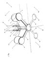
- the basic system of a connecting element 1 shown in FIG. 1 by continuous lines consists of a conical shaped part 3 and the web 4, which is integral with the conical shaped part 3, and the cylindrical shaped part 2, on which the web 4 is inseparable or releasable via locking means 14 is fixed.
- This basic system of the connecting element 1 can, as shown for example by dashed lines in Figure 1, with one or more and the conical mold part 3 identical conical mold parts 3a; 3b; 3x, also with identical webs 4a; 4b; 4x are integrally formed, to be supplemented.
- a connecting element 1 consist of a one-piece connecting element 1, in which two conical shaped parts 3 - 3b offset by 180 ° or from a connecting element 1, in the conical moldings 3 - 3x by 90 ° and or from a connecting element 1, in the conical Shaped parts 3 - 3 twice by 90 ° and once offset by 180 ° or from a connecting element 1, in which two conical mold parts 3, 3a by 90 ° and a conical mold part 3c by 135 ° to the mold parts 3, 3a offset on the cylindrical mold part.
- 2 are defined or consist of a connecting element 1, in which individual conical mold parts 3 - 3x are selectively locked to the desired shape of the system furniture, such as a table or a table system on the cylindrical part 2.
- a connecting element 1, in which two identical conical moldings 3 are releasably fixed to a centrally located cylindrical shaped part 2, is very variable in the connection possibilities of furniture parts 30, 31 - 31x and economical in the production and application and is therefore the preferred connecting element 1 closer Explanation based, wherein the following comments on the attachment of the cylindrical shaped part 2 in the furniture part 30 and the conical design of the lateral surface and the attachment of the conical mold parts 3 - 3x are transferable to an integrally formed connecting element.
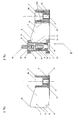
- the basic system of a detachable connecting element 1 shown in FIG. 2 consists of a conical shaped part 3, and the web 4 integrally connected thereto. At the free end of the web 4, a locking means 14 is formed, with which the conical shaped part 3 via the web 4 on the cylindrical Molded part 2 is free of play and fixed in position.
- the cylindrical shaped part 2 consists of a bolt 8 which is formed at the lower end with a rear-turned and diameter-enlarged projection 10 and at the upper end with a threaded bore 39 in which a clamping means 11 can be screwed.
- the clamping means 11 is provided with a directed to the neck 10 of the bolt 8 rear-turned lug 12, which form the attachment points for the locking means 14 of the web 4 with the opposite rear-turned lug 10 of the bolt 8.
- an inner cone 18 is formed in the bolt 8, which cooperates with a korrospondierenden cone 19 in the furniture part 30, which is for example via a subsequent to the cone 19 fastener 35 in the furniture part 30.
- the cone 19 is preferably formed in the region of the largest diameter with an annular groove 22 in which a locking ring 21 is inserted, which cooperates with an annular groove 20 which is laid dekkungsrete the annular groove 22 of the cone 19 in the inner cone 18 of the bolt 8.
- the bolt 8 is additionally provided with a through hole 23 which is axially aligned with a bore 41 which is provided in the clamping means 11.
- a clamping screw 25 is preferably performed, with which the existing bolt 8 and clamping means 11 cylindrical shaped part 2 in a provided in the cone 19 of the furniture part 30 threaded bore 28 can be braced.
- the upper portion of the bore 41 is formed with an enlarged diameter projection 40 for receiving the head of the clamping screw 25, which has a depth that the head of the clamping screw 25 at least flat to the surface of the clamping means 11 closes or the thickness of a auf detailden Decor cover 42 is sunk.
- Fig. 3 shows a conical shaped part 3 with web 4 and locking means 14, which preferably consist of a one-piece casting.
- the locking means 14 located on the free end face 13 of the web 4 preferably consists of two opposing hook-shaped projections 15, 16 and a bearing surface 17 corrosponding to the jacket surface of the bushing 8.
- the locking means 14 with the contact surface 17 and the hook-shaped projections 15, 16 can be used directly be formed on the free end face 13 of the web 4, it is advantageous, however, if the locking means 14 is formed on a widened approach of the web 4, which results in 360 °, for example, when adjoining locking means 14-14x. In this way, a larger-area load bearing of the locking means 14 and thus improved power transmission is achieved on the bolt 8 of the cylindrical molding 2, such that the associated furniture parts 30, 31; 31a; 31b; 31x have a significantly increased stability.
- the lateral surface 6 of the molded part 3 is formed with an axially extending diameter-reduced recess 9, in which a sleeve 7 is used with a conical surface 7a axially stabilized position.
- the sleeve 7 is preferably an exchangeable slot sleeve and advantageously consists of a hard plastic.
- the lateral surface 6 of the molded part 3 may be formed with not shown and evenly offset on the circumference of the molding 3 milled, are used in the conical longitudinal strips 5 detachable or insoluble.
- the conical shaped part 3 can also consist of a one-piece truncated cone, which is provided with or without evenly milled conical longitudinal strips.
- the conical shaped part 3 may additionally be formed with an inner cone 36 and an upwardly adjoining threaded bore 27 in order, if necessary, to clamp the conical shaped part 3 with the furniture part 31 - 31x to be joined.
- Fig. 4 shows a preferred embodiment of the connection between the molded part 3 and the furniture parts 31 - 31x, with the particular a slotted receiving opening 29 in the furniture parts 31- 31x after insertion of the conical molding 3 remains dimensionally stable.
- an at least partially slotted sleeve 32 is inserted congruently with the slot of the slotted receiving opening 29, which is formed with a projection 33 which is against the underlying surface of a furniture part 31 - 31x is supported and the releasable connecting means 37 which are connectable to the adjacent surface of a furniture part 31 - 31x.
- the lug 33 may be formed on the lower side with a fully or partially circumferential or individually offset stabilizing means 38, such as a groove, engaged by at least one stabilizing means 38a, as shown in Fig. 11, on a circumferential flange 34 is formed, which is integral with the conical mold part 3.
- a fully or partially circumferential or individually offset stabilizing means 38 such as a groove
- the receiving opening 29 remains dimensionally stable after insertion of the conical molding 3 and the inherent properties of wood or wood-like materials is counteracted. Consequently, the compound permanently ensures a stable state of the interconnected furniture parts 30, 31 even after repeated assembly and disassembly; 31a; 31b; 31x.
- Fig. 8 and Fig. 9 show a furniture part 30 made of wood or of a metallic material with a single or multiple longitudinally slotted hole 26 for the passage of the web 4; 4a; 4b; 4x, which is integral with the conical molding 3; 3a; 3b; 3x are.
- the cone 19 for receiving the cylindrical shaped part 2 with the fastening means 35 is set in the slit-free continued bore 26 and at the bottom of the bore 26 so that the inner cone 18 of the cylindrical molded part 2 without hindrance and completely with the cone 19 can be braced.
- the bore 26 can also be advantageously continued after the slot depth for the web 4 in unslotted form and also extend completely through the furniture part 30.
- a mounting bush 43 is positioned in the bore 26, which is provided with a connecting means for receiving the Fastener 35 of the cone 19 is formed.
- the fixing means 43 is fixed by means of suitable and not shown axially stable in position in the bore 29 and preferably additionally glued.
- the connecting element 1 is assembled individually according to the desired design of a table or a table system.
- the cylindrical mold part 2 one or more conical mold parts 3 - 3x respectively via the web 4 - 4 x and the locking means arranged thereon 14 - 14x locked free of play.
- the hook-shaped projection 16 of a locking means 14 - 14x inserted into the rearward projection 10 of the bolt 6 and the contact surfaces 17 of each locking 14 - 14x pressed against the corrosponding with the contact surface 17 lateral surface of the bolt 8.
- the clamping means 11 with the locking means 14 - 14x directed rear-turned neck 12 is in the bolt 8, the hook-shaped projection 15 of the locking means 14 - 14x engages in the behind-twisted projection 12 of the clamping means 11, so that the webs used 4 -. 4x stable after storage of the clamping device 11 and free of play on the bolt 8 and thus fixed to the cylindrical mold part 2.
- the connecting element 1 can be designed individually in a very simple manner with identical components and is for the most diverse connection systems of furniture parts 30, 31; 31a; 31b; 31x, especially of tables and table formations, usable.
- connection system with a connecting element 1 assembled in this way, but which can also be a one-piece connecting element 1, is shown in FIG. 10, which, for the sake of simplicity, is only a linear connecting element 1.
- the connection form between the furniture part 31 and the conical shaped part 3 is, in principle, also transferable to the connection forms between the furniture parts 31a-31x and the conical shaped parts 3a-3x.
- the cylindrical shaped part 2 of the connecting means 1 is inserted into a furniture part 30, as shown, for example, in FIGS. 8 and 9.
- the cylindrical shaped part 2 in the slotted hole 26 of the web 4 is performed flush through the slot 4 and the inner cone 18 is received by the cone 19 in the furniture part 30 and thus the cylinder-shaped mold part 2 is position stabilized.
- the cylindrical shaped part 2 is clamped in the cone 19 by means of the clamping screw 25.
- a furniture part 31 in this case a table top with a slotted receiving opening 29 for the implementation of the web 4 is placed on the conical shaped part 2.
- a socket 32 adapted to the slotted receiving opening 29 is inserted and preferably glued in with a projection 33 which is formed with releasable connecting means 37 to the furniture part 31 and a stabilizing means 38.
- the conical molding 3 is formed with an enlarged diameter flange 34 on which a stabilizing means 38 a is laid, as shown in Fig. 11, with the stabilizing agent 38 at the base 33 of the sleeve 32 after placing the furniture part 31, in this case again the table top, cooperates and thus stabilizes the socket in the slotted receiving opening 29.
- the connecting element 1 can also be wholly or partially deeper in the furniture parts 30; 31 - 31x inserted and covered with a decorative cover 42 partially or completely.
Landscapes
- Engineering & Computer Science (AREA)
- General Engineering & Computer Science (AREA)
- Mechanical Engineering (AREA)
- Furniture Connections (AREA)
Applications Claiming Priority (1)
| Application Number | Priority Date | Filing Date | Title |
|---|---|---|---|
| DE200520017024 DE202005017024U1 (de) | 2005-10-31 | 2005-10-31 | Verbindungselement und lösbare Verbindung für Systemmöbel |
Publications (2)
| Publication Number | Publication Date |
|---|---|
| EP1779747A2 true EP1779747A2 (fr) | 2007-05-02 |
| EP1779747A3 EP1779747A3 (fr) | 2011-04-13 |
Family
ID=36500642
Family Applications (1)
| Application Number | Title | Priority Date | Filing Date |
|---|---|---|---|
| EP06022567A Withdrawn EP1779747A3 (fr) | 2005-10-31 | 2006-10-28 | Élément de fixation et système de fixation réversible pour meubles préfabriqués ou sous-assemblés |
Country Status (2)
| Country | Link |
|---|---|
| EP (1) | EP1779747A3 (fr) |
| DE (1) | DE202005017024U1 (fr) |
Cited By (1)
| Publication number | Priority date | Publication date | Assignee | Title |
|---|---|---|---|---|
| CN108999857A (zh) * | 2018-07-27 | 2018-12-14 | 上海壹墨图文设计制作有限公司 | 一种活动支件连接结构 |
Families Citing this family (2)
| Publication number | Priority date | Publication date | Assignee | Title |
|---|---|---|---|---|
| DE202008002538U1 (de) | 2008-02-22 | 2008-06-26 | Trümper, Jörg | Lösbare Verbindung |
| EP4187109A1 (fr) * | 2021-11-30 | 2023-05-31 | Hilti Aktiengesellschaft | Connecteur de panneau en forme d'os |
Family Cites Families (3)
| Publication number | Priority date | Publication date | Assignee | Title |
|---|---|---|---|---|
| FR2425010A1 (fr) * | 1978-05-02 | 1979-11-30 | Foucault Henri De | Dispositif d'assemblage et applications |
| JP2820529B2 (ja) * | 1989-02-09 | 1998-11-05 | ソシエテ、カセス | フレームとフレーム成形型の組み立て装置 |
| DE19522037A1 (de) * | 1995-06-17 | 1996-12-19 | Stoll Sedus Ag | Vorrichtung zum Verbinden einer Möbel-Standsäule mit einem Trägerteil |
-
2005
- 2005-10-31 DE DE200520017024 patent/DE202005017024U1/de not_active Expired - Lifetime
-
2006
- 2006-10-28 EP EP06022567A patent/EP1779747A3/fr not_active Withdrawn
Cited By (2)
| Publication number | Priority date | Publication date | Assignee | Title |
|---|---|---|---|---|
| CN108999857A (zh) * | 2018-07-27 | 2018-12-14 | 上海壹墨图文设计制作有限公司 | 一种活动支件连接结构 |
| CN108999857B (zh) * | 2018-07-27 | 2023-10-03 | 上海壹墨图文设计制作有限公司 | 一种活动支件连接结构 |
Also Published As
| Publication number | Publication date |
|---|---|
| DE202005017024U1 (de) | 2006-05-11 |
| EP1779747A3 (fr) | 2011-04-13 |
Similar Documents
| Publication | Publication Date | Title |
|---|---|---|
| DE102010037837B4 (de) | Tischsystem | |
| EP0606880B1 (fr) | Dispositif de fixation d'un élément en forme de panneau contre un mur ou similaire | |
| DE2625181A1 (de) | Grund- bzw. verstellplatte fuer scharniere, insbesondere fuer moebelscharniere | |
| DE202008007378U1 (de) | Schraubclip | |
| DE2515118A1 (de) | Beschlag zum zusammenbau von zerlegbaren moebeln | |
| EP1779747A2 (fr) | Élément de fixation et système de fixation réversible pour meubles préfabriqués ou sous-assemblés | |
| DE3920959C2 (fr) | ||
| EP3574163B1 (fr) | Set et structure de cadre pour une estrade, une scène et/ou une tribune | |
| DE3507157C2 (de) | Standmöbelsatz | |
| EP2241211B1 (fr) | Système de table | |
| EP1134170B1 (fr) | Structure à assemblage modulaire pour des rayons de stockage | |
| DE4442747C2 (de) | Modulares Regalsystem | |
| DE10030919B4 (de) | Zerlegbarer Profilrohrrahmen sowie Tischsystem mit einem solchen Profilrohrrahmen | |
| AT396005B (de) | Befestigungselement mit einer duebelartigen buchse | |
| DE202007008397U1 (de) | Möbelsystem sowie Möbelstück | |
| DE2549352A1 (de) | Montageelement fuer moebelscharniere | |
| DE102004022471A1 (de) | Verbindungselement | |
| DE19920447C2 (de) | Gestellsystem | |
| DE19703416C2 (de) | Vorrichtung zum Verbinden von Möbelteilen | |
| DE202016001304U1 (de) | Verbindungselement für Bauteile eines Katzenkratzbaums und Katzenkratzbaum mit einem solchen Verbindungselement | |
| AT503129A4 (de) | Verbindungsbeschlag für holzteile | |
| DE7807785U1 (de) | Laufrolle mit einer halterung zu ihrer loesbaren befestigung | |
| DE20307440U1 (de) | Stellfuß | |
| DE202011051042U1 (de) | Verbindungsanordnung und Möbelsystem | |
| DE7119090U (de) | Beschlag zum rechtwinkligen Verbinden zweier Möbelteile |
Legal Events
| Date | Code | Title | Description |
|---|---|---|---|
| PUAI | Public reference made under article 153(3) epc to a published international application that has entered the european phase |
Free format text: ORIGINAL CODE: 0009012 |
|
| AK | Designated contracting states |
Kind code of ref document: A2 Designated state(s): AT BE BG CH CY CZ DE DK EE ES FI FR GB GR HU IE IS IT LI LT LU LV MC NL PL PT RO SE SI SK TR |
|
| AX | Request for extension of the european patent |
Extension state: AL BA HR MK YU |
|
| PUAL | Search report despatched |
Free format text: ORIGINAL CODE: 0009013 |
|
| AK | Designated contracting states |
Kind code of ref document: A3 Designated state(s): AT BE BG CH CY CZ DE DK EE ES FI FR GB GR HU IE IS IT LI LT LU LV MC NL PL PT RO SE SI SK TR |
|
| AX | Request for extension of the european patent |
Extension state: AL BA HR MK RS |
|
| 19U | Interruption of proceedings before grant |
Effective date: 20111026 |
|
| AKX | Designation fees paid |
Designated state(s): AT BE BG CH CY CZ DE DK EE ES FI FR GB GR HU IE IS IT LI LT LU LV MC NL PL PT RO SE SI SK TR |
|
| 19W | Proceedings resumed before grant after interruption of proceedings |
Effective date: 20120301 |
|
| STAA | Information on the status of an ep patent application or granted ep patent |
Free format text: STATUS: THE APPLICATION HAS BEEN WITHDRAWN |
|
| 18W | Application withdrawn |
Effective date: 20120301 |