EP1780119A2 - Système d'ouverture et de fermeture de sécurité pour portes - Google Patents
Système d'ouverture et de fermeture de sécurité pour portes Download PDFInfo
- Publication number
- EP1780119A2 EP1780119A2 EP06380214A EP06380214A EP1780119A2 EP 1780119 A2 EP1780119 A2 EP 1780119A2 EP 06380214 A EP06380214 A EP 06380214A EP 06380214 A EP06380214 A EP 06380214A EP 1780119 A2 EP1780119 A2 EP 1780119A2
- Authority
- EP
- European Patent Office
- Prior art keywords
- door
- opening
- blocking bar
- blocking
- overpressure
- Prior art date
- Legal status (The legal status is an assumption and is not a legal conclusion. Google has not performed a legal analysis and makes no representation as to the accuracy of the status listed.)
- Withdrawn
Links
- 230000000903 blocking effect Effects 0.000 claims abstract description 135
- 230000014759 maintenance of location Effects 0.000 claims abstract description 18
- 230000000295 complement effect Effects 0.000 claims description 7
- 230000001174 ascending effect Effects 0.000 claims description 6
- 238000006073 displacement reaction Methods 0.000 claims description 4
- 230000006835 compression Effects 0.000 claims description 3
- 238000007906 compression Methods 0.000 claims description 3
- 230000009471 action Effects 0.000 claims description 2
- 230000008901 benefit Effects 0.000 description 9
- 238000012423 maintenance Methods 0.000 description 4
- 230000009977 dual effect Effects 0.000 description 1
- 230000000694 effects Effects 0.000 description 1
- 230000007246 mechanism Effects 0.000 description 1
- 238000000034 method Methods 0.000 description 1
- 230000008569 process Effects 0.000 description 1
- 230000000284 resting effect Effects 0.000 description 1
Images






Classifications
-
- B—PERFORMING OPERATIONS; TRANSPORTING
- B64—AIRCRAFT; AVIATION; COSMONAUTICS
- B64C—AEROPLANES; HELICOPTERS
- B64C1/00—Fuselages; Constructional features common to fuselages, wings, stabilising surfaces or the like
- B64C1/14—Windows; Doors; Hatch covers or access panels; Surrounding frame structures; Canopies; Windscreens accessories therefor, e.g. pressure sensors, water deflectors, hinges, seals, handles, latches, windscreen wipers
- B64C1/1407—Doors; surrounding frames
-
- B—PERFORMING OPERATIONS; TRANSPORTING
- B64—AIRCRAFT; AVIATION; COSMONAUTICS
- B64C—AEROPLANES; HELICOPTERS
- B64C1/00—Fuselages; Constructional features common to fuselages, wings, stabilising surfaces or the like
- B64C1/14—Windows; Doors; Hatch covers or access panels; Surrounding frame structures; Canopies; Windscreens accessories therefor, e.g. pressure sensors, water deflectors, hinges, seals, handles, latches, windscreen wipers
-
- B—PERFORMING OPERATIONS; TRANSPORTING
- B64—AIRCRAFT; AVIATION; COSMONAUTICS
- B64D—EQUIPMENT FOR FITTING IN OR TO AIRCRAFT; FLIGHT SUITS; PARACHUTES; ARRANGEMENT OR MOUNTING OF POWER PLANTS OR PROPULSION TRANSMISSIONS IN AIRCRAFT
- B64D29/00—Power-plant nacelles, fairings or cowlings
- B64D29/08—Inspection panels for power plants
-
- B—PERFORMING OPERATIONS; TRANSPORTING
- B64—AIRCRAFT; AVIATION; COSMONAUTICS
- B64D—EQUIPMENT FOR FITTING IN OR TO AIRCRAFT; FLIGHT SUITS; PARACHUTES; ARRANGEMENT OR MOUNTING OF POWER PLANTS OR PROPULSION TRANSMISSIONS IN AIRCRAFT
- B64D41/00—Power installations for auxiliary purposes
-
- E—FIXED CONSTRUCTIONS
- E05—LOCKS; KEYS; WINDOW OR DOOR FITTINGS; SAFES
- E05B—LOCKS; ACCESSORIES THEREFOR; HANDCUFFS
- E05B51/00—Operating or controlling locks or other fastening devices by other non-mechanical means
- E05B51/02—Operating or controlling locks or other fastening devices by other non-mechanical means by pneumatic or hydraulic means
- E05B51/023—Operating or controlling locks or other fastening devices by other non-mechanical means by pneumatic or hydraulic means actuated in response to external pressure, blast or explosion
-
- E—FIXED CONSTRUCTIONS
- E05—LOCKS; KEYS; WINDOW OR DOOR FITTINGS; SAFES
- E05C—BOLTS OR FASTENING DEVICES FOR WINGS, SPECIALLY FOR DOORS OR WINDOWS
- E05C1/00—Fastening devices with bolts moving rectilinearly
- E05C1/02—Fastening devices with bolts moving rectilinearly without latching action
- E05C1/04—Fastening devices with bolts moving rectilinearly without latching action with operating handle or equivalent member rigid with the bolt
-
- E—FIXED CONSTRUCTIONS
- E06—DOORS, WINDOWS, SHUTTERS, OR ROLLER BLINDS IN GENERAL; LADDERS
- E06B—FIXED OR MOVABLE CLOSURES FOR OPENINGS IN BUILDINGS, VEHICLES, FENCES OR LIKE ENCLOSURES IN GENERAL, e.g. DOORS, WINDOWS, BLINDS, GATES
- E06B5/00—Doors, windows, or like closures for special purposes; Border constructions therefor
- E06B5/10—Doors, windows, or like closures for special purposes; Border constructions therefor for protection against air-raid or other war-like action; for other protective purposes
- E06B5/12—Doors, windows, or like closures for special purposes; Border constructions therefor for protection against air-raid or other war-like action; for other protective purposes against air pressure, explosion, or gas
-
- B—PERFORMING OPERATIONS; TRANSPORTING
- B64—AIRCRAFT; AVIATION; COSMONAUTICS
- B64D—EQUIPMENT FOR FITTING IN OR TO AIRCRAFT; FLIGHT SUITS; PARACHUTES; ARRANGEMENT OR MOUNTING OF POWER PLANTS OR PROPULSION TRANSMISSIONS IN AIRCRAFT
- B64D41/00—Power installations for auxiliary purposes
- B64D2041/002—Mounting arrangements for auxiliary power units (APU's)
-
- E—FIXED CONSTRUCTIONS
- E05—LOCKS; KEYS; WINDOW OR DOOR FITTINGS; SAFES
- E05C—BOLTS OR FASTENING DEVICES FOR WINGS, SPECIALLY FOR DOORS OR WINDOWS
- E05C7/00—Fastening devices specially adapted for two wings
Definitions
- This invention belongs to the technical field of safety opening and closing devices and systems for doors, and more particularly to safety opening and closing systems for doors which give access to chambers that could suffer overpressure in the field of aeronautics, more specifically the opening and closing of doors for the chamber in which the auxiliary engine is housed in an aircraft.
- the first of these is that the doors have to open automatically in the event that there exists overpressure in the chamber during the flight, in order to prevent situations of non-permitted loads on the structure.
- the second requirement is one of safety of operation in the opening and/or closing of the doors when maintenance is carried out on the chamber and on the auxiliary engine. If the engine is running on the ground during the maintenance process, it can produce a suction on the doors of the chamber, which, when they close, could trap the ground personnel inside and, if they need to be opened, it could prevent this from happening. In order to avoid this, a controlled and sequential opening/closing control system is required implying a set of defined and sequential operations for being able to open the doors safely.
- the present invention has the aim of overcoming the drawbacks of the mechanisms of the state of the art by means of a opening and secure-closing system for doors.
- Said invention applies to the opening and closing of the doors of compartments in the aeronautical sector, which need safety requirements, and more specifically for the opening and closing of the doors for the chamber which houses the auxiliary engine in an aircraft.
- Said safety opening and closing system comprises a first and a second door for accessing the interior of a chamber; said doors open towards the outside being hinged around separate hinging axes, and both doors present a set of bolts.
- the system of the present invention includes additional means of opening/closing operation which provide safety in the opening and closing thanks to the set of sequential operations that have to be performed on those means of opening/closing for being able to open/close the doors.
- the system presents an overpressure door, which will open in order to prevent overpressure inside the chamber which would give rise to non-permitted loads on the structure.
- Said system of the present invention is characterised in that the overpressure door is provided in the first door or in the second door, it is of a smaller size than those doors, and it opens towards the outside.
- the means of opening/closing operation comprise means of retention between the first door and the second door, in such a way that the second door can only be opened once the first door is open, and the set of first and second doors (1,2) can only be closed by first of all closing the second door (2) and then the first door (1).
- the advantage shown by this configuration of the invention is that it does not need an overpressure door independent of the access doors to the chamber where the auxiliary engine is housed, since said overpressure door is included in one of the doors. Moreover, included in a single assembly are both the safety requirements regarding possible overpressures thanks to the overpressure door and the requirements of controlled and sequential opening of the access doors to the chamber where the auxiliary engine is housed, for possible maintenance operations in a way that is safe, thanks to the additional means of opening/closing operation.
- the means of opening/closing operation are inside the chamber accessed through the door, in such a way that the overpressure door is accessed from the outside of those means of opening/closing operation in order to be able to open and/or close the doors in a way that is controlled and sequential.
- the overpressure door is provided in the first door, secured to it by means of rotary fittings contained in the overpressure door, and said overpressure door comprises some latches with access from the outside for their manual opening.
- said latches are rated for a certain pressure so that they open automatically in the event of emergency due to an overpressure.
- these are located inside the chamber, and in the same door as that where the overpressure door is situated, in other words, the first door, thereby facilitating access to those means once the overpressure door is opened.
- Said means of opening/closing operation comprise a cylindrical blocking bar parallel to the hinging axis for the door, a blocking pin, and a blocking fitting into which the blocking bar is introduced.
- Said blocking bar comprises a guide channel through which the blocking pin of the blocking bar is introduced, and a spring which actuates the bar in its movement for opening and/or closing of the door.
- the blocking bar is introduced into some means of securing of the fixed structure, ensuring the closing of the door, and for the opening, once the overpressure door is open, via it to the blocking bar, and it is pushed actuating the spring, in such a way that the blocking pin is guided by the guide channel, permitting the displacement of the bar, and said blocking pin is secured at one end of said guide channel maintaining the bar in a position free of the securing means of the fixed structure thus permitting that door to be opened.
- This embodiment presents the advantage of simple actuation of the means of opening/closing operation of the door where these means are located.
- this spring is located in the same axis as the blocking bar as a continuation of said blocking bar, in such a way that when this bar moves, the spring is working under compression.
- this is secured to said blocking bar and to the blocking fitting, forming a certain angle with said bar, in such a way that when the blocking bar moves, the spring is working under traction.
- the means of retention of the means of opening/closing operation which are located between the first door and the second door, are angle bars secured to one of the doors and free at the other.
- the blocking bar comprises a stop element for the blocking bar complementary to at least one stop element of the overpressure door, in such a way that once the overpressure door is open and the blocking bar has been displaced permitting the first door to be opened, the stop element of the blocking bar and the stop element of the overpressure door make contact with each other, preventing the involuntary or accidental closure of said pressure door.
- the first door and the second door comprise means of securing that are secured to the fixed structure when said doors are opened, thereby preventing their involuntary or accidental closure, and said means of securing consist of telescopic bars.
- Figures 1 and 2 show an embodiment of the invention which comprises a first door 1 and a second door 2 used for accessing the interior of a chamber.
- this chamber is the compartment where the auxiliary engine of an aircraft is housed.
- These doors open towards the outside, the first door hinging around a first hinging axis 19 and the second door 2 around a second hinging axis 20.
- the first door 1 comprises a set of first bolts 17 and the second door comprises a set of second bolts 18, via which the doors are closed being secured to the surface where these are located.
- the opening and secure-closing system for doors furthermore comprises additional means of opening/closing operation 26 in order to provide security, and an overpressure door 3.
- Said opening and secure-closing system for doors is characterised in that the overpressure door 3 is situated in one of the doors 1,2, being of a smaller size than said doors 1,2 and in that it opens towards the outside.
- the advantage shown by the present invention is that no additional space is necessary for the location of the overpressure door, since it is provided in one of the doors 1,2. Moreover, another advantage is that a single system provides the functions of security in the event of possible overpressures, thanks to the overpressure door 3, and also the function of security thanks to the additional means of opening/closing operation 26.
- the means of opening/closing operation 26 comprise means of retention 10 between the first door 1 and the second door 2, which permit a sequential and controlled opening and closing of said doors 1,2, in such a way that the second door 2 can only be opened once the first door 1 is opened, and the first door 1 can only be closed once the second door 2 is closed.
- Said means of retention can either be secured to the first door 1 and be free at the second door 2, or it can be secured to the second door 2 and be free at the first door 1.
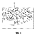
- Figure 8 shows a preferred embodiment of the means of retention 10, in which said means of retention are angle bars 10.
- the advantage of this embodiment is that with some simple configuration and assembly elements the effect is achieved in which if the first door 1 is closed, it will block the opening of the second door 2, which will not be able to open until said first door is open. And for the closure, if the first door 1 is closed first, the angle bars will block the second door 2, and so the assembly will not be able to close. Therefore, first the door 2 has to be closed and then the door 1.
- the means of opening/closing operation 26 are provided in the interior of the chamber to which the first door 1 and the second door 2 give access, and it will only be by opening the overpressure door 3 that access will be able to be had to said means of opening/closing operation 26. Therefore, said overpressure door 3 is the first element that participates in the sequential and controlled opening of the chamber.
- the overpressure door 3 is situated in the first door 1 (though in an alternative embodiment it could be in the second door 2) secured to said first door 1 by means of rotary fittings contained in the overpressure door 6, thanks to which the opening/closing movement is carried out.
- the overpressure door 3 additionally comprises some latches 5 with access from the outside for their manual opening from outside for maintenance operations in the chamber to which the first and second door 1,2 provide access.
- these latches 5 are rated at a determined pressure for the automatic opening of the overpressure door 3 due to an overpressure. Thanks to this dual function, the overpressure door participates in the sequential and controlled opening operation of the chamber, as has been mentioned earlier, and in addition it functions as a safety element which opens in the event that there exist an overpressure inside the chamber.
- the means of opening/closing operation 26 are arranged on the inside surface 27 of said first door 1 (though in an alternative embodiment they could be in the second door 2, always provided they are in the door where the overpressure door 3 is situated). In this way, the opening/closing operation will be simpler thanks to a more comfortable access to the means of opening/closing operation 26 via the overpressure door when said overpressure door is open.
- the means of opening/closing operation 26 additionally comprise a cylindrical blocking bar 4 provided in the direction parallel to the first hinging axis 19 which presents a blocking pin 9 perpendicular to said blocking bar 4.
- Said means of opening/closing operation 26 also comprise a blocking fitting 7 complementary to the blocking bar 4, via which said blocking bar 4 is introduced.
- the blocking fitting 7 comprises a guide channel 21 parallel to the axis of the blocking bar 4 and complementary to the blocking pin 9, via which said blocking pin 9 is introduced.
- the blocking fitting 7 comprises a spring 8 which actuates the blocking bar 4 in its movement for the opening and closing of the first door 1.
- the means of opening/closing operation 26 function in such a way that, with the first door 1 closed, the blocking bar 4 traverses a passage hole of the first door 11 and is introduced into some means of securing of the fixed structure 12, as can be seen in figure 12, ensuring the closure of the door, and for the operation of opening, once the overpressure door 3 is open, via this access is gained to the blocking bar 4 and it is pushed by actuating the spring 8 in such a way that the blocking pin 9 is guided by the guide channel 21 permitting the displacement of the blocking bar 4, and said blocking pin 9 is secured to one end of said guide channel 21 via some means of retention of the guide channel 25 maintaining the blocking bar 4 fixed in a position free of the means of securing of the fixed structure 12, thereby permitting the opening of said first door 1.
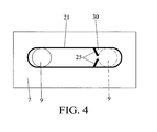
- Figure 4 diagrammatically shows the embodiment of the guide channel 21, together with the blocking pin 9 in two different positions, and the means of retention of the guide channel 25 which block the blocking pin 9.
- the means of retention 10 permit the opening of the second door 2, leaving access to the chamber completely open.
- the advantage of this configuration is the simplicity of the operation, since the operator only has to push the blocking bar 4, with the displacement of this being carried out thanks to the spring 8 and to the blocking pin 9, and the securing of the bar in a position outside of the means of securing of the fixed structure 12 is done efficiently and simply thanks to the securing at the end of the guide channel 21.
- Figures 3 and 6 show an embodiment of the spring 8, in which it is secured to the blocking bar 4 by means of a securing point 24, and is also secured to the blocking fitting 7 in a position intermediate between the passage hole for the first door 11 and the securing point 24 of the spring 8 to the blocking bar 4, in such a way that when said blocking bar 4 moves, the spring 8 is working under traction.
- Figure 7 shows an alternative embodiment of the spring 8, in which said spring 8 is arranged along the longitudinal axis of the blocking bar 4 as a continuation of that blocking bar 4, in such a way that when said blocking bar 4 moves, the spring 8 is working under compression.
- the blocking bar 4 additionally comprises, in a position close to the rotary fittings of the overpressure door 6, at least one stop element of the blocking bar 13, which is complementary to at least one stop element of the overpressure door 14 provided in the overpressure door 3, in a position close to said rotary fittings of the overpressure door 6.
- These stop elements 13, 14 present the advantage that, once the overpressure door 3 is open and the blocking bar 4 has been displaced permitting the first door 1 to be opened, the stop element of the blocking bar 13 and the stop element of the overpressure door 14 make contact with each other, preventing the involuntary closure of the overpressure door 3.
- the stop element of the blocking bar 13 comprises a cylindrical body 22 coaxial with the blocking bar 4 and which can rotate around the latter, and an elongated body 23 in the direction perpendicular to the axis of the cylindrical body 22 and fixed integrally with it.
- the stop element of the blocking bar 13 comprises an elongated body 23 in the direction perpendicular to the axis of the blocking bar 4 and is fixed to said blocking bar 4.
- the guide channel 21 of the blocking fitting 7 has a first advance section of the guide channel 28 parallel to the axis of the blocking bar, a second ascending section 29 of the guide channel and a final section of the guide channel 30, parallel to the first advance section of the guide channel 28 and with a length much less than said first advance section of the guide channel 28, and reversing in the direction of the blocking bar 4, in such a way that the movement of the blocking pin 9 along the second ascending section of the guide channel 29 gives rise to the rotation of the blocking bar 4.
- Said blocking bar 4 drags the stop element of the blocking bar 13 as far as a position in which said stop element of the blocking bar 13 remains in a substantially vertical position and makes contact with the stop element of the overpressure door 14, the blocking pin 9 remaining inserted in the final section of the guide channel 30 owing to the action of the spring 8 and securing the blocking bar 4, thereby preventing the involuntary closure of the overpressure door 3.
- the advantage of this embodiment is that with a single pushing movement by the operator, the blocking bar 4 becomes unblocked, permitting the opening of the first door 1, and the stop element of the blocking bar 13 is located in a contact position with the stop element of the overpressure door 14, thereby preventing the involuntary closure of the overpressure door 3.
- Figure 5 shows the form of the guide channel 9 necessary for this embodiment, as does figure 9.
- both the first door 1 and the second door 2 comprise means of securing of the first and second door 15,16 which are secured to the fixed structure once said first and second door 1,2 are open, thereby preventing their involuntary or accidental closure.
- Said means of securing are telescopic bars which are extended when the first door 1 and the second door 2 are open, resting against the outside surface of the aircraft and preventing the involuntary closure of said doors 1,2.
Landscapes
- Engineering & Computer Science (AREA)
- Aviation & Aerospace Engineering (AREA)
- Mechanical Engineering (AREA)
- Civil Engineering (AREA)
- Structural Engineering (AREA)
- Refrigerator Housings (AREA)
- Lock And Its Accessories (AREA)
- Special Wing (AREA)
- Power-Operated Mechanisms For Wings (AREA)
- Wing Frames And Configurations (AREA)
Applications Claiming Priority (1)
| Application Number | Priority Date | Filing Date | Title |
|---|---|---|---|
| ES200502651A ES2301304B1 (es) | 2005-10-31 | 2005-10-31 | Sistema de apertura y cierre de seguridad para puertas. |
Publications (2)
| Publication Number | Publication Date |
|---|---|
| EP1780119A2 true EP1780119A2 (fr) | 2007-05-02 |
| EP1780119A3 EP1780119A3 (fr) | 2010-07-14 |
Family
ID=37684878
Family Applications (1)
| Application Number | Title | Priority Date | Filing Date |
|---|---|---|---|
| EP06380214A Withdrawn EP1780119A3 (fr) | 2005-10-31 | 2006-07-27 | Système d'ouverture et de fermeture de sécurité pour portes |
Country Status (6)
| Country | Link |
|---|---|
| US (1) | US7938366B2 (fr) |
| EP (1) | EP1780119A3 (fr) |
| BR (1) | BRPI0603141B1 (fr) |
| CA (1) | CA2555444C (fr) |
| ES (1) | ES2301304B1 (fr) |
| RU (1) | RU2391477C2 (fr) |
Cited By (4)
| Publication number | Priority date | Publication date | Assignee | Title |
|---|---|---|---|---|
| CN104401478A (zh) * | 2014-11-27 | 2015-03-11 | 江西洪都航空工业集团有限责任公司 | 一种腹部大开口发动机承力快卸舱门结构 |
| CN105178752A (zh) * | 2015-09-02 | 2015-12-23 | 哈尔滨飞机工业集团有限责任公司 | 一种舱门开启方式快速转换合页机构 |
| EP3360777A1 (fr) * | 2017-02-08 | 2018-08-15 | Airbus Operations S.L. | Système d'ouverture et de fermeture sécurisée des portes d'aéronef |
| EP4098555A1 (fr) * | 2021-06-01 | 2022-12-07 | Airbus Operations GmbH | Unité de porte pour un véhicule |
Families Citing this family (4)
| Publication number | Priority date | Publication date | Assignee | Title |
|---|---|---|---|---|
| BE1020446A3 (nl) * | 2012-01-16 | 2013-10-01 | Cnh Belgium Nv | Een veilige knoper voor een agrarische balenpers. |
| EP2951090B1 (fr) | 2013-01-29 | 2019-01-16 | United Technologies Corporation | Capot avec verrou actionné par pression |
| EP2951091B1 (fr) | 2013-01-29 | 2019-01-09 | United Technologies Corporation | Capot avec verrou à taux limité |
| US10240389B2 (en) * | 2015-09-30 | 2019-03-26 | Arconic Inc. | Pressure relief door |
Family Cites Families (22)
| Publication number | Priority date | Publication date | Assignee | Title |
|---|---|---|---|---|
| US266601A (en) * | 1882-10-31 | Door-bolt | ||
| US1703795A (en) * | 1927-04-09 | 1929-02-26 | Stewart Ross Cliff | Door structure |
| GB1411791A (en) * | 1972-08-03 | 1975-10-29 | British Aircraft Corp Ltd | Door assemblies |
| US4826644A (en) * | 1986-12-01 | 1989-05-02 | Convault, Inc. | Method for entombment of tanks in concrete |
| US4825644A (en) * | 1987-11-12 | 1989-05-02 | United Technologies Corporation | Ventilation system for a nacelle |
| DE4002447C1 (en) * | 1990-01-27 | 1991-03-14 | Deutsche Airbus Gmbh, 2103 Hamburg, De | Decompression panel esp. for aircraft - consists of plate which is releasably held in de-compression opening and consists of two inter-strapped plate parts |
| US5125695A (en) * | 1991-10-02 | 1992-06-30 | Hartwell Max H | Safety latch |
| US5337977A (en) * | 1993-01-29 | 1994-08-16 | The Boeing Company | Vent-latch interlock assembly for an aircraft door |
| US6039287A (en) * | 1996-08-02 | 2000-03-21 | Alliedsignal Inc. | Detachable integral aircraft tailcone and power assembly |
| FR2771459B1 (fr) * | 1997-11-27 | 2000-02-04 | Aerospatiale | Bielle telescopique d'ouverture d'un capot mobile, notamment de nacelle d'un moteur d'avion |
| US6247668B1 (en) * | 1999-07-15 | 2001-06-19 | The Boeing Company | Auxiliary power and thrust unit |
| RU2186710C2 (ru) * | 2000-05-03 | 2002-08-10 | Открытое акционерное общество Таганрогский авиационный научно-технический комплекс им. Г.М.Бериева | Бортовой люк самолета-амфибии |
| US6866226B2 (en) * | 2001-10-04 | 2005-03-15 | Hartwell Corporation | Pressure responsive blowout latch |
| US6663046B2 (en) * | 2001-10-25 | 2003-12-16 | Mark Bogdan Raczkowski | Safety system for cockpit |
| US6830217B2 (en) * | 2002-09-26 | 2004-12-14 | The Boeing Company | Integrated cockpit door lock and access system |
| US6659401B1 (en) * | 2002-11-13 | 2003-12-09 | Robert M. Semprini | Airplane door lock system |
| JP3971313B2 (ja) * | 2003-01-24 | 2007-09-05 | 株式会社ジャムコ | 航空機の操縦室ドア |
| GB0312490D0 (en) * | 2003-06-02 | 2003-07-09 | Rolls Royce Plc | Aeroengine nacelle |
| JP3947511B2 (ja) * | 2003-10-02 | 2007-07-25 | 株式会社ジャムコ | 航空機の操縦室ドア |
| JP3806126B2 (ja) * | 2004-03-18 | 2006-08-09 | 株式会社ジャムコ | コックピットドアのキャッチ装置 |
| FR2911321B1 (fr) * | 2007-01-11 | 2009-07-10 | Airbus Sa Sa | Systeme d'ouverture et de fermeture d'une case de train d'atterissage d'un aeronef |
| EP2215321B1 (fr) * | 2007-11-01 | 2013-07-31 | Adams Rite Aerospace | Mécanisme de verrouillage d'orifice de décompression |
-
2005
- 2005-10-31 ES ES200502651A patent/ES2301304B1/es not_active Expired - Lifetime
-
2006
- 2006-07-27 EP EP06380214A patent/EP1780119A3/fr not_active Withdrawn
- 2006-08-03 CA CA2555444A patent/CA2555444C/fr not_active Expired - Fee Related
- 2006-08-04 US US11/499,915 patent/US7938366B2/en active Active
- 2006-08-07 RU RU2006128614/12A patent/RU2391477C2/ru active
- 2006-08-09 BR BRPI0603141A patent/BRPI0603141B1/pt not_active IP Right Cessation
Non-Patent Citations (1)
| Title |
|---|
| None |
Cited By (8)
| Publication number | Priority date | Publication date | Assignee | Title |
|---|---|---|---|---|
| CN104401478A (zh) * | 2014-11-27 | 2015-03-11 | 江西洪都航空工业集团有限责任公司 | 一种腹部大开口发动机承力快卸舱门结构 |
| CN105178752A (zh) * | 2015-09-02 | 2015-12-23 | 哈尔滨飞机工业集团有限责任公司 | 一种舱门开启方式快速转换合页机构 |
| CN105178752B (zh) * | 2015-09-02 | 2017-04-12 | 哈尔滨飞机工业集团有限责任公司 | 一种舱门开启方式快速转换合页机构 |
| EP3360777A1 (fr) * | 2017-02-08 | 2018-08-15 | Airbus Operations S.L. | Système d'ouverture et de fermeture sécurisée des portes d'aéronef |
| US10919611B2 (en) | 2017-02-08 | 2021-02-16 | Airbus Operations S.L. | Opening and secure-closing system |
| EP4098555A1 (fr) * | 2021-06-01 | 2022-12-07 | Airbus Operations GmbH | Unité de porte pour un véhicule |
| EP4098556A1 (fr) * | 2021-06-01 | 2022-12-07 | Airbus Operations GmbH | Unité de porte pour un véhicule |
| US12546149B2 (en) | 2021-06-01 | 2026-02-10 | Airbus Operations Gmbh | Door unit for a vehicle |
Also Published As
| Publication number | Publication date |
|---|---|
| US7938366B2 (en) | 2011-05-10 |
| CA2555444A1 (fr) | 2007-04-30 |
| RU2391477C2 (ru) | 2010-06-10 |
| US20070145189A1 (en) | 2007-06-28 |
| ES2301304B1 (es) | 2009-05-01 |
| BRPI0603141B1 (pt) | 2016-07-05 |
| BRPI0603141A (pt) | 2007-08-14 |
| CA2555444C (fr) | 2012-04-17 |
| EP1780119A3 (fr) | 2010-07-14 |
| ES2301304A1 (es) | 2008-06-16 |
| RU2006128614A (ru) | 2008-02-20 |
Similar Documents
| Publication | Publication Date | Title |
|---|---|---|
| EP2347076B1 (fr) | Mécanisme d'actionnement pour parties mobiles de meuble | |
| EP3990344B1 (fr) | Dispositif pour empêcher l'accès à une zone d'un avion | |
| EP0803630B1 (fr) | Dispositif de commande hydraulique | |
| DE102011004400A1 (de) | Türsystem mit Aktor | |
| CA2555444C (fr) | Systeme d'ouverture et de fermeture securitaire pour portes | |
| EP1534588B1 (fr) | Porte d'avion avec mecanisme d'ouverture et dispositif pour avertir d'une pression differentielle lors de l'ouverture de la porte d'avion sous pression | |
| EP3275779B1 (fr) | Interface de transfert de charge pour une portière de véhicule, en particulier pour une porte de cabine d'aéronef | |
| EP1332965A1 (fr) | Sas d'accès à un poste de commande d'un moyen de transport, notamment d'un avion | |
| EP2157396B1 (fr) | Porte de véhicule pour véhicules blindés comportant un pêne de protection contre les mines | |
| DE102014114945A1 (de) | Kraftfahrzeugtürschloss | |
| WO2003097456A1 (fr) | Compartiment a bagages abaissable a verrouillage par ressort a pression de gaz | |
| EP3360777B1 (fr) | Système d'ouverture et de fermeture sécurisée des portes d'aéronef | |
| EP4098555A1 (fr) | Unité de porte pour un véhicule | |
| DE19944407A1 (de) | Türschloß mit Öffnungshilfe | |
| DE102005035006A1 (de) | Vorrichtung zur Aufstellung einer Fahrzeugtür | |
| DE4007493C2 (fr) | ||
| EP3287579B1 (fr) | Dispositif de fermeture pour porte | |
| WO2016116526A1 (fr) | Entraînement de porte comprenant un entraînement principal et un entraînement auxiliaire et éléments fonctionnels supplémentaires | |
| EP3169572B1 (fr) | Système de verrouillage | |
| EP1189178B1 (fr) | Dispositif de passage | |
| DE102013202801B4 (de) | Einrichtung zur motorischen Betätigung einer Kraftfahrzeug-Türe mit Feststellfunktion | |
| DE102019112336A1 (de) | Türeinheit für ein Fahrzeug | |
| EP3617432A1 (fr) | Dispositif de fermeture pour une porte | |
| EP3334877B1 (fr) | Dispositif de verrouillage de vantail coulissant | |
| DE10023259A1 (de) | Betätigungsanordnung zum Öffnen und Schließen von schwenkbaren Fahrzeugflügeln |
Legal Events
| Date | Code | Title | Description |
|---|---|---|---|
| PUAI | Public reference made under article 153(3) epc to a published international application that has entered the european phase |
Free format text: ORIGINAL CODE: 0009012 |
|
| AK | Designated contracting states |
Kind code of ref document: A2 Designated state(s): AT BE BG CH CY CZ DE DK EE ES FI FR GB GR HU IE IS IT LI LT LU LV MC NL PL PT RO SE SI SK TR |
|
| AX | Request for extension of the european patent |
Extension state: AL BA HR MK YU |
|
| RIN1 | Information on inventor provided before grant (corrected) |
Inventor name: GARCIA PATINO, MARIA ARANZAZU Inventor name: MARQUEZ GAVILAN, ANTONIO Inventor name: THOMAS, STEFFAN PRYS Inventor name: MARTIN CALVO, DAVID Inventor name: ROJO SAIZ, NICOLAS Inventor name: MELIAN BRINQUIS, JUAN PABLO Inventor name: SEN PACIOS, JOSE LUIS Inventor name: ROJO CARRION, JOSE ALBERTO Inventor name: MARTINEZ RUEDA, JOSE ROMAN |
|
| RIN1 | Information on inventor provided before grant (corrected) |
Inventor name: GARCIA PATINO, MARIA ARANZAZU Inventor name: MARQUEZ GAVILAN, ANTONIO Inventor name: THOMAS, STEFFAN PRYS Inventor name: MARTIN CALVO, DAVID Inventor name: ROJO SAIZ, NICOLAS Inventor name: MELIAN BRINQUIS, JUAN PABLO Inventor name: SEN PACIOS, JOSE LUIS Inventor name: ROJO CARRION, JOSE ALBERTO Inventor name: MARTINEZ RUEDA, JOSE ROMAN |
|
| RAP1 | Party data changed (applicant data changed or rights of an application transferred) |
Owner name: AIRBUS OPERATIONS S.L. |
|
| PUAL | Search report despatched |
Free format text: ORIGINAL CODE: 0009013 |
|
| AK | Designated contracting states |
Kind code of ref document: A3 Designated state(s): AT BE BG CH CY CZ DE DK EE ES FI FR GB GR HU IE IS IT LI LT LU LV MC NL PL PT RO SE SI SK TR |
|
| AX | Request for extension of the european patent |
Extension state: AL BA HR MK RS |
|
| AKY | No designation fees paid | ||
| REG | Reference to a national code |
Ref country code: DE Ref legal event code: R108 Effective date: 20110222 Ref country code: DE Ref legal event code: 8566 |
|
| STAA | Information on the status of an ep patent application or granted ep patent |
Free format text: STATUS: THE APPLICATION IS DEEMED TO BE WITHDRAWN |
|
| 18D | Application deemed to be withdrawn |
Effective date: 20110115 |