EP1780124B1 - Dispositif pour décomposer des tourbillons dans un éjecteur - Google Patents
Dispositif pour décomposer des tourbillons dans un éjecteur Download PDFInfo
- Publication number
- EP1780124B1 EP1780124B1 EP06122847A EP06122847A EP1780124B1 EP 1780124 B1 EP1780124 B1 EP 1780124B1 EP 06122847 A EP06122847 A EP 06122847A EP 06122847 A EP06122847 A EP 06122847A EP 1780124 B1 EP1780124 B1 EP 1780124B1
- Authority
- EP
- European Patent Office
- Prior art keywords
- eductor
- flow
- power unit
- inlet
- housing
- Prior art date
- Legal status (The legal status is an assumption and is not a legal conclusion. Google has not performed a legal analysis and makes no representation as to the accuracy of the status listed.)
- Expired - Fee Related
Links
- ZBMRKNMTMPPMMK-UHFFFAOYSA-N 2-amino-4-[hydroxy(methyl)phosphoryl]butanoic acid;azane Chemical compound [NH4+].CP(O)(=O)CCC(N)C([O-])=O ZBMRKNMTMPPMMK-UHFFFAOYSA-N 0.000 title 1
- 238000011144 upstream manufacturing Methods 0.000 claims description 7
- 239000007789 gas Substances 0.000 description 32
- 238000001816 cooling Methods 0.000 description 5
- 239000000463 material Substances 0.000 description 2
- 230000004323 axial length Effects 0.000 description 1
- 230000007613 environmental effect Effects 0.000 description 1
- 230000007246 mechanism Effects 0.000 description 1
- 238000012986 modification Methods 0.000 description 1
- 230000004048 modification Effects 0.000 description 1
- 239000007858 starting material Substances 0.000 description 1
- 230000001629 suppression Effects 0.000 description 1
Images

Classifications
-
- B—PERFORMING OPERATIONS; TRANSPORTING
- B64—AIRCRAFT; AVIATION; COSMONAUTICS
- B64D—EQUIPMENT FOR FITTING IN OR TO AIRCRAFT; FLIGHT SUITS; PARACHUTES; ARRANGEMENT OR MOUNTING OF POWER PLANTS OR PROPULSION TRANSMISSIONS IN AIRCRAFT
- B64D41/00—Power installations for auxiliary purposes
-
- F—MECHANICAL ENGINEERING; LIGHTING; HEATING; WEAPONS; BLASTING
- F01—MACHINES OR ENGINES IN GENERAL; ENGINE PLANTS IN GENERAL; STEAM ENGINES
- F01D—NON-POSITIVE DISPLACEMENT MACHINES OR ENGINES, e.g. STEAM TURBINES
- F01D25/00—Component parts, details, or accessories, not provided for in, or of interest apart from, other groups
- F01D25/30—Exhaust heads, chambers, or the like
-
- F—MECHANICAL ENGINEERING; LIGHTING; HEATING; WEAPONS; BLASTING
- F02—COMBUSTION ENGINES; HOT-GAS OR COMBUSTION-PRODUCT ENGINE PLANTS
- F02K—JET-PROPULSION PLANTS
- F02K1/00—Plants characterised by the form or arrangement of the jet pipe or nozzle; Jet pipes or nozzles peculiar thereto
- F02K1/38—Introducing air inside the jet
- F02K1/386—Introducing air inside the jet mixing devices in the jet pipe, e.g. for mixing primary and secondary flow
-
- B—PERFORMING OPERATIONS; TRANSPORTING
- B64—AIRCRAFT; AVIATION; COSMONAUTICS
- B64D—EQUIPMENT FOR FITTING IN OR TO AIRCRAFT; FLIGHT SUITS; PARACHUTES; ARRANGEMENT OR MOUNTING OF POWER PLANTS OR PROPULSION TRANSMISSIONS IN AIRCRAFT
- B64D41/00—Power installations for auxiliary purposes
- B64D2041/002—Mounting arrangements for auxiliary power units (APU's)
-
- F—MECHANICAL ENGINEERING; LIGHTING; HEATING; WEAPONS; BLASTING
- F05—INDEXING SCHEMES RELATING TO ENGINES OR PUMPS IN VARIOUS SUBCLASSES OF CLASSES F01-F04
- F05D—INDEXING SCHEME FOR ASPECTS RELATING TO NON-POSITIVE-DISPLACEMENT MACHINES OR ENGINES, GAS-TURBINES OR JET-PROPULSION PLANTS
- F05D2220/00—Application
- F05D2220/50—Application for auxiliary power units (APU's)
-
- F—MECHANICAL ENGINEERING; LIGHTING; HEATING; WEAPONS; BLASTING
- F05—INDEXING SCHEMES RELATING TO ENGINES OR PUMPS IN VARIOUS SUBCLASSES OF CLASSES F01-F04
- F05D—INDEXING SCHEME FOR ASPECTS RELATING TO NON-POSITIVE-DISPLACEMENT MACHINES OR ENGINES, GAS-TURBINES OR JET-PROPULSION PLANTS
- F05D2240/00—Components
- F05D2240/10—Stators
- F05D2240/12—Fluid guiding means, e.g. vanes
-
- F—MECHANICAL ENGINEERING; LIGHTING; HEATING; WEAPONS; BLASTING
- F05—INDEXING SCHEMES RELATING TO ENGINES OR PUMPS IN VARIOUS SUBCLASSES OF CLASSES F01-F04
- F05D—INDEXING SCHEME FOR ASPECTS RELATING TO NON-POSITIVE-DISPLACEMENT MACHINES OR ENGINES, GAS-TURBINES OR JET-PROPULSION PLANTS
- F05D2250/00—Geometry
- F05D2250/10—Two-dimensional
- F05D2250/13—Two-dimensional trapezoidal
-
- F—MECHANICAL ENGINEERING; LIGHTING; HEATING; WEAPONS; BLASTING
- F05—INDEXING SCHEMES RELATING TO ENGINES OR PUMPS IN VARIOUS SUBCLASSES OF CLASSES F01-F04
- F05D—INDEXING SCHEME FOR ASPECTS RELATING TO NON-POSITIVE-DISPLACEMENT MACHINES OR ENGINES, GAS-TURBINES OR JET-PROPULSION PLANTS
- F05D2250/00—Geometry
- F05D2250/30—Arrangement of components
- F05D2250/31—Arrangement of components according to the direction of their main axis or their axis of rotation
- F05D2250/312—Arrangement of components according to the direction of their main axis or their axis of rotation the axes being parallel to each other
-
- F—MECHANICAL ENGINEERING; LIGHTING; HEATING; WEAPONS; BLASTING
- F05—INDEXING SCHEMES RELATING TO ENGINES OR PUMPS IN VARIOUS SUBCLASSES OF CLASSES F01-F04
- F05D—INDEXING SCHEME FOR ASPECTS RELATING TO NON-POSITIVE-DISPLACEMENT MACHINES OR ENGINES, GAS-TURBINES OR JET-PROPULSION PLANTS
- F05D2260/00—Function
- F05D2260/20—Heat transfer, e.g. cooling
- F05D2260/221—Improvement of heat transfer
-
- F—MECHANICAL ENGINEERING; LIGHTING; HEATING; WEAPONS; BLASTING
- F05—INDEXING SCHEMES RELATING TO ENGINES OR PUMPS IN VARIOUS SUBCLASSES OF CLASSES F01-F04
- F05D—INDEXING SCHEME FOR ASPECTS RELATING TO NON-POSITIVE-DISPLACEMENT MACHINES OR ENGINES, GAS-TURBINES OR JET-PROPULSION PLANTS
- F05D2260/00—Function
- F05D2260/60—Fluid transfer
- F05D2260/601—Fluid transfer using an ejector or a jet pump
-
- Y—GENERAL TAGGING OF NEW TECHNOLOGICAL DEVELOPMENTS; GENERAL TAGGING OF CROSS-SECTIONAL TECHNOLOGIES SPANNING OVER SEVERAL SECTIONS OF THE IPC; TECHNICAL SUBJECTS COVERED BY FORMER USPC CROSS-REFERENCE ART COLLECTIONS [XRACs] AND DIGESTS
- Y02—TECHNOLOGIES OR APPLICATIONS FOR MITIGATION OR ADAPTATION AGAINST CLIMATE CHANGE
- Y02T—CLIMATE CHANGE MITIGATION TECHNOLOGIES RELATED TO TRANSPORTATION
- Y02T50/00—Aeronautics or air transport
- Y02T50/60—Efficient propulsion technologies, e.g. for aircraft
Definitions
- the present invention relates to an eductor and, more particularly, to mechanisms for minimizing the impact of swirling motion of exhaust gas that enters the eductor.
- auxiliary power units are used in aircraft to provide electrical power and compressed air to various parts therein.
- APU auxiliary power units
- the APU can power the electrical systems, environmental control systems, air drive hydraulic pumps, and the starters for the engines.
- the APU may provide pneumatic and/or electric power to the aircraft.
- the APU is located in the aft section of the aircraft, at or near the tailcone section.
- the APU may communicate with an opening in the aircraft fuselage to allow exhaust gas from the APU and other components to flow therethrough.
- an eductor is mounted between the APU and the fuselage opening.
- the eductor is configured to provide APU cooling, compartment cooling, oil cooling, and an interface for the dumping of surge bleed control air, and the eductor-cooled gas is either redirected back to the APU or to other components of the aircraft or is exhausted out the fuselage opening.
- the eductor includes an inlet, an outlet, and a flow path therebetween and may include an oil cooler coupled thereto.
- the eductor inlet is suitably sized to receive a portion of the APU or other component disposed between the APU and eductor to form a radial gap therebetween.
- the radial gap may communicate with other components of the aircraft, such as, for example, a bleed air plenum or the oil cooler.
- an eductor is needed that is simple and inexpensive to implement.
- the present invention provides a system in an aircraft that includes a power unit and an eductor. This invention also applies to helicopters and turboprop aircraft that include a turboshaft/turboprop engine and an eductor.
- the invention consists in an aircraft system comprising:
- the power unit may be a turboshaft/turboprop engine.
- FIG. 1 illustrates a housing 100 within which a power unit 102 and an eductor 104 are disposed.
- the housing 100 which may be an aircraft tailcone or helicopter housing, is generally conical and has a sidewall 103 and inlet and exhaust openings 105, 106 that are formed therein.
- the power unit 102 which may be an auxiliary power unit (“APU") or a turboshaft/turboprop engine, may be used to drive a number of non-illustrated devices, including, for example, a gearbox, a generator, or a load compressor, is mounted within the housing 100 and receives air from an inlet duct 107 that extends between the power unit 102 and the inlet opening 105.
- APU auxiliary power unit
- turboshaft/turboprop engine may be used to drive a number of non-illustrated devices, including, for example, a gearbox, a generator, or a load compressor, is mounted within the housing 100 and receives air from an inlet duct 107 that extend
- the power unit 102 includes a nozzle 108 that communicates with the eductor 104. It will be appreciated that the power unit 102 and eductor 104 may indirectly or directly communicate with each other. In any case, exhaust gas from the power unit 102 flows through the eductor 104 and an exhaust duct 109 and exits the aircraft via the exhaust opening 106.
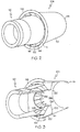
- the eductor 104 shown in more detail in FIGs. 2 and 3 , includes a housing 112 and a plurality of flow straighteners 114 disposed therein.
- the housing 112 is generally cylindrical and has an inlet 116, an outlet 118, and an inner surface 120.
- the inlet 116 receives power unit exhaust gas and is preferably configured to surround the nozzle 108.
- the power unit 102 may communicate with the eductor 104 through an intermediate component, such as a mixer and the inlet 116 may be configured accordingly.
- the housing 112 is dimensioned to form a radial gap 122 between the inlet 116 and nozzle 108 to provide communication between other spaces in the tailcone 100 or other aircraft components, such as a bleed air plenum or an oil cooler, and the eductor 104.
- the outlet 118 communicates with the exhaust opening 106 to remove the power unit exhaust gas from the aircraft.
- the inner surface 120 defines a flow passage 124 that extends between the inlet 116 and outlet 118.
- the flow passage 124 is depicted as being substantially cylindrical, it may have any other suitable configuration for increasing the efficiency of cooling the exhaust gas and directing the exhaust gas outward.
- the flow passage 124 may be a converging or diverging flowpath.
- the flow straighteners 114 are disposed within the flow passage 124 and are configured to reduce the swirling movement of the exhaust gas as it travels therethrough.
- the flow straighteners 114 each extend radially inwardly from the eductor inner surface 120.
- the flow straighteners 114 may be integrally formed as part of the eductor 104, or may be separately manufactured from the eductor 104 and subsequently coupled to the eductor inner surface 120.
- the flow straighteners 114 may be constructed from any material suitable for withstanding the high temperatures of the power unit exhaust gas.
- the flow straighteners 114 are preferably substantially evenly aligned at one end of the eductor 104, most preferably, adjacent the inlet 116. Additionally, as shown in FIGs. 2 and 3 , the flow straighteners 114 are preferably evenly spaced apart from one another. Although a total of sixteen flow straighteners 114 are shown in FIGs. 2 and 3 , it will be appreciated that the particular number of flow straighteners 114 used may depend, in part, on the size of the eductor housing112 and the length of the flow passage 124; accordingly, more or fewer flow straighteners 114 may alternatively be employed.
- the flow straighteners 114 are illustrated as extending partially along the length of the flow passage 124, the flow straighteners 114 may alternatively extend along the entire length of the flow passage 124.
- Each of the flow straighteners 114 preferably has substantially the same axial length, as shown in FIG. 3 .
- the flow straighteners 114 may alternatively each have varying lengths.
- the angular spacing of the flow strengtheners may also be uneven to reduce vibration characteristics of the system.
- each of the flow straighteners 114 may have any one of numerous suitable configurations to substantially remove the swirling motion of the exhaust gas and to direct the gas along a relatively straight flow path through the eductor 104.
- each of the flow straighteners 114 is substantially flat.
- each flow straightener 114 preferably has a trapezoidal shape; however, in some instances, it may be preferable for the flow straightener 114 to have a rectangular, square, or other suitable polygonal shape. In other instances, some of the flow straighteners 114 may vary in shape.
- the flow straighteners 114 depicted in FIG. 3 have sharp corners, it will be appreciated that the corners may alternatively be curved.
- each flow straightener 114 includes an angled upstream edge 128, a downstream edge 130, and two side edges 132, 134 therebetween.
- the upstream edge 128 is configured to be angled at least about 30 degrees relative to the eductor inner surface 120.
- any other suitable angle may be used.
- the embodiment shown in FIG. 3 illustrates the two side edges 132, 134 as being substantially parallel with each other, as alluded to above, it will be appreciated that the side edges 132, 134 may alternatively be non-parallel.
- one of the side edges 132 is coupled to the eductor inner surface 120, while the other side edge 134 is disposed in the flow passage 124, as shown in FIG. 3 .
- a ring 136 or similar device may be coupled to each of the side edges 134 disposed in the flow passage 124 for maintaining the flow straighteners 114 in place.
- the exhaust gas exits the power unit 102 and is received by the eductor inlet 116 in a swirling motion
- the exhaust gas may be mixed with other gases, such as bleed air, from other aircraft components, before reaching the eductor inlet 116.
- the flow straighteners 114 divide the gases into a plurality of gas streams. As the gas streams travel between the flow straighteners 114, the flow straighteners 114 straighten the flow, and eliminate or significantly reduce the swirling motion of the gas.
- the flow straighteners 114 in the eductor 104 are simple and inexpensive to implement therein. Additionally, the flow straighteners 114 may be easily retrofitted into existing eductors.
Landscapes
- Engineering & Computer Science (AREA)
- Mechanical Engineering (AREA)
- General Engineering & Computer Science (AREA)
- Aviation & Aerospace Engineering (AREA)
- Chemical & Material Sciences (AREA)
- Combustion & Propulsion (AREA)
- Jet Pumps And Other Pumps (AREA)
Claims (7)
- Système d'aéronef comprenant :une unité d'alimentation en puissance (102) ayant un bec (108), l'unité d'alimentation en puissance étant configurée pour faire sortir les gaz dont une partie s'écoule à travers le bec dans un mouvement de tourbillonnement ; etun éjecteur (104) en communication avec l'unité d'alimentation en puissance, l'éjecteur comprenant :caractérisé en ce que :un boîtier ayant un orifice d'admission (116), un orifice de sortie (118) et une surface intérieure (120) qui définit un passage d'écoulement (124), l'orifice d'admission étant configuré pour entourer au moins une partie du bec et pour recevoir le gaz et l'orifice de sortie étant configuré pour faire sortir le gaz ; etune pluralité de dispositifs de renfort de flux (114) s'étendant dans le plan radial vers l'intérieur de la surface intérieure du boîtier dans le passage d'écoulement et étant configurés pour réduire le tourbillonnement du gaz les traversant ;un anneau (136) est disposé dans le passage ; etchaque dispositif de renfort de flux comprend un bord en amont (128), un bord en aval (130), un premier bord latéral (138) s'étendant entre eux et un second bord latéral (134) pour l'essentiel parallèle au premier bord latéral (132), dans lequel :les bords en amont forment un angle par rapport à la surface intérieure du boîtier, les premiers bords latéraux étant couplés à la surface intérieure du boîtier et les seconds bords latéraux étant chacun couplés à l'anneau.
- Système selon la revendication 1, dans lequel la pluralité de dispositifs de renfort de flux (114) sont sensiblement alignés au niveau de l'orifice d'admission du boîtier (116) et sont équidistants les uns par rapport aux autres autour de la surface intérieure du boîtier (120).
- Système selon la revendication 1, dans lequel la pluralité de dispositifs de renfort de flux (114) sont disposés à proximité de l'orifice d'admission du boîtier (116).
- Système selon la revendication 1, dans lequel au moins un des dispositifs de renfort de flux (114) prend une forme trapézoïdale.
- Système selon la revendication 1, dans lequel chacun des bords en aval (130) de la pluralité de dispositifs de renfort de flux (114) sont alignés entre eux.
- Système selon la revendication 1, dans lequel l'unité d'alimentation en puissance (102) est une unité d'alimentation en puissance auxiliaire.
- Système selon la revendication 1, dans lequel l'unité d'alimentation en puissance (102) est un turbomoteur.
Applications Claiming Priority (1)
| Application Number | Priority Date | Filing Date | Title |
|---|---|---|---|
| US11/259,700 US7500353B2 (en) | 2005-10-25 | 2005-10-25 | Eductor swirl buster |
Publications (3)
| Publication Number | Publication Date |
|---|---|
| EP1780124A2 EP1780124A2 (fr) | 2007-05-02 |
| EP1780124A3 EP1780124A3 (fr) | 2008-09-10 |
| EP1780124B1 true EP1780124B1 (fr) | 2010-03-03 |
Family
ID=37591866
Family Applications (1)
| Application Number | Title | Priority Date | Filing Date |
|---|---|---|---|
| EP06122847A Expired - Fee Related EP1780124B1 (fr) | 2005-10-25 | 2006-10-24 | Dispositif pour décomposer des tourbillons dans un éjecteur |
Country Status (4)
| Country | Link |
|---|---|
| US (1) | US7500353B2 (fr) |
| EP (1) | EP1780124B1 (fr) |
| CA (1) | CA2565216A1 (fr) |
| DE (1) | DE602006012599D1 (fr) |
Families Citing this family (9)
| Publication number | Priority date | Publication date | Assignee | Title |
|---|---|---|---|---|
| US7350619B2 (en) * | 2004-09-23 | 2008-04-01 | Honeywell International, Inc. | Auxiliary power unit exhaust duct with muffler incorporating an externally replaceable acoustic liner |
| ES2488404T3 (es) * | 2011-03-07 | 2014-08-27 | Eads Construcciones Aeronáuticas, S.A. | Sistema de evacuación de flujo para un motor de aeronave |
| US20130087632A1 (en) * | 2011-10-11 | 2013-04-11 | Patrick Germain | Gas turbine engine exhaust ejector nozzle with de-swirl cascade |
| US8956106B2 (en) | 2011-12-20 | 2015-02-17 | General Electric Company | Adaptive eductor system |
| FR2986275B1 (fr) * | 2012-02-01 | 2016-07-01 | Turbomeca | Procede d'ejection de gaz d'echappement de turbine a gaz et ensemble d'echappement de configuration optimisee |
| US10612421B2 (en) | 2015-03-04 | 2020-04-07 | Sikorsky Aircraft Corporation | Gas turbine exhaust assembly |
| US10415502B2 (en) * | 2017-09-11 | 2019-09-17 | Honeywell International Inc. | Swirling flow eductor system and method |
| PL426033A1 (pl) | 2018-06-22 | 2020-01-02 | General Electric Company | Płynowe pompy strumieniowe parowe, a także układy i sposoby porywania płynu przy użyciu płynowych pomp strumieniowych parowych |
| US11614032B2 (en) * | 2021-01-06 | 2023-03-28 | The Boeing Company | APU eductor plenum flow stability splitter |
Family Cites Families (16)
| Publication number | Priority date | Publication date | Assignee | Title |
|---|---|---|---|---|
| US2735499A (en) * | 1956-02-21 | ehlers | ||
| US3048376A (en) | 1958-04-09 | 1962-08-07 | Curtiss Wright Corp | Fluid mixing apparatus |
| US3710890A (en) | 1971-09-27 | 1973-01-16 | Boeing Co | Aircraft engine noise suppression |
| US4147029A (en) | 1976-01-02 | 1979-04-03 | General Electric Company | Long duct mixed flow gas turbine engine |
| US4045957A (en) | 1976-02-20 | 1977-09-06 | United Technologies Corporation | Combined guide vane and mixer for a gas turbine engine |
| US4145878A (en) | 1977-12-15 | 1979-03-27 | United Technologies Corp. | Vorbix augmenter configuration |
| US4819425A (en) | 1982-03-18 | 1989-04-11 | The Boeing Company | Primary-secondary ventilated flow mixer nozzle for high bypass turbo fan jet propulsion system |
| US4548034A (en) | 1983-05-05 | 1985-10-22 | Rolls-Royce Limited | Bypass gas turbine aeroengines and exhaust mixers therefor |
| US5517865A (en) | 1991-06-13 | 1996-05-21 | General Electric Company | Vortex suppression for an eductor |
| US5265408A (en) | 1992-02-13 | 1993-11-30 | Allied-Signal Inc. | Exhaust eductor cooling system |
| US5381655A (en) | 1993-05-10 | 1995-01-17 | General Electric Company | Admission mixing duct assembly |
| US5706651A (en) | 1995-08-29 | 1998-01-13 | Burbank Aeronautical Corporation Ii | Turbofan engine with reduced noise |
| US6615576B2 (en) | 2001-03-29 | 2003-09-09 | Honeywell International Inc. | Tortuous path quiet exhaust eductor system |
| JP4743465B2 (ja) | 2001-04-19 | 2011-08-10 | 株式会社Ihi | ジェットエンジン用ローブミキサー |
| US6880494B2 (en) * | 2003-07-22 | 2005-04-19 | Karl V. Hoose | Toroidal internal combustion engine |
| US6988674B2 (en) * | 2004-06-08 | 2006-01-24 | General Electric Company | Method and apparatus for suppressing infrared signatures |
-
2005
- 2005-10-25 US US11/259,700 patent/US7500353B2/en not_active Expired - Fee Related
-
2006
- 2006-10-23 CA CA002565216A patent/CA2565216A1/fr not_active Abandoned
- 2006-10-24 EP EP06122847A patent/EP1780124B1/fr not_active Expired - Fee Related
- 2006-10-24 DE DE602006012599T patent/DE602006012599D1/de active Active
Also Published As
| Publication number | Publication date |
|---|---|
| US7500353B2 (en) | 2009-03-10 |
| CA2565216A1 (fr) | 2007-04-25 |
| US20070089396A1 (en) | 2007-04-26 |
| EP1780124A2 (fr) | 2007-05-02 |
| EP1780124A3 (fr) | 2008-09-10 |
| DE602006012599D1 (de) | 2010-04-15 |
Similar Documents
| Publication | Publication Date | Title |
|---|---|---|
| CN104334835B (zh) | 高压消声装置 | |
| JP5264184B2 (ja) | ガスタービンエンジンにおけるブリード通路用のブリード構造体 | |
| CA2746909C (fr) | Systeme d'assourdissement du bruit a pression differentielle elevee | |
| CN106948885B (zh) | 在燃气涡轮发动机内部中用于燃烧区段上游的流控制表面 | |
| US9057329B2 (en) | Turboprop engine systems with noise reducing inlet assemblies | |
| EP3163054A1 (fr) | Procédé et système d'atténuation des résonances de cavité | |
| EP3171009B1 (fr) | Capot de compression pour échappement de moteur à réaction | |
| EP1788310A2 (fr) | Système pour turbines à gaz permettant de coupler le flux d'air issu du compresseur centrifuge à la chambre de combustion axiale | |
| EP3208422A1 (fr) | Profil aérodynamique comportant des trous de liaison | |
| EP1780124B1 (fr) | Dispositif pour décomposer des tourbillons dans un éjecteur | |
| US20180274370A1 (en) | Engine component for a gas turbine engine | |
| EP3156598A1 (fr) | Tuyère pour moteur à turbine à gaz | |
| EP2987988B1 (fr) | Système d'admission d'avion à faible bruit | |
| EP1748177B1 (fr) | Agencement compact et léger du plenum de refroidisseur d'huile et du plenum de l'enlèvement air dans un ejecteur d'évacuation | |
| EP1856398B1 (fr) | Structure de ventilation pour un passage de ventilation dans un moteur a turbine a gaz | |
| EP1113162B1 (fr) | Système des canaux pour un réacteur à double soufflante | |
| EP3604140B1 (fr) | Système d'admission d'air pour unités d'alimentation auxiliaires | |
| EP2527618A2 (fr) | Dispositif de sortie d'air de prélèvement d'un moteur à turbine à gaz | |
| US20170138262A1 (en) | Particle separators for turbomachines and method of operating the same | |
| US20140174094A1 (en) | APU Exhaust Housing Perforated Ring |
Legal Events
| Date | Code | Title | Description |
|---|---|---|---|
| PUAI | Public reference made under article 153(3) epc to a published international application that has entered the european phase |
Free format text: ORIGINAL CODE: 0009012 |
|
| AK | Designated contracting states |
Kind code of ref document: A2 Designated state(s): AT BE BG CH CY CZ DE DK EE ES FI FR GB GR HU IE IS IT LI LT LU LV MC NL PL PT RO SE SI SK TR |
|
| AX | Request for extension of the european patent |
Extension state: AL BA HR MK YU |
|
| PUAL | Search report despatched |
Free format text: ORIGINAL CODE: 0009013 |
|
| AK | Designated contracting states |
Kind code of ref document: A3 Designated state(s): AT BE BG CH CY CZ DE DK EE ES FI FR GB GR HU IE IS IT LI LT LU LV MC NL PL PT RO SE SI SK TR |
|
| AX | Request for extension of the european patent |
Extension state: AL BA HR MK RS |
|
| 17P | Request for examination filed |
Effective date: 20090302 |
|
| 17Q | First examination report despatched |
Effective date: 20090401 |
|
| AKX | Designation fees paid |
Designated state(s): DE |
|
| GRAP | Despatch of communication of intention to grant a patent |
Free format text: ORIGINAL CODE: EPIDOSNIGR1 |
|
| GRAS | Grant fee paid |
Free format text: ORIGINAL CODE: EPIDOSNIGR3 |
|
| GRAA | (expected) grant |
Free format text: ORIGINAL CODE: 0009210 |
|
| AK | Designated contracting states |
Kind code of ref document: B1 Designated state(s): DE |
|
| REF | Corresponds to: |
Ref document number: 602006012599 Country of ref document: DE Date of ref document: 20100415 Kind code of ref document: P |
|
| PLBE | No opposition filed within time limit |
Free format text: ORIGINAL CODE: 0009261 |
|
| STAA | Information on the status of an ep patent application or granted ep patent |
Free format text: STATUS: NO OPPOSITION FILED WITHIN TIME LIMIT |
|
| 26N | No opposition filed |
Effective date: 20101206 |
|
| PGFP | Annual fee paid to national office [announced via postgrant information from national office to epo] |
Ref country code: DE Payment date: 20121031 Year of fee payment: 7 |
|
| REG | Reference to a national code |
Ref country code: DE Ref legal event code: R119 Ref document number: 602006012599 Country of ref document: DE Effective date: 20140501 |
|
| PG25 | Lapsed in a contracting state [announced via postgrant information from national office to epo] |
Ref country code: DE Free format text: LAPSE BECAUSE OF NON-PAYMENT OF DUE FEES Effective date: 20140501 |
|
| P01 | Opt-out of the competence of the unified patent court (upc) registered |
Effective date: 20230525 |