EP1780152A1 - Motorisierte Förderrolle und Verfahren zur Herstellung einer solchen Förderrolle - Google Patents
Motorisierte Förderrolle und Verfahren zur Herstellung einer solchen Förderrolle Download PDFInfo
- Publication number
- EP1780152A1 EP1780152A1 EP06021199A EP06021199A EP1780152A1 EP 1780152 A1 EP1780152 A1 EP 1780152A1 EP 06021199 A EP06021199 A EP 06021199A EP 06021199 A EP06021199 A EP 06021199A EP 1780152 A1 EP1780152 A1 EP 1780152A1
- Authority
- EP
- European Patent Office
- Prior art keywords
- bag
- elastic body
- roller
- accommodating
- elastic
- Prior art date
- Legal status (The legal status is an assumption and is not a legal conclusion. Google has not performed a legal analysis and makes no representation as to the accuracy of the status listed.)
- Granted
Links
Images



Classifications
-
- B—PERFORMING OPERATIONS; TRANSPORTING
- B65—CONVEYING; PACKING; STORING; HANDLING THIN OR FILAMENTARY MATERIAL
- B65G—TRANSPORT OR STORAGE DEVICES, e.g. CONVEYORS FOR LOADING OR TIPPING, SHOP CONVEYOR SYSTEMS OR PNEUMATIC TUBE CONVEYORS
- B65G39/00—Rollers, e.g. drive rollers, or arrangements thereof incorporated in roller-ways or other types of mechanical conveyors
- B65G39/02—Adaptations of individual rollers and supports therefor
-
- B—PERFORMING OPERATIONS; TRANSPORTING
- B65—CONVEYING; PACKING; STORING; HANDLING THIN OR FILAMENTARY MATERIAL
- B65G—TRANSPORT OR STORAGE DEVICES, e.g. CONVEYORS FOR LOADING OR TIPPING, SHOP CONVEYOR SYSTEMS OR PNEUMATIC TUBE CONVEYORS
- B65G23/00—Driving gear for endless conveyors; Belt- or chain-tensioning arrangements
- B65G23/02—Belt- or chain-engaging elements
- B65G23/04—Drums, rollers, or wheels
- B65G23/08—Drums, rollers, or wheels with self-contained driving mechanisms, e.g. motors and associated gearing
-
- B—PERFORMING OPERATIONS; TRANSPORTING
- B65—CONVEYING; PACKING; STORING; HANDLING THIN OR FILAMENTARY MATERIAL
- B65G—TRANSPORT OR STORAGE DEVICES, e.g. CONVEYORS FOR LOADING OR TIPPING, SHOP CONVEYOR SYSTEMS OR PNEUMATIC TUBE CONVEYORS
- B65G2207/00—Indexing codes relating to constructional details, configuration and additional features of a handling device, e.g. Conveyors
- B65G2207/32—Noise prevention features
Definitions
- the present invention relates to a motorized roller formed by accommodating a driving motor and other components in a roller body so that the roller itself is rotatable, and a method for producing the same.
- a motorized roller for use in a device such as a conveyor is conventionally used in various places.
- the roller is used in a place with an extreme temperature swings (such as the vicinity of a refrigerator door)
- substantial amount of water builds up dew condensation in a cavity of a roller body.
- the dew condensation in the cavity has harmful effects on a motor or other components within the roller body, causing breakdown and rusting.
- the conventional motorized roller has urethane foam filled within the roller body as a filler so as to reduce the cavity in the roller body as much as possible to prevent generation of dew condensation. Having heat insulating properties, urethane foam prevents rapid change in temperature, also helping avoid dew condensation within the roller body in this regard.
- the filler When the filler is filled in the roller body, the filler having substantially the same outer diameter as the inner diameter of the roller body has been conventionally pressed into the body.
- a structure of dew condensation prevention within a roller of a roller conveyor is disclosed in JP 2003-054732A
- a structure of noise prevention for a roller conveyor is disclosed in JP S61-32113U and JP S51-163282U .
- Fig. 7 is an enlarged perspective view of a principal part of a step of pressing elastic bodies 3 into inside of a roller body 5 of a motorized roller A, not using a producing method relating to the present invention.
- a filler made of urethane foam is subject to deformation at the end of a roller body when being pressed into the body, the deformed part is liable to be caught by the end of the roller body.
- the outer peripheral surface of the filler contacts with the inner peripheral surface of the roller body, frictional force acts in a direction opposite to a direction of the filler pressed into the body.
- frictional force acts among the fillers.
- there is such a problem as low workability to press and fill a filler into a roller body without any modification.
- an aspect of the present invention provided herein is a method for producing a motorized roller formed by accommodating a motor in a roller body so that the roller body is rotated when being driven by the motor, including the steps of a step of providing at least one elastic body, a step of providing a bag for accommodating the elastic body, a step of inserting the elastic body into the bag, a step of removing air from the bag, a step of inserting the bag accommodating the elastic body into a cavity of the roller body, and a step of taking air in the bag so as to expand the elastic body so that the cavity is filled with the bag accommodating the elastic body.
- the bag accommodating the elastic body compresses the elastic body, thereby making the outer diameter of a filler consisting of the bag and the elastic body smaller than the inner diameter of the roller body. Therefore, when the bag accommodating the elastic body is filled into inside of the roller body, the outer peripheral surface of the bag does not contact with the inner peripheral surface of the roller body, so that frictional force does not act on the bag, and thus it is not necessary to press the bag accommodating the elastic body into the roller body. Further, the bag is expected to be made of vinyl resin, which will generate smaller friction force than urethane foam. Thus, even in the case that the filler comes into contact with the inner peripheral surface of the roller body in insertion, big frictional force does not act on the filler.
- Another aspect of the invention provided herein to solve the similar problems and drawbacks is a method for producing a motorized roller formed by accommodating a motor in a roller body so that the roller body is rotated when being driven by the motor, including the steps of a step of providing a filler including at least one elastic body and an airtight flexible outer packaging accommodating the elastic body, a step of inserting the filler into the roller body with the elastic body in a compressed state, and a step of taking gas in the outer packaging so as to expand the elastic body.
- a resinous bag is expected to be the airtight outer packaging.
- Resin sheets can be also used as the outer packaging.
- the outer packaging can be constituted by wrapping an elastic body in a large resin sheet or by sandwiching an elastic body between two resin sheets one above the other with their periphery adhered by heat.
- the bag or the outer packaging has an opening through which air is removed, and the opening can be sealed by an appropriated sealing means. It is also possible to take air in the bag or the outer packaging by breakage of a part of the bag or release of the sealing means.
- the elastic body to be accommodated in the bag is selected from rolled sheet-like one and hollow cylindrical one.
- the elastic body is made of a material such as closed cell polyethylene foam
- the elastic body has space communicating with outside, so as to be compressible and be expected to have appropriate resilient nature.
- the elastic body is preferably made of a spongy material.
- the elastic body may have a blocky shape or a granular shape.
- the elastic body has a blocky shape, it is recommended to be of a columnar shape so as to be in conformity with a cross section of the roller body.
- the bag or the outer packaging may accommodate a plurality of elastic bodies.
- the motorized roller produced by the method described above hardly builds up dew condensation and has a long life.
- the invention relates to a motorized roller formed by accommodating a motor in a roller body so that the roller body is rotated when being driven by the motor, including at least one elastic body and a bag for accommodating the elastic body, characterized in that the roller body has a cavity and that the cavity is filled with the bag accommodating the elastic body.
- the bag of the filler functions as a partition within the roller body. Even if dew condensation is built up within the bag, its dew is held back inside the bag, so that the dew does not flow into the motor or other components incorporated in the motorized roller. If and when the opening of the bag is exposed to a direction opposite to the motor or other components, the dew generated by condensation adjacent to the opening never gets through the bag since the elastic body holds the bag, so that the dew never flows into the motor or the other components positioned opposite to the opening. That avoids breakdown of the components.
- the producing method in the present invention improves workability when the filler is filled into inside of the roller body of the motorized roller. Further, the motorized roller in the present invention facilitates dew condensation prevention and noise prevention.
- Fig. 1 is a sectional view of a motorized roller A filled with a bag (viz. outer packaging) 2 and an elastic body 3 accommodated in the bag 2 within a cavity D in a roller body 5 of the roller A.
- the motorized roller A is formed by accommodating a motor B and other components such as a reducer C in the roller body 5 and provided with a supporting shaft 8 and closing members 10 and 10.
- the roller body 5 is a metallic hollow cylinder opening at both ends, which are sealed by the closing members 10 and 10.
- the motor B uses an outer rotor motor.
- the reducer C is constituted by a train of planet gears.
- Rotation of the motor B is reduced by the reducer C and transferred to the roller body 5 via an output section 7, so as to rotate the roller body 5.
- the cavity D is formed from space inside the roller body 5 except the components such as the motor B and the reducer C and the closing members 10 and 10.
- a filler 1 is filled into the cavity D.
- Fig. 2 is a perspective view of a first step of inserting the elastic bodies 3 into the bag 2 in the invention of the method for producing the motorized roller A.
- the filler 1 consists of the bag 2 and the elastic bodies 3, and in the first step, the elastic bodies 3 are inserted into the bag 2.
- the bag 2 is expected to be made of polyvinyl resin, but the present invention is not limited thereto. Specifically, for example, an airtight flexible material such as polyethylene resin or polypropylene resin can be suitably employed.
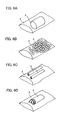
- Figs. 6A to 6D are perspective views illustrating various shapes of the elastic bodies 3 accommodated in the bag 2.
- the filler 1 including the elastic body 3 is preferably larger in volume than the cavity D under natural circumstances so that the volume of the cavity D in the roller body 5 is reduced as much as possible. Further, it is necessary in a compressed state that the outer diameter of the filler 1 becomes shorter than the inner diameter of the roller body 5 and smaller in volume than the cavity.
- the elastic body 3 may be formed by only one block of a columnar shape in circular cross section or by a number of granular resins.
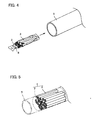
- Fig. 3 is a perspective view of a second step of removing air from the bag 2 in the invention of the method for producing the motorized roller A.
- air is removed from the bag 2 in the second step.
- An evacuator 4 such as an electric vacuum cleaner is expected to be a means of removing air. Air should be removed until the elastic bodies 3 are compressed so that the outer diameter of the filler 1 becomes smaller than the inner diameter of the roller body 5. If and when the bag 2 is evacuated, the inner peripheral surface of its opening mutually sticks fast as the bag 2 is airtight, thereby ensuring that inflow of air from the opening is shut off. That keeps the compressed state of the elastic body 3.
- Fig. 4 is a perspective view of a third step of inserting the bag 2 accommodating the elastic bodies 3 into the cavity D in the roller body 5 in the invention of the method for producing the motorized roller A.
- the filler 1 in which the elastic body has been compressed by removing air from the bag 2 is inserted into the cavity D in the roller body 5 in the third step.
- the outer diameter of the filler 1 is smaller than the inner diameter of the roller body 5, so that friction force does not act on the filler 1 in insertion, and thus, it is not necessary to press the filler 1 into the roller body 5. That facilitates inserting the filler 1 into the roller body 5.
- Fig. 5 is an enlarged perspective view of a principal part of a fourth step of taking air in the bag 2 so as to expand the elastic bodies 3 so that the cavity D is filled with the bag 2 accommodating the elastic bodies 3 in the invention of the method for producing the motorized roller A.
- the filler 1 is inserted up to a predetermined position inside the roller body 5, whereupon air is taken in the bag 2 so as to expand the elastic body 3, so that the filler is filled within the roller body 5.
- Air may be taken in the bag 2 by opening the opening of the bag 2, breaking a part of the bag 2, or releasing of the sealing means 6 such as a fastener or a clip.
- a part of the bag 2 may be broken by making a hole by pricking the bag 2 with a sharp-pointed body such as a needle or by slashing with a cutter such as a knife.
- the above-mentioned embodiments employ the bag 2 as the outer packaging, but may employ one in which the elastic bodies 3 are sandwiched between two sheets with the periphery of the sheets around the elastic bodies 3 adhered after depressurization of space between the two sheets.
- Air within the bag 2 may be removes by pressing the elastic body 3 from outside of the bag 2 so as to compress the elastic body 3, instead of vacuuming up the air as described in the above-mentioned embodiments. According to this method, air in the bag 2 is pushed out by external pressure.
Landscapes
- Engineering & Computer Science (AREA)
- Mechanical Engineering (AREA)
- Buffer Packaging (AREA)
- Rollers For Roller Conveyors For Transfer (AREA)
Applications Claiming Priority (1)
| Application Number | Priority Date | Filing Date | Title |
|---|---|---|---|
| JP2005312325A JP5148826B2 (ja) | 2005-10-27 | 2005-10-27 | モータ内蔵ローラの製造方法 |
Publications (2)
| Publication Number | Publication Date |
|---|---|
| EP1780152A1 true EP1780152A1 (de) | 2007-05-02 |
| EP1780152B1 EP1780152B1 (de) | 2009-08-26 |
Family
ID=37686162
Family Applications (1)
| Application Number | Title | Priority Date | Filing Date |
|---|---|---|---|
| EP06021199A Active EP1780152B1 (de) | 2005-10-27 | 2006-10-10 | Motorisierte Förderrolle und Verfahren zur Herstellung einer solchen Förderrolle |
Country Status (4)
| Country | Link |
|---|---|
| US (1) | US7846081B2 (de) |
| EP (1) | EP1780152B1 (de) |
| JP (1) | JP5148826B2 (de) |
| DE (1) | DE602006008721D1 (de) |
Cited By (2)
| Publication number | Priority date | Publication date | Assignee | Title |
|---|---|---|---|---|
| DE102006054576A1 (de) * | 2006-11-20 | 2008-05-21 | Interroll-Holding Ag | Trommelmotor |
| CN108840069A (zh) * | 2018-06-07 | 2018-11-20 | 吴团结 | 一种木纹砖调头机 |
Families Citing this family (6)
| Publication number | Priority date | Publication date | Assignee | Title |
|---|---|---|---|---|
| US9399556B2 (en) * | 2011-08-11 | 2016-07-26 | Mol Belting Systems, Inc. | End lid design and removal tool |
| TWI725989B (zh) * | 2015-09-18 | 2021-05-01 | 法商維蘇威法國公司 | 用於在高溫使用的輸送機滾輪總成及其製造方法 |
| US20210097968A1 (en) | 2019-09-27 | 2021-04-01 | Dematic Corp. | Sound attenuation for material handling systems |
| US11891252B1 (en) | 2023-01-03 | 2024-02-06 | Dematic Corp. | Sound attenuated conveyor roller assembly |
| US12473151B2 (en) | 2023-07-19 | 2025-11-18 | Intelligrated Headquarters, Llc | Reinforcement to reduce noise and improve flexural strength for metal rollers |
| EP4495031A1 (de) * | 2023-07-19 | 2025-01-22 | Intelligrated Headquarters LLC | Verstärkung zur geräuschminderung und biegefestigkeitsverbesserung für metallwalzen |
Citations (3)
| Publication number | Priority date | Publication date | Assignee | Title |
|---|---|---|---|---|
| US5893821A (en) * | 1996-08-02 | 1999-04-13 | Bridgestone Corporation | Roller for electrophotographic apparatus |
| DE20003777U1 (de) * | 2000-03-01 | 2000-12-21 | Otolski, Johann, 21481 Lauenburg | Rolle |
| JP2003054732A (ja) * | 2001-08-09 | 2003-02-26 | Ito Denki Kk | 搬送用ローラコンベヤのローラ内の結露防止構造 |
Family Cites Families (5)
| Publication number | Priority date | Publication date | Assignee | Title |
|---|---|---|---|---|
| JPS5223079U (de) * | 1975-08-06 | 1977-02-18 | ||
| JPS60256640A (ja) * | 1984-05-31 | 1985-12-18 | Toyo Tire & Rubber Co Ltd | 薄肉円筒体の回転振動防止装置 |
| JPH0619377A (ja) * | 1992-06-29 | 1994-01-28 | Canon Inc | 電子写真感光ドラムおよびそれを用いた電子写真用プロセスカートリッジ並びに電子写真装置 |
| JP3600860B2 (ja) * | 2000-11-22 | 2004-12-15 | 伊東電機株式会社 | モータ内蔵ローラ及びモータ内蔵ローラ用のユニット |
| JP4429648B2 (ja) * | 2003-07-17 | 2010-03-10 | 株式会社リコー | 電子写真感光体及びその製造方法、並びにその電子写真感光体を搭載した画像形成装置 |
-
2005
- 2005-10-27 JP JP2005312325A patent/JP5148826B2/ja not_active Expired - Lifetime
-
2006
- 2006-10-10 EP EP06021199A patent/EP1780152B1/de active Active
- 2006-10-10 DE DE602006008721T patent/DE602006008721D1/de active Active
- 2006-10-18 US US11/583,400 patent/US7846081B2/en active Active
Patent Citations (3)
| Publication number | Priority date | Publication date | Assignee | Title |
|---|---|---|---|---|
| US5893821A (en) * | 1996-08-02 | 1999-04-13 | Bridgestone Corporation | Roller for electrophotographic apparatus |
| DE20003777U1 (de) * | 2000-03-01 | 2000-12-21 | Otolski, Johann, 21481 Lauenburg | Rolle |
| JP2003054732A (ja) * | 2001-08-09 | 2003-02-26 | Ito Denki Kk | 搬送用ローラコンベヤのローラ内の結露防止構造 |
Cited By (3)
| Publication number | Priority date | Publication date | Assignee | Title |
|---|---|---|---|---|
| DE102006054576A1 (de) * | 2006-11-20 | 2008-05-21 | Interroll-Holding Ag | Trommelmotor |
| CN108840069A (zh) * | 2018-06-07 | 2018-11-20 | 吴团结 | 一种木纹砖调头机 |
| CN108840069B (zh) * | 2018-06-07 | 2020-04-07 | 晋江新建兴机械设备有限公司 | 一种木纹砖调头机 |
Also Published As
| Publication number | Publication date |
|---|---|
| JP5148826B2 (ja) | 2013-02-20 |
| US7846081B2 (en) | 2010-12-07 |
| JP2007119155A (ja) | 2007-05-17 |
| DE602006008721D1 (de) | 2009-10-08 |
| US20070099781A1 (en) | 2007-05-03 |
| EP1780152B1 (de) | 2009-08-26 |
Similar Documents
| Publication | Publication Date | Title |
|---|---|---|
| US7846081B2 (en) | Method for producing motorized roller and motorized roller produced by the method | |
| US11492164B2 (en) | Liquid capture apparatus for use with a vacuum sealer | |
| US7770353B2 (en) | Method of sealing an attic access opening and an insulated attic access over | |
| US4160449A (en) | Earplug | |
| EP1647758A3 (de) | Vakuumisolationspaneel | |
| EP1903271B1 (de) | Gasapsorptionsvorrichtung, vakuumwärmeschutz mit der gasapsorptionsvorrichtung und verfahren zur herstellung eines vakuumwärmeschutzes | |
| KR101318725B1 (ko) | 폐기물 수용 장치용 패키지 장치 및 폐기물 수용 장치 | |
| CA2567842A1 (en) | A method and a device for expanding a body under overpressure | |
| EP2538125A3 (de) | Vakuumwärmeisolationsmaterial, Wärmeisolationsbox mit Vakuumwärmeisolationsmaterial, Kühlschrank, Kühl-/Klimaanlage, Wassererhitzer, Geräte und Herstellungsverfahren von Vakuumwärmeisolationsmaterial | |
| EP1710874A3 (de) | Anordnung zur Befestigung eines Kabelbaumes | |
| US6464229B1 (en) | Method and apparatus for sealing a space | |
| EP1724163A3 (de) | Sitzgurtstraffer, Sitzgurtvorrichtung und Fahrzeug mit einer Sitzgurtvorrichtung | |
| JP2018061930A (ja) | シュレッダ | |
| CN108722888B (zh) | 用于电脑配件的检测装置 | |
| JP2005514287A (ja) | 飲用容器と飲用ストローとの間を密閉する装置及び方法 | |
| JP2005514287A6 (ja) | 飲用容器と飲用ストローとの間を密閉する装置及び方法 | |
| FR2931996A1 (fr) | Commande de sonnette compact a grande stabilite mecanique et a protection elevee contre les intemperies et le vandalisme | |
| WO2004016680A3 (en) | Method of producing a hydraulic binder or thermoplastic containing product | |
| US20180156579A1 (en) | Collapsible Target Bag | |
| GB2153327A (en) | Method of packaging a mattress and a packed mattress | |
| CN223499897U (zh) | 一种吸附效果好的冰箱除味剂盒 | |
| JP7640230B2 (ja) | 吸遮音構造の製造方法 | |
| JP2005207556A (ja) | 断熱材の整形体およびその製造方法 | |
| JPH11181909A (ja) | 隙間充填材 | |
| JP3238938U (ja) | 自動車のための音響的に有効な部品 |
Legal Events
| Date | Code | Title | Description |
|---|---|---|---|
| PUAI | Public reference made under article 153(3) epc to a published international application that has entered the european phase |
Free format text: ORIGINAL CODE: 0009012 |
|
| AK | Designated contracting states |
Kind code of ref document: A1 Designated state(s): AT BE BG CH CY CZ DE DK EE ES FI FR GB GR HU IE IS IT LI LT LU LV MC NL PL PT RO SE SI SK TR |
|
| AX | Request for extension of the european patent |
Extension state: AL BA HR MK YU |
|
| AKX | Designation fees paid | ||
| 17P | Request for examination filed |
Effective date: 20070317 |
|
| RBV | Designated contracting states (corrected) |
Designated state(s): DE FR GB |
|
| 17Q | First examination report despatched |
Effective date: 20080218 |
|
| GRAP | Despatch of communication of intention to grant a patent |
Free format text: ORIGINAL CODE: EPIDOSNIGR1 |
|
| GRAS | Grant fee paid |
Free format text: ORIGINAL CODE: EPIDOSNIGR3 |
|
| GRAA | (expected) grant |
Free format text: ORIGINAL CODE: 0009210 |
|
| AK | Designated contracting states |
Kind code of ref document: B1 Designated state(s): DE FR GB |
|
| REG | Reference to a national code |
Ref country code: GB Ref legal event code: FG4D |
|
| REF | Corresponds to: |
Ref document number: 602006008721 Country of ref document: DE Date of ref document: 20091008 Kind code of ref document: P |
|
| PLBE | No opposition filed within time limit |
Free format text: ORIGINAL CODE: 0009261 |
|
| STAA | Information on the status of an ep patent application or granted ep patent |
Free format text: STATUS: NO OPPOSITION FILED WITHIN TIME LIMIT |
|
| 26N | No opposition filed |
Effective date: 20100527 |
|
| REG | Reference to a national code |
Ref country code: FR Ref legal event code: PLFP Year of fee payment: 10 |
|
| REG | Reference to a national code |
Ref country code: FR Ref legal event code: PLFP Year of fee payment: 11 |
|
| REG | Reference to a national code |
Ref country code: FR Ref legal event code: PLFP Year of fee payment: 12 |
|
| REG | Reference to a national code |
Ref country code: FR Ref legal event code: PLFP Year of fee payment: 13 |
|
| PGFP | Annual fee paid to national office [announced via postgrant information from national office to epo] |
Ref country code: GB Payment date: 20250930 Year of fee payment: 20 |
|
| PGFP | Annual fee paid to national office [announced via postgrant information from national office to epo] |
Ref country code: FR Payment date: 20250930 Year of fee payment: 20 |
|
| PGFP | Annual fee paid to national office [announced via postgrant information from national office to epo] |
Ref country code: DE Payment date: 20250930 Year of fee payment: 20 |