EP1780160B1 - Anormalzustandsbremssystem für aufzug - Google Patents
Anormalzustandsbremssystem für aufzug Download PDFInfo
- Publication number
- EP1780160B1 EP1780160B1 EP04730711A EP04730711A EP1780160B1 EP 1780160 B1 EP1780160 B1 EP 1780160B1 EP 04730711 A EP04730711 A EP 04730711A EP 04730711 A EP04730711 A EP 04730711A EP 1780160 B1 EP1780160 B1 EP 1780160B1
- Authority
- EP
- European Patent Office
- Prior art keywords
- car
- hoistway
- speed
- end portion
- rope
- Prior art date
- Legal status (The legal status is an assumption and is not a legal conclusion. Google has not performed a legal analysis and makes no representation as to the accuracy of the status listed.)
- Expired - Lifetime
Links
Images




Classifications
-
- B—PERFORMING OPERATIONS; TRANSPORTING
- B66—HOISTING; LIFTING; HAULING
- B66B—ELEVATORS; ESCALATORS OR MOVING WALKWAYS
- B66B5/00—Applications of checking, fault-correcting, or safety devices in elevators
- B66B5/02—Applications of checking, fault-correcting, or safety devices in elevators responsive to abnormal operating conditions
- B66B5/16—Braking or catch devices operating between cars, cages, or skips and fixed guide elements or surfaces in hoistway or well
- B66B5/18—Braking or catch devices operating between cars, cages, or skips and fixed guide elements or surfaces in hoistway or well and applying frictional retarding forces
- B66B5/22—Braking or catch devices operating between cars, cages, or skips and fixed guide elements or surfaces in hoistway or well and applying frictional retarding forces by means of linearly-movable wedges
-
- B—PERFORMING OPERATIONS; TRANSPORTING
- B66—HOISTING; LIFTING; HAULING
- B66B—ELEVATORS; ESCALATORS OR MOVING WALKWAYS
- B66B5/00—Applications of checking, fault-correcting, or safety devices in elevators
- B66B5/02—Applications of checking, fault-correcting, or safety devices in elevators responsive to abnormal operating conditions
- B66B5/04—Applications of checking, fault-correcting, or safety devices in elevators responsive to abnormal operating conditions for detecting excessive speed
- B66B5/048—Testing of overspeed governor
-
- B—PERFORMING OPERATIONS; TRANSPORTING
- B66—HOISTING; LIFTING; HAULING
- B66B—ELEVATORS; ESCALATORS OR MOVING WALKWAYS
- B66B5/00—Applications of checking, fault-correcting, or safety devices in elevators
- B66B5/02—Applications of checking, fault-correcting, or safety devices in elevators responsive to abnormal operating conditions
- B66B5/04—Applications of checking, fault-correcting, or safety devices in elevators responsive to abnormal operating conditions for detecting excessive speed
- B66B5/06—Applications of checking, fault-correcting, or safety devices in elevators responsive to abnormal operating conditions for detecting excessive speed electrical
Definitions
- the present invention relates to an emergency braking system for an elevator, which brakes a car when the speed of the car becomes abnormal.
- JP-A 08-324907 As a conventional method of testing the operation of a governor of an elevator, in JP-A 08-324907 , there has been proposed a method of operating the governor by rotating a governor sheave while lifting a governor rope above the governor sheave.
- an electric drill is pressed against the governor sheave, and the governor sheave is rotated by the rotation force of the electric drill.
- a tachometer is pressed against the governor sheave in advance to measure the rotational speed of the governor sheave. In this way, the governor is forcibly operated, and the rotational speed of the governor sheave when the governor is operated is checked by the tachometer.
- JP-A 2001-354372 discloses an elevator apparatus with which the speed of a car at which a safety device is activated is made progressively lower in the vicinity of the terminal end portion of a hoistway, thereby shortening the braking distance upon emergency stop in the vicinity of the terminal end portion of the hoistway. Accordingly, the vertical length of the hoistway can be reduced.
- the speed of the car at which the safety device is activated varies according to the position of the car, so the operation test on the governor must be performed while changing the position of the car.
- Document US 2004/0079591 A1 relates to a safety device for monitoring movement, which has a distance determination unit, a speed determination unit and an intelligent comparator device.
- the comparator device comprises a memory for storing a maximum admissible speed and at least one reference position. When an intermediate speed is exceeded, a triggering unit emits an electronic signal in order to trigger a braking device.
- the present invention has been made with a view toward solving the above mentioned problems, and therefore it is an object of the invention to provide an emergency braking system for an elevator with which an operation test on a braking portion for braking a car can be easily performed with accuracy.
- an emergency braking system for an elevator includes:
- an emergency braking system for an elevator comprises
- Fig. 1 is a structural view schematically showing an elevator apparatus according to Embodiment 1 of the present invention.
- a pair of car guide rails 2 are provided in a hoistway 1.
- a car 3 is raised and lowered in the hoistway 1 while being guided by the car guide rails 2.
- a hoisting machine 4 that is a drive device for raising and lowering the car 3 and a counterweight 6.
- a main rope 5 is wound around a drive sheave 4a of the hoisting machine 4.
- the car 3 and the counterweight 6 are suspended in the hoistway 1 by the main rope 5.
- the hoisting machine 4 is provided with a brake device (not shown) that is a braking portion for braking the rotation of the drive sheave 4a.
- a safety device (braking portion) 7 for braking the car 3 with respect to the car guide rails 2 is mounted in the car 3 so as to be opposed to the car guide rails 2.
- the safety device 7 is arranged below the car 3. Emergency braking is applied on the car 3 upon activation of the safety device 7.
- a rotatable governor sheave 8 is provided at an upper end portion of the hoistway 1. Wound around the governor sheave 8 is a governor rope 9 that moves in synchronism with the raising and lowering of the car 3. Both end portions of the governor rope 9 are connected to the safety device 7. Provided at a lower end portion of the hoistway 1 is a tension pulley 10 around which the governor rope 9 is wound.
- the governor sheave 8 is provided with an encoder 11 as a detection portion for detecting the position and speed of the car 3. Further, in the hoistway 1, there is provided an emergency braking system control device 12 (hereinafter simply refereed to as the "control device 12") that is a control portion for controlling the operation of the emergency braking system for an elevator.
- the encoder 11 is electrically connected to the control device 12.
- the position and speed of the car 3 are obtained based on a measurement signal from the encoder 11.
- the position of the car 3 is obtained based on the measurement signal from the encoder 11, and the speed of the car 3 is obtained by differentiation of the position of the car 3.
- the control device 12 outputs an activation signal that is an electrical signal when the speed of the car 3 becomes abnormal.
- the control portion 12 has a processing portion (computer) 13 for determining the presence/absence of an abnormality in the speed of the car 3, and an I/O port 14 as an input/output portion for the inputting of the measurement signal from the encoder 11 and for the outputting of the results of computation by the processing portion 13.
- the activation signal as the electrical signal is outputted from the I/Oport 14 when the processing portion 13 determines that there is an abnormality in the speed of the car 3.
- a rope catching device (rope restraining device) 15 is provided in the vicinity of the governor sheave 8 as a braking portion for restraining the governor rope 9. Further, acondenser (not shown) is electrically connected to the rope catching device 15. Electric charge for supplying electric power for activating the rope catching device 15 is previously stored in the condenser.
- the control device 12 selectively outputs an activation signal to a brake device of the hoisting machine 4 and to the rope catching device 15.
- the brake device of the hoisting machine 4 is activated when power supply is stopped upon input of the activation signal from the control device 12. Braking is applied to the drive sheave 4a upon the activation of the brake device.
- the rope catching device 15 is activated when supplied with an activating electric power from the condenser upon the input of the activation signal from the control device 12.
- the governor rope 9 is restrained upon the activation of the rope catching device 15.
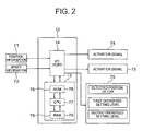
- Fig. 2 is a block diagram showing the control device 12 of Fig. 1 .
- a measurement signal from the encoder 11 is constantly inputted to the I/O port 14 as position information 71 and speed information 72 on the car 3.
- an activation signal 73 and an activation signal 74 can be selectively outputted from the I/O port 14 to the brake device of the hoisting machine 4 and to the rope catching device 15, respectively.
- a display 75 as a display portion for displaying specific computation results from the processing portion 13 is electrically connected to the I/O port 14.
- the processing portion 13 has a storage portion (memory) 76 in which car speed abnormality determination references (set data) serving as the references in detecting the presence/absence of an abnormality in the speed of the car 3 are stored in advance, and a computing portion (CPU) 77 that detects the presence/absence of an abnormality in the speed of the car 3 based on information from each of the encoder 11 and the storage portion 76.
- the storage portion. 76 has a ROM 78 and a RAM 79.
- the car speed abnormality determination references are stored in the ROM 78.
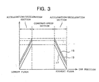
- Fig. 3 is a graph showing the car speed abnormality determination references stored in the storage portion 13 of Fig. 2 .
- a hoisting zone in which the car 3 is raised and lowered between the highest floor (one terminal end portion) and the lowest floor (the other terminal end portion).
- acceleration/deceleration zones respectively adjoining the highest and lowest floors and in which the car 3 is accelerated/decelerated during normal operation, and a constant-speed zone located between the two acceleration/deceleration zones and in which the car 3 is moved at a constant speed (rated speed).
- a normal speed setting level (normal speed pattern) 17 as the speed of the car 3 during normal operation a first overspeed setting level (first overspeed pattern) 18 lager in value than the normal speed setting level 17, and a second overspeed setting level (second overspeed pattern) 19 larger in value than the first overspeed setting level 18, are each set in correspondence with the position of the car 3.
- the normal speed setting level 17, the first overspeed setting level 18, and the second overspeed setting level 19 are each set such that its value is constant in the constant-speed zone and becomes progressively smaller toward the highest and lowest floors in the acceleration/deceleration zones. Further, the first overspeed setting level 18 and the second overspeed setting level 19 are set such that they become smaller in value than the rated speed of the car 3 on the sides closer to the terminal end portions of the acceleration/deceleration zones.
- the normal speed setting level 17, the first overspeed setting level 18, and the second overspeed setting level 19 are stored as the car speed abnormality determination references in correspondence with the position of the car 3.
- the computing portion 77 When the speed of the car 3 thus obtained exceeds the first overspeed setting level 18, the computing portion 77 outputs the activation signal 73 to the brake device of the hoisting machine 4; when the speed of the car 3 exceeds the second overspeed setting level 19, the computing portion 77 outputs the activation signal 74 to the rope catching device 15. The outputting of the activation signal 73 to the brake device of the hoisting machine 4 is maintained while the activation signal 74 is being outputted. It should be noted that when the rope catching device 15 is to be deactivated and returned to the normal state, the computing portion 77 outputs to the rope catching device 15 a return signal that is an electrical signal. When inputted with the return signal, the rope catching device 15 is returned upon supply of return electric power from the condenser.
- the display 75 displays the detected position of the car 3 obtained based on information from the encoder 11, the value of the first overspeed setting level 18 at the detected position of the car 3, and the value of the second overspeed setting level 19 at the detected position of the car 3.
- each safety device 7 has: a wedge 20 as a braking member that can be brought into and out of contact with the car guide rail 2; a pivot lever 21 as a link mechanism for displacing the wedge 20 relative to the car 3 through displacement of the car 3 relative to the governor rope 9; and a gripper metal 22 as a guide portion for guiding the wedge 20, which is displaced by the pivot lever 21, into contact with the car guide rail 2.
- Each wedge 20 is arranged below the gripper metal 22. Each wedge 20 is affixed with a friction material 23 that contacts the car guide rail 2. Fixed to the lower end portion of each wedge 20 is a mounting portion 24 that extends downwards from the wedge 20.
- a horizontally extending connecting shaft 25 is rotatably provided to the lower end portion of the car 3.
- One end of each pivot lever 21 is fixed to either end of the connecting shaft 25 ( Fig. 5 ).
- an elongated hole 26 is provided at the other end portion of each pivot lever 21 extending in the longitudinal direction of the pivot lever 21.
- Each pivot lever 21 is provided to the lower end portion of the car 3 such that the elongated hole 26 is arranged below the gripper metal 22.
- Each mounting portion 24 is slidably fitted in each elongate hole 26.
- the lifting bar 27 extends in the vertical direction.
- each pivot lever 21 is pivoted about the axis of the connecting shaft 25.
- Each wedge 20 is displaced toward the gripper metal 22 as the other end portion of the pivot lever 21 is pivoted upwards.
- the gripper metal 22 is arranged in a recess 29 provided at the lower end portion of the car 3. Further, the gripper metal 22 has a sliding member 30 and a pressing member 31 that are arranged so as to sandwich the car guide rail 2 therebetween. The sliding member 30 and the pressing member 31 are supported by a support member 32 fixed in the recess 29.
- the sliding member 30 is provided with an inclined portion 33 that slidably holds the wedge 20.
- the inclined portion 33 is inclined with respect to the car guide rail 2 such that its distance to the car guide rail 2 becomes smaller toward its upper portion. It should be noted that the sliding member 30 is fixed to the support member 32.
- the pressing member 31 is supported on the support member 32 through support springs 34 as elastic members.
- the pressing member 31 is affixed with a friction material 35 that contacts the car guide rail 2.
- the wedge 20 is displaced into contact with the car guide rail 2 and pushed in between the car guide rail 2 and the sliding member 30.
- the car 3 is displaced to the left as seen in the figure as the wedge 20 is pushed in between the car guide rail 2 and the sliding member 30.
- the wedge 20 and the pressing member 31 are displaced toward each other so as to hold the car guide rail 2 therebetween.
- a braking force acting on the car 3 is generated as the wedge 20 and the pressing member 31 are pressed against the car guide rail 2.
- a torsion spring (not shown) urging the connecting shaft 25 so as to displace each wedge 20 downwards. The malfunction of each safety device 7 is thus prevented.
- a stopper 36 fixed to the lower end portion of the car 3 is a stopper 36 that regulates the downward pivotal movement of the pivot lever 21. This prevents inadvertent detachment of the wedge 20 from the inclined portion 33.
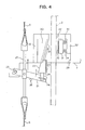
- Fig. 6 is a structural view showing the rope catching device 15 of Fig. 1 .
- the rope catching device 15 is supported on a frame member 41 to which the governor sheave 8 is provided.
- the rope catching device 15 has: a pressing shoe 42 that is a restraining portion displaceable between a restraining position for restraining the governor rope 9 in place and a disengaged position for releasing the restraining of the governor rope 9; an electromagnetic actuator 43 that generates a drive force for displacing the pressing shoe 42 between the restraining position and the disengaged position; and a connecting mechanism portion 44 that connects between the electromagnetic actuator 43 and the pressing shoe 42 and transmits the drive force from the electromagnetic actuator 43 to the pressing shoe 42.
- the mounting member 45 Fixed on top of the frame member 41 is a mounting member 45 to which the electromagnetic actuator 43 is mounted.
- the mounting member 45 has a horizontal portion 46 on which the electromagnetic actuator 43 is placed, and a vertical portion 47 extending upwards from an end portion of the horizontal portion 46.
- the pressing shoe 42 is formed of a friction material having a contact surface opposed to the outer periphery of the governor sheave 8. Further, when in the restraining position, the pressing shoe 42 is pressed against the governor sheave 8 through the governor rope 9, and when in the disengaged position, the pressing shoe 42 is moved away from the governor rope 9.
- the electromagnetic actuator 43 is activated upon input of the activation signal 74 from the control device 12 and displaces the pressing shoe 42 into the restraining position. Further, the electromagnetic actuator 43 is returned into position upon input of the return signal from the control device 12, whereby the pressing shoe 42 is displaced into the disengaged position.
- the connecting mechanism portion 44 has a movable rod 48 that is caused to reciprocate through the drive of the electromagnetic actuator 43, and a displacement lever 49 provided with the pressing shoe 42 and causing the pressing shoe 42 to displace between the restraining position and the disengaged position due to the reciprocating motion of the movable rod 48.
- One end portion (lower end portion) of the displacement lever 49 is pivotably attached to the frame member 41, and the other end portion (upper end portion) of the displacement lever 49 is slidably attached to the movable rod 48. Further, the pressing shoe 42 is pivotably attached to the intermediate portion of the displacement lever 49. As the movable rod 48 advances, the displacement lever 49 is pivoted so as to displace the pressing shoe 42 into the disengaged position, and as the movable rod 48 retracts, the displacement lever 49 is pivoted so as to displace the pressing shoe 42 into the restraining position.
- the movable rod 48 extends horizontally from the electromagnetic actuator 43 and slidably penetrates the vertical portion 47. Further, a first spring connecting portion 51 is fixed to the distal end portion of the movable rod 48. Connected between the upper end portion of the displacement lever 49 and the first spring connecting portion 51 is a compression spring 52 serving as an elastic member for pressing the pressing shoe 42 onto the governor sheave 8 side when the pressing shoe 42 is in the restraining position.
- a second spring connecting portion 53 is fixed between the electromagnetic actuator 43 of the movable rod 48 and the vertical portion 47.
- an adjusting spring 54 serving as an elastic member for mitigating the load on the electromagnetic actuator 43.
- the adjusting spring 54 is adjusted to urge the movable rod 48 being reciprocated in the direction opposite to the direction of the urging by the compression spring 52. This prevents a large difference from developing between the magnitude of the load on the electromagnetic actuator 43 when the pressing shoe 42 is in the restraining position and the magnitude of the load on the electromagnetic actuator 43 when the pressing shoe 42 is in the disengaged position.
- a stopper 55 Fixed between the upper end portion of the displacement lever 49 of the movable rod 48 and the vertical portion 47 is a stopper 55 for regulating the range within which the upper end portion of the displacement lever 49 is allowed to slide. As the movable rod 48 advances, the stopper 55 causes the displacement lever 49 to pivot so as to displace the pressing shoe 42 into the disengaged position, while pressing on the other end portion of the displacement lever 49.
- Fig. 7 is a sectional view showing the electromagnetic actuator 43 of Fig. 6 .
- the electromagnetic actuator 43 has a movable iron core (movable portion) 56 fixed to the rear end portion of the movable rod 48, and a driver portion 57 for displacing the movable iron core 56.
- the iron core 56 is displaceable between an activation position where the pressing shoe 42 restrains the governor rope 9 in the restraining position, and a release position where the pressing shoe 42 is displaced into the disengaged position to release the restraining of the governor rope 9.
- the driver portion 57 has: a stationary iron core 61 including a pair of regulating portions 58, 59 regulating the displacement of the movable iron core 56, and a side wall portion 60 connecting the regulating portions 58, 59 to each other; a first coil 62 accommodated in the stationary iron core 61 and serving as a release coil which, when energized, displaces the movable iron core 56 into contact with one regulating portion, the regulating portion 58; a second coil 63 accommodated in the stationary iron core 61 and serving as an activation coil which, when energized, displaces the movable iron core 56 into contact with the other regulating portion, the regulating portion 59; and an annular permanent magnet 64 arranged between the first coil 62 and the second coil 63.
- the one regulating portion 58 is provided with a through-hole 65 through which the movable rod 48 is passed.
- the movable iron core 56 When in the release position, the movable iron core 56 is in abutment with the one regulating portion 58, and when in the release position, the movable iron core 56 is in abutment with the other regulating portion 59.
- the first coil 62 and the second coil 63 are annular electromagnetic coils surrounding the movable iron core 56. Further, the first coil 62 is arranged between the permanent magnet 64 and the one regulating portion 58, and the second coil 63 is arranged between the permanent magnet 64 and the other regulating portion 59.
- Electric power stored in the condenser is supplied to the second coil 63 as the activation signal 74 from the I/O port 13 ( Fig. 1 ) is inputted to the electromagnetic actuator 43. Further, when supplied with electric power from the condenser, the second coil 63 generates a magnetic flux acting against the force for retaining the abutment of the movable iron core 56 with the one regulating portion 58. Further, when the return signal from the processing portion 14 is inputted to the electromagnetic actuator 43, electric power stored in the condenser is supplied to the first coil 62. Further, when supplied with electric power from the condenser, the first coil 62 generates a magnetic flux acting against the force for retaining the abutment of the movable iron core 56 with the other regulating portion 59.
- the activation signal 73 is outputted from the control device 12 to the brake device of the hoisting machine 4, thus activating the brake device. Braking is thus applied to the drive sheave 4a to brake the car 3.
- the activation signal 74 is outputted to the rope catching device 15 from the control device 12. Accordingly, electric power stored in the condenser is instantaneously supplied to the second coil 63. As a result, the movable rod 48 is retracted, whereby the displacement lever 49 is pivoted counterclockwise as seen in Fig. 5 . Then, the pressing shoe 42 is pressed against the governor sheave 8 through the governor rope 9 and displaced into the restraining position. As a result, the governor rope is restrained by the rope catching device 15. In the state where the pressing shoe 42 has been displaced into the restraining position, the movable iron core 56 is retained in abutment with the other regulating portion 59.
- the governor rope 9 Due to the restraining of the governor rope 9 by the rope catching device 15, the governor rope 9 is displaced upwards relative to the car 3 that is descending at an abnormal speed, whereby the wedge 20 is displaced toward the gripper metal 22, that is, in the upward direction. At this time, the wedge 20 is displaced into contact with the car guide rail 2 while sliding on the inclined portion 33. Then, the wedge 20 and the pressing member 31 are brought into contact with and pressed against the car guide rail 2. Upon contacting the car guide rail 2, the wedge 20 is displaced further upwards to be wedged between the car guide rail 2 and the sliding member 30. As a result, a large friction force is generated between each of the wedge 20 and pressing member 31 and the car guide rail 2, thereby braking the car 3.
- the detected position of the car 3 detected by the encoder 11 and the respective values of the first overspeed setting level 18 and second overspeed setting level 19 at the detected position are displayed on the display 75. Since it is measured while lifting up the governor rope 9 above the governor sheave 8, the detected position of the car 3 displayed on the display 75 differs from the actual position of the car 3 in most cases.
- the rotational speed of the governor sheave 8 is increased while looking at the indication on the display 75 and the tachometer, and when the rotational speed of the governor sheave 8 corresponding to the detected position of the car 3 exceeds the value of the first overspeed setting level 18, the activation signal 73 is outputted from the control device 12 to the brake device of the hoisting machine 4.
- the presence/absence of an abnormality in the operation of the brake device of the hoisting device 4 can be checked through comparison between the value of the first overspeed setting level 18 displayed on the display 75 and the value of the rotational speed of the governor rope 8 as measured by the tachometer.
- the braking device of the hoisting machine 4 is determined to be operating normally when the difference between the value of the first overspeed setting level 18 and the value of the rotational speed of the governor sheave 8 as measured by the tachometer falls within a permissible range, and the brake device of the hoisting machine 4 is determined to be operating abnormally when the above difference deviates from the permissible range.
- the rotational speed of the governor sheave 8 is further increased, and when the rotational speed of the governor sheave 8 corresponding to the detected position of the car 3 exceeds the value of the second overspeed setting level 19, the activation signal 74 is outputted from the control device 12 to the rope catching device 15. At this time, the presence/absence of an abnormality in the operation of the rope catching device 15 is checked through comparison between the value of the second overspeed setting level 19 displayed on the display 75 and the value of the rotational speed of the governor rope 8 as measured by the tachometer.
- the rope catching device 15 is determined to be operating normally when the difference between the value of the second overspeed setting level 19 and the value of the rotational speed of the governor sheave 8 as measured by the tachometer falls within a permissible range, and the rope catching device 15 is determined to be operating abnormally when the above difference deviates from the permissible range.
- the detected position of the car 3 as detected by the encoder 11 and the respective values of the first overspeed setting level 18 and second overspeed setting level 19 at the detected position are displayed on the display 75. Accordingly, even in a case where the first overspeed setting level 18 and the second overspeed setting level 19 are set so as to change continuously according to the position of the car 3, the values of the respective setting levels when the brake device of the hoisting machine 4 and the rope catching device 15 operate during the operation test on the system can be easily and accurately ascertained.
- the timings at which the brake device of the hoisting machine 4 and the rope catching device 15 operate can be easily and accurately ascertained, whereby the operation test can be easily and accurately performed on the brake device of the hoisting machine 4 and on the rope catching device 15.
- Fig. 8 is a block diagram showing the control device 12 of an emergency braking system for an elevator according to Embodiment 2 of the present invention.
- a selector switch 82 electrically connected to the I/O port 14 is a selector switch 82 capable of switching between a normal mode in which the position information 71 from the encoder 11 can be inputted to the I/O port 14 and a test mode in which desired setting information 81 can be inputted to the I/O port 14 as the position information on the car 3.
- the position information 71 from the encoder 11 is constantly inputted. Further, in the normal mode, the detected position of the car 3 obtained from the position information 71, and the respective values of the first overspeed setting level 18 and second overspeed setting level 19 at the detected position are displayed on the display 75. Accordingly, when the governor sheave 8 is rotated, the values displayed on the display 75 change in accordance with the rotation.
- Embodiment 2 In the test mode, the set position of the car 3 obtained from the setting information 81 inputted to the I/O port 14, and the respective values of the first overspeed setting level 18 and second overspeed setting level 19 at the set position are displayed on the display 75.
- the values displayed on the display 75 thus do not change but remain fixed even when the governor sheave 8 is rotated. Otherwise, the construction and operation of Embodiment 2 are the same as those of Embodiment 1.
- the setting information 81 corresponding to the positions where the brake device of the hoisting machine 4 and the rope catching device 15 are to be activated is inputted to the I/O port 14, and the setting information 81 is stored in the storage portion 76.
- the governor shave 8 is rotated by the turning gear in the same manner as in Embodiment 1, and the brake device of the hoisting machine 4 and the rope catching device 15 are activated in the stated order while increasing the rotation speed of the governor sheave 8.
- the brake device of the hoistingmachine 4 it is checked whether or not the difference in value between the rotation speed of the governor sheave 8 as measured by the tachometer and the first overspeed setting level 18 falls within the permissible range.
- the rope catching device 15 is activated, it is checked whether or not the difference in value between the rotation speed of the governor sheave 8 as measured by the tachometer and the second overspeed setting level 18 falls within the permissible range.
- the mode of the control device 12 is switched from the test mode to the normal mode by means of the selector switch 82.
- the control device 12 can be switched between the normal mode, in which the position of the car 3 can be found based on the position information 71 from the encoder 11, and the test mode, in which the position of the car 3 can be found based on the desired setting information 81 externally inputted. Accordingly, by switching the control device 12 to the test mode, the position of the car 3 can be freely set in the control device 12 irrespective of the rotation of the governor shave 8. This facilitates the setting of the position of the car 3, and the respective operations of the brake device of the hoisting machine 4 and of the rope catching device 15 can be easily tested.
- Fig. 9 is an explanatory diagram showing a method of controlling the control device 12 of an emergency braking system for an elevator according to Embodiment 3 of the present invention.
- the control device 12 can be switched between a normal mode, in which the car 3 is run so that the speed of the car 3 becomes the normal speed setting level 17, and a test mode, in which the car 3 is run at a sampling speed V OS (x) that is the same as the value of the first overspeed setting level 18 at a sampling position spaced apart by a predetermined distance x from the terminal end portion of the hoistway 1.
- the control device 12 causes the activation signal 73 to be forcibly outputted from the I/O port 14 to the brake device of the hoisting machine 4.
- the brake device is activated, so the car 3 is braked to stop.
- the sampling position is set within the acceleration/deceleration zone.
- the display 75 displays a speed V BOS of the car 3 at a simulated terminal end position spaced apart by the distance x from the intermediate position M of the hoistway 1.
- the construction and operation of Embodiment 3 are the same as those of Embodiment 1.
- the brake device is activated when the car 3 reaches the intermediate position M of the hoistway 1.
- the drive sheave 4a is thus braked to stop the car 3. That is, the behaviors of the car 3 when the car 3 is braked by the brake device at the sampling position are simulated and reproduced at the intermediate portion of the hoistway 1.
- the speed V BOS of the car 3 at the simulated terminal end position is displayed on the display 75.
- switching can be made between the normal mode, in which the car 3 is run at a speed at which the car 3 runs during the normal operation, and the test mode, in which the car 3 is run at the speed V OS (x) that is the same as the value of the first overspeed setting level 18 at the sampling position spaced apart by the predetermined distance x from the terminal end portion of the hoistway 1.
- the test mode in which the car 3 passes the intermediate position M of the hoistway 1, the activation signal 73 is forcibly outputted from the control device 12 to the brake device of the hoisting machine 4.
- the display 75 displays the speed V BOS of the car 3 at the simulated terminal end position spaced apart by the distance x from the intermediate position M, so the speed of the car 3 when it collides against the buffer can be easily and accurately ascertained, whereby the operation test on the brake device of the hoisting machine 4 can be performed with greater ease and accuracy.
- the car 3 is run at the same speed as the value of the first overspeed setting level 18 at the sampling position, and the brake device of the hoisting machine 4 is activated at the intermediate position M of the hoistway 1.
- the car 3 is run at a sampling speed V TR (x) that is the same as the value of the second overspeed setting level 19 at the sampling position, and when the car 3 passes the intermediate position M of the hoistway 1, the activation signal 74 is forcibly outputted from the control device 12 to the rope catching device 15 to thereby activate the rope catching device 15.
- the display 75 may display the speed of the car 3 at the simulated terminal end position spaced apart by the distance x from the intermediate position M. Accordingly, the speed of the car 3 when it collides against the buffer can be easily and accurately ascertained, whereby the operation test on the rope catching device 15 can be performed with greater ease and accuracy.
- the display 75 may display the distance that the car 3 travels until it stops through the operation of the rope catching device 15. As a result, an operation test can be easily and accurately performed on the rope catching device 15 as well.
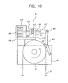
- Fig. 10 is a structural view showing a rope catching device of an emergency braking system for an elevator according to Embodiment 5 of the present invention.
- an electromagnetic actuator 81 is mounted to the mounting member 45.
- the electromagnetic actuator 81 has: a movable portion 82 that is displaceable between an activation position for causing the pressing shoe 42 to restrain the governor rope 9 and a release position for releasing the restraining of the governor rope 9; a compression spring 83 as an urging portion for urging the movable portion 82 toward the activation position; and an electromagnet 84 for displacing the movable portion 82 toward the release position against the urging force of the compression spring 83.
- the electromagnet 84 is mounted on top of the horizontal portion 46.
- the movable portion 82 has a movable plate 85 that is sucked onto the electromagnet 84 upon energizing the electromagnet 84, and a movable rod 86 fixed to the movable plate 85 and slidably penetrating the electromagnet 84 and the vertical portion 47.
- the distal end portion of the movable rod 86 is connected to the upper end portion of the displacement lever 49 through a link 87.
- the link 87 is connected to each of the movable rod 86 and the displacement lever 49.
- a spring connecting portion 88 is fixed to the portion of the movable rod 86 between the electromagnet 84 and the vertical portion 47.
- the compression spring 83 is connected between the spring connecting portion 88 and the vertical portion 47.
- the displacement lever 49 is pivoted due to the reciprocating motion of the movable rod 86. Accordingly, the positional relation between the movable rod 86 and the displacement lever 49 varies due to a difference in displacement between the movable rod 86 and the displacement lever 49.
- the link 87 is connected between the movable rod 86 and the displacement lever 49 in order to permit this variation.
- the electromagnetic actuator 81 is activated upon input of an activation signal from the control device 12.
- the electromagnetic actuator 81 is activated upon stopping the energization of the electromagnet 84.
- the movable portion 82 is retracted for displacement into the activation position. This causes the pressing shoe 42 to be displaced into the restraining position.
- Embodiment 5 is of the same construction as Embodiment 1.
- the return signal is outputted from the control device 12 to the electromagnetic actuator 81, thereby energizing the electromagnet 84. Accordingly, the movable portion 82 is advanced, so the pressing shoe 94 is displaced into the disengaged position. As a result, the restraining of the governor rope 9 is released.
- the operation test can be easily and accurately performed on the brake device of the hoisting machine 4 and on the rope catching device.
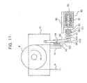
- Fig. 11 is a structural view showing a rope catching device of an emergency braking system for an elevator according to Embodiment 6 of the present invention.
- a fixing member 91 fixed to the lower end portion of the frame member 41 is a fixing member 91 extending downwards from the frame member 41.
- a receiving portion 92 formed of a high friction material is affixed to the fixing member 91.
- the upper end portion of a substantially obtuse V-shaped displacement lever 93 is pivotably connected to the frame member 41.
- a pressing shoe 94 Pivotably provided to the intermediate portion of the displacement lever 93 is a pressing shoe 94 as a pressing member displaceable into and out of contact with the receiving portion 92.
- the pressing shoe 94 is displaceable between a restraining position, where it is pressed against the receiving portion 92 through the governor rope 9 due to the pivotal movement of the displacement lever 93, and a disengaged position where it is moved away from the governor rope 9.
- the portion of the pressing shoe 94 which comes into contact with the governor rope 9 is formed of a high friction material.
- An actuator supporting member 96 having a projection portion 95 is fixed below the frame member 41.
- the electromagnetic actuator 43 of the same construction as that of Embodiment 1 is supported on the actuator supporting member 96.
- a movable rod 97 fixed to the movable iron core 56 extends horizontally from the electromagnetic actuator 43.
- the movable rod 97 slidably penetrates the projection portion 95.
- the lower end portion of the displacement lever 93 is slidably provided to the movable rod 97. Further, fixed to the distal end portion of the movable rod 97 is a stopper 98 for regulating the range within which the lower end portion of the displacement lever 93 is allowed to slide.
- a spring connecting portion 99 is fixed to the portion of the movable rod 97 between the lower end portion of the displacement lever 93 and the projection portion 95.
- a compression spring 100 that is an elastic member for pressing the pressing shoe 94 in the restraining position onto the receiving portion 92 side.
- an adjusting spring 101 that is an elastic member for mitigating the load on the electromagnetic actuator 43.
- the electromagnetic actuator 43 is activated upon input of an activation signal from the control device 12.
- the movable rod 97 is advanced through the activation of the electromagnetic actuator 43 to displace the pressing shoe 94 into the restraining position. Further, the movable rod 97 is retracted upon input of a return signal to the electormagnetic actuator 43. As the movable rod 97 is retracted, the pressing shoe 94 is displaced into the disengaged position.
- Embodiment 6 is of the same construction as Embodiment 1.
- the return signal is outputted from the control device 12, causing the movable rod 97 to retract. Accordingly, the pressing shoe 94 is displaced into the disengaged position, whereby the restraining of the governor rope 9 is released.
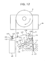
- Fig. 12 is a structural view showing a rope catching device of an emergency braking system for an elevator according to Embodiment 7 of the present invention. Further, Fig. 13 is a structural view showing a state in which the rope catching device of Fig. 12 has been activated.
- a fixing member 111 is fixed in the vicinity of the governor rope 9.
- a receiving portion 112 formed of a high friction material is affixed to a side surface of the fixing member 111.
- a horizontal shaft 113 is fixed in the hoistway 1.
- the horizontal shaft 113 is arranged at substantially the same height as the receiving portion 112.
- One end portion of an elastic expansion member 114 that is capable of expansion and contraction is pivotably provided to the horizontal shaft 113.
- Pivotably provided to the other end portion of the elastic expansion member 114 is a pressing shoe 115 that is displaceable into and out of contact with the receiving portion 112.
- the pressing shoe 115 is displaced between a restraining position ( Fig. 13 ) where the pressing shoe 115 is pressed against the receiving portion 112 through the governor rope 9, and a disengaged position ( Fig. 12 ) where the pressing shoe 115 is moved away from the governor rope 9 to release the restraining of the governor rope 9.
- the elastic expansion member 114 is contracted by the reaction force of the receiving portion 112.
- the length of the elastic expansion member 114 is adjusted such that the pressing shoe 115 is pivoted without its lower end portion abutting the upper surface of the receiving portion 112 and that the elastic expansion member 114 undergoes contraction between the horizontal shaft 113 and the receiving portion 112 when the elastic expansion member 114 is substantially horizontal.
- the elastic expansion member 114 has an expansion rod 116 to which the pressing shoe 115 is provided, and a compression spring 117 for urging the pressing shoe 115 that is in the restraining position onto the receiving portion 112 side.
- the expansion rod 116 has a first connecting portion 118 pivotably provided to the horizontal shaft 113, a second connecting portion 119 pivotably connected to the pressing shoe 115, and an expansion portion 120 connecting between the first and second connecting portions 118, 119.
- the expansion portion 120 has a plurality of slide tubes 121 capable of sliding with respect to each other. Further, the expansion portion 120 can expand and contract as the slide tubes 121 are slid with respect to each other.
- the compression spring 117 is connected between the first and second connecting portions 118, 119. Further, as the compressing spring 117 is displaced so as to bring the first connecting portion 118 and the second connecting portion 119 closer to each other, the compressing spring 117 generates an elastic restoration force acting in the direction in which the elastic expansion member 114 expands.
- the electromagnetic actuator 43 of the same construction as that of Embodiment 1 is disposed in the hoistway 1.
- a movable rod 122 capable of reciprocating with respect to the electromagnetic actuator 43.
- a spring connecting portion 123 is fixed to the distal end portion of the movable rod 122.
- a fastening member 124 is slidably provided to the portion of the movable rod 122 between the spring connecting portion 123 and the electromagnetic actuator 43.
- a connecting spring 125 is connected between the spring connecting portion 123 and the fastening member 124.
- the fastening member 124 and the pressing shoe 115 are connected to each other through a connecting mechanism portion 126.
- the connecting mechanism portion 126 has a first link member 127 and a second link member 128 that are pivotably connected to each other.
- the first link member 127 is supported on a support shaft 129 parallel to the horizontal shaft 113.
- the supported shaft 129 is fixed in position in the hoistway 1.
- the intermediate portion of the first link member 127 is pivotably provided to the support shaft 129.
- one end portion of the first link member 127 is pivotably connected to the fastening member 124, and the other end portion of the first link member 127 is pivotably connected to one end portion of the second link member 128.
- the length of the second link member 128 is smaller than the length of the first link member 127.
- the other end portion of the second link member 128 is pivotably connected to the pressing shoe 115.
- the pressing shoe 115 is pivoted downwards about the horizontal shaft 113 to be displaced into the restraining position. Further, as the movable rod 112 is displaced (retracted) downwards, the pressing shoe 115 is pivoted upwards about the horizontal shaft 113 to be displaced into the disengaged position.
- Embodiment 7 is of the same construction as Embodiment 1.
- the return signal is outputted from the control device 12 to cause the movable rod 122 to retract.
- the pressing shoe 115 is displaced into the disengaged position and thus the restraining of the governor rope 9 is released.
- the operation test can be easily and accurately performed on the brake device of the hoisting machine 4 and on the rope catching device.
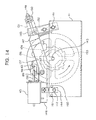
- Fig. 14 is a front view showing a rope catching device of an emergency braking system for an elevator according to Embodiment 8 of the present invention.
- support shafts 141, 142 are fixed to a frame member 41.
- a support portion 143 for the rotation shaft of the governor sheave 8 is provided to the portion of the frame member 41 between the support shaft 141 and the support shaft 142.
- One end portion (lower end portion) of the support link 144, and one end portion (lower end portion) of a displacement lever 145 are pivotably provided to the support shaft 141 and the support shaft 142, respectively.
- a movable base 146 Arranged above the frame member 41 is a movable base 146 displaceable with respect to the frame member 41.
- the movable base 146 is connected to the respective other end portions (upper end portions) of the support link 144 and displacement lever 145.
- the movable base 146 is thus supported on the frame member 41 through the support link 144 and the displacement lever 145.
- the movable base 146 has a movable base main body 147, and a screw bar 148 extending outwards from the movable base main body 147 and slidably penetrated through the upper end portion of the displacement lever 145.
- the upper end portion of the support link 144 is pivotably provided to the movable base main body 147.
- a spring fastening member 150 Mounted to the screw bar 148 is a spring fastening member 150 whose distance from the movable base main body 147 can be adjusted.
- a compression spring 151 as an elastic member fitted to the screw bar 148 is arranged between the upper end portion of the displacement lever 147 and the spring fasteningmember 150.
- the compression spring 151 is compressed between the upper end portion of the displacement lever 147 and the spring fastening member 150.
- the upper end portion of the displacement lever 147 and the spring fastening member 150 are urged so as to move away from each other.
- a pressing shoe 152 as a pressing member is pivotably provided to the intermediate portion of the displacement lever 147.
- the pressing shoe 152 is displaceable between a restraining position where it is pressed against the governor sheave 8 through the governor rope 9, and a disengaged position where it is moved away from the governor rope 9.
- the pressing shoe 152 is displaced between the restraining position and the disengaged position due to the pivotal movement of the displacement lever 147 about the support shaft 141.
- ratchet gear 153 Fixed to the governor sheave 8 is a ratchet gear 153 rotated integrally with the governor sheave 8.
- the ratchet gear 153 has a plurality of tooth portions 154 in its outer peripheral portion.
- a latch supporting shaft 155 is fixed to the movable base main body 147.
- a latch 157 having a claw portion 156 is pivotably provided to the latch supporting shaft 155.
- the latch 157 is displaceable between an engaged position where the claw portion 156 is engaged with the tooth portion 154 of the ratchet gear 153, and a release position where the claw portion 156 is released from engagement with the ratchet gear 153.
- the latch 157 is displaced between the engaged position and the release position as it pivots about the latch supporting shaft 155.
- the latch supporting shaft 155 is arranged at a position lower than the height of the distal end portion of the claw portion 156 when the latch 157 is in the engaged position. Further, the cutting angle of the tooth portions 154 with respect to the rotation direction of the ratchet gear 153 is set such that the trajectory of the claw portion 156 when the latch 157 is pivoted about the latch supporting shaft 155 does not overlap the tooth portions 154. Accordingly, it is possible to reduce the magnitude of the drive force required for the operation of displacing the latch 157 from the engaged position to the release position, that is, the return operation.
- Amovable rod 158 capable of reciprocating with respect to the electromagnetic actuator 43 extends horizontally from the electromagnetic actuator 43.
- the movable rod 158 is horizontally reciprocated through the drive of the electromagnetic actuator 43.
- An elongated hole 163 is provided at the distal end portion of the movable rod 158.
- Fixed to the latch 157 is a latch mounting member 159 slidably fitted in the elongated hole 163. The latch 157 is displaced into the engaged position as the movable rod 158 advances, and is displaced into the release position as the movable rod 158 retracts.
- the movable base main body 147 When the latch 157 is in the release position, the movable base main body 147 is supported in a balanced manner by the support link 144 and the displacement lever 145, and the pressing shoe 152 is displaced into the disengaged position. Further, in the state in which the ratchet gear 153 is being rotated in the direction in which the car 3 is being lowered (in the state in which the ratchet gear 153 is being rotated in the direction C in the figure), when the latch 157 is displaced into the engaged position, due to the rotation force of the ratchet gear 153, the movable base main body 147 is displaced in the direction (leftwards in the figure with respect to the frame member 41) for causing the pressing shoe 152 to be displaced into the restraining position.
- the frame member 41 is provided with a first stopper 160 and a second stopper 161 which regulate the pivotal movement of the support link 144.
- first stopper 160 regulating the pivotal movement of the support link 144
- second stopper 161 regulating the pivotal movement of the support link 144
- the operation test can be easily and accurately performed on the brake device of the hoisting machine 4 and on the rope catching device.
- braking may be applied to an overspeed in the upward direction by vertically inverting the safety device and fitting it onto the car.
Landscapes
- Engineering & Computer Science (AREA)
- Mechanical Engineering (AREA)
- Maintenance And Inspection Apparatuses For Elevators (AREA)
- Indicating And Signalling Devices For Elevators (AREA)
Claims (2)
- Notbremssystem für einen Aufzug mit:einem Detektionsabschnitt (11), der eine Position und eine Geschwindigkeit einer Kabine (3) detektiert,einem Regelungsabschnitt (12) mit einem Aufzeichnungsabschnitt (76), in dem ein eingestelltes Übergeschwindigkeitsniveau aufgezeichnet ist, das so eingestellt ist, dass es innerhalb eines vorher festgelegten Abschnitts eines Schachts (1), der an einen abschließenden Endabschnitt des Schachts (1) angrenzt, zu dem abschließenden Endabschnitt hin kleiner wird, gekennzeichnet dadurch,dass der Regelungsabschnitt (12) zwischen einem normalen Modus, in dem sich die Kabine (3) unter einer normalen Betriebsregelung fortbewegt, und einem Testmodus umschaltbar ist, in dem sich die Kabine (3) mit der gleichen Geschwindigkeit wie ein Wert des eingestellten Übergeschwindigkeitsniveaus bei einer Messposition, die um einen vorher festgelegten Abstand von dem abschließenden Endabschnitt des Schachts (1) beabstandet ist, fortbewegt, und wobei der Regelungsabschnitt (12) im Testmodus zwangsweise ein Aktivierungssignal ausgibt, wenn die Kabine (3) eine Aktivierungsposition an einem mittleren Abschnitt des Schachts (1) erreicht,durch einen Bremsabschnitt (7) zum Bremsen der Kabine (3), wobei der Bremsabschnitt (7) durch Eingabe des Aktivierungssignals aktiviert wird, unddurch einen Anzeigeabschnitt (75), der eine detektierte Geschwindigkeit der Kabine (3) an einer von der Aktivierungsposition mit einem vorher festgelegten Abstand beabstandeten Position anzeigt.
- Notbremssystem für einen Aufzug mit:einem Detektionsabschnitt (11), der eine Position und eine Geschwindigkeit einer Kabine (3) detektiert,einem Regelungsabschnitt (12) mit einem Aufzeichnungsabschnitt (76), in dem ein eingestelltes Übergeschwindigkeitsniveau aufgezeichnet ist, das so eingestellt ist, dass es innerhalb eines vorher festgelegten Abschnitts eines Schachts (1), der an einen abschließenden Endabschnitt des Schachts (1) angrenzt, zu dem abschließenden Endabschnitt hin kleiner wird, gekennzeichnet dadurch,dass der Regelungsabschnitt (12) zwischen einem normalen Modus, in dem sich die Kabine (3) unter einer normalen Betriebsregelung fortbewegt, und einem Testmodus umschaltbar ist, in dem sich die Kabine (3) mit der gleichen Geschwindigkeit wie ein Wert des eingestellten Übergeschwindigkeitsniveaus an einer Messposition, die um einen vorher festgelegten Abstand von dem abschließenden Endabschnitt des Schachts (1) beabstandet ist, fortbewegt, und wobei der Regelungsabschnitt (12) im Testmodus zwangsweise ein Aktivierungssignal ausgibt, wenn die Kabine (3) eine Aktivierungsposition an einem mittleren Abschnitt des Schachts (1) erreicht,durch einen Bremsabschnitt (7) zum Bremsen der Kabine (3), wobei der Bremsabschnitt (7) durch Eingabe des Aktivierungssignals aktiviert wird, unddurch einen Anzeigeabschnitt (75), der einen Abstand anzeigt, um den sich die Kabine (3) von der Aktivierungsposition entfernt, bis die Kabine (3) anhält.
Priority Applications (1)
| Application Number | Priority Date | Filing Date | Title |
|---|---|---|---|
| EP10177854A EP2258650B1 (de) | 2004-04-30 | 2004-04-30 | Notfallbremssystem für einen Aufzug |
Applications Claiming Priority (1)
| Application Number | Priority Date | Filing Date | Title |
|---|---|---|---|
| PCT/JP2004/006325 WO2005105649A1 (ja) | 2004-04-30 | 2004-04-30 | エレベータの異常時制動システム |
Related Child Applications (2)
| Application Number | Title | Priority Date | Filing Date |
|---|---|---|---|
| EP10177854A Division EP2258650B1 (de) | 2004-04-30 | 2004-04-30 | Notfallbremssystem für einen Aufzug |
| EP10177854.6 Division-Into | 2010-09-21 |
Publications (3)
| Publication Number | Publication Date |
|---|---|
| EP1780160A1 EP1780160A1 (de) | 2007-05-02 |
| EP1780160A4 EP1780160A4 (de) | 2010-01-06 |
| EP1780160B1 true EP1780160B1 (de) | 2011-12-28 |
Family
ID=35241574
Family Applications (2)
| Application Number | Title | Priority Date | Filing Date |
|---|---|---|---|
| EP10177854A Expired - Lifetime EP2258650B1 (de) | 2004-04-30 | 2004-04-30 | Notfallbremssystem für einen Aufzug |
| EP04730711A Expired - Lifetime EP1780160B1 (de) | 2004-04-30 | 2004-04-30 | Anormalzustandsbremssystem für aufzug |
Family Applications Before (1)
| Application Number | Title | Priority Date | Filing Date |
|---|---|---|---|
| EP10177854A Expired - Lifetime EP2258650B1 (de) | 2004-04-30 | 2004-04-30 | Notfallbremssystem für einen Aufzug |
Country Status (4)
| Country | Link |
|---|---|
| EP (2) | EP2258650B1 (de) |
| JP (1) | JP4566994B2 (de) |
| CN (1) | CN100443392C (de) |
| WO (1) | WO2005105649A1 (de) |
Families Citing this family (22)
| Publication number | Priority date | Publication date | Assignee | Title |
|---|---|---|---|---|
| DE102004058756A1 (de) * | 2004-12-06 | 2006-06-14 | Siemens Ag | Geschwindigkeitsüberwachungsverfahren in einem Automatisierungssystem für eine Förderanlage |
| EP2517997B1 (de) * | 2006-01-30 | 2017-07-26 | Otis Elevator Company | Verwaltung einer Fehlfunktion eines Codierers in einem Aufzugsantriebssystem |
| FR2909060B1 (fr) * | 2006-11-23 | 2009-02-13 | Pomagalski Sa | Procede de simulation du freinage d'une installation de transport par cable, procede de diagnostic du freinage d'une telle installation dispositif de commande de l'intallation. |
| JP2008127180A (ja) * | 2006-11-24 | 2008-06-05 | Hitachi Ltd | エレベーターシステム |
| JP5151153B2 (ja) * | 2006-12-28 | 2013-02-27 | 三菱電機株式会社 | エレベータのブレーキ試験装置及びその試験方法 |
| JP5196369B2 (ja) * | 2008-03-05 | 2013-05-15 | 東芝エレベータ株式会社 | エレベータのメンテナンスシステム |
| JP2009215057A (ja) * | 2008-03-13 | 2009-09-24 | Toshiba Elevator Co Ltd | エレベータの強制減速制御システム |
| RU2491224C2 (ru) | 2009-03-16 | 2013-08-27 | Отис Элевэйтор Компани | Система защиты лифта от превышения ускорения и превышения скорости |
| ES2363311B1 (es) * | 2011-03-16 | 2012-06-05 | Aplicaciones Electromecánicas Gervall, S.A. | Dispositivo de protección contra el movimiento incontrolado de una cabina de un elevador y limitador de velocidad que incluye tal dispositivo |
| ES2368396B1 (es) * | 2011-07-01 | 2012-09-24 | Aplicaciones Electromecánicas Gervall S.A. | Procedimiento de operación de un dispositivo contra el movimiento incontrolado de la cabina de un elevador. |
| FI123348B (fi) | 2011-10-07 | 2013-02-28 | Kone Corp | Hissin valvontajärjestely sekä menetelmä hissin valvomiseksi |
| CN102701042B (zh) * | 2012-06-21 | 2014-04-16 | 中国矿业大学 | 一种立井提升吊桶防坠制动滑架及防坠制动方法 |
| WO2014037608A1 (en) | 2012-09-05 | 2014-03-13 | Kone Corporation | Axial flux motor intended for fixing to a machine and method for fixing the axial flux motor to a machine |
| US10654686B2 (en) | 2015-06-30 | 2020-05-19 | Otis Elevator Company | Electromagnetic safety trigger |
| US11066274B2 (en) | 2015-06-30 | 2021-07-20 | Otis Elevator Company | Electromagnetic safety trigger |
| CN109476450B (zh) * | 2016-07-29 | 2020-07-07 | 三菱电机株式会社 | 电梯的控制装置 |
| JP6541698B2 (ja) * | 2017-01-27 | 2019-07-10 | 三菱電機ビルテクノサービス株式会社 | エレベーター非常止め装置の動作試験方法および動作試験用短絡装置 |
| JP6751367B2 (ja) * | 2017-04-25 | 2020-09-02 | 株式会社日立製作所 | 非常停止装置及びエレベーター |
| EP3483108B1 (de) * | 2017-11-09 | 2020-02-19 | KONE Corporation | Aufzugssicherheitsgetriebeauslöser |
| CN108100804B (zh) * | 2017-12-18 | 2024-03-12 | 康达电梯有限公司 | 一种轿厢制动系统 |
| CN109969898B (zh) | 2017-12-28 | 2021-12-24 | 奥的斯电梯公司 | 远程触发装置,限速器组件以及电梯 |
| CN109736548A (zh) * | 2019-02-28 | 2019-05-10 | 上海雅跃智能科技有限公司 | 一种用于高层建筑外墙漆喷涂的轨道机器人 |
Family Cites Families (11)
| Publication number | Priority date | Publication date | Assignee | Title |
|---|---|---|---|---|
| JPH0791002B2 (ja) * | 1988-07-23 | 1995-10-04 | 株式会社日立ビルシステムサービス | 高速エレベータ調速機の試験装置 |
| JPH0791002A (ja) * | 1993-09-28 | 1995-04-04 | Takatoshi Nagano | 屋根瓦位置決め治具 |
| CA2169682A1 (en) * | 1995-03-10 | 1996-09-11 | Christoph Liebetrau | Method and equipment for testing a speed limiter of a lift installation |
| JPH10324474A (ja) * | 1997-05-26 | 1998-12-08 | Mitsubishi Electric Corp | エレベーターの終端階減速装置 |
| JPH11130353A (ja) * | 1997-10-27 | 1999-05-18 | Toshiba Elevator Co Ltd | エレベータ調速機の動作試験装置 |
| JP2001354372A (ja) * | 2000-06-14 | 2001-12-25 | Mitsubishi Electric Corp | エレベーター装置 |
| DE20103158U1 (de) * | 2001-02-22 | 2001-09-27 | Müller, Wolfgang T., 78315 Radolfzell | Mehrstufiger, positionsgesteuerter, reaktionsschnell und präzise auslösender Geschwindigkeitsbegrenzer für Aufzüge |
| JP4834254B2 (ja) * | 2001-08-07 | 2011-12-14 | 東芝エレベータ株式会社 | ガバナロープ引上げレバー、ガバナロープ引上げ治具、及び引上げ方法 |
| JP4553535B2 (ja) * | 2001-09-28 | 2010-09-29 | 三菱電機株式会社 | エレベータ装置 |
| KR100617379B1 (ko) * | 2002-04-12 | 2006-08-29 | 미쓰비시덴키 가부시키가이샤 | 엘리베이터의 표시시스템 및 표시방법 |
| JP7091002B2 (ja) * | 2020-01-06 | 2022-06-27 | 株式会社大一商会 | 遊技機 |
-
2004
- 2004-04-30 WO PCT/JP2004/006325 patent/WO2005105649A1/ja not_active Ceased
- 2004-04-30 JP JP2006519142A patent/JP4566994B2/ja not_active Expired - Fee Related
- 2004-04-30 EP EP10177854A patent/EP2258650B1/de not_active Expired - Lifetime
- 2004-04-30 EP EP04730711A patent/EP1780160B1/de not_active Expired - Lifetime
- 2004-04-30 CN CNB200480015618XA patent/CN100443392C/zh not_active Expired - Lifetime
Also Published As
| Publication number | Publication date |
|---|---|
| EP1780160A1 (de) | 2007-05-02 |
| CN100443392C (zh) | 2008-12-17 |
| EP2258650A2 (de) | 2010-12-08 |
| JPWO2005105649A1 (ja) | 2007-12-13 |
| EP1780160A4 (de) | 2010-01-06 |
| CN1802306A (zh) | 2006-07-12 |
| JP4566994B2 (ja) | 2010-10-20 |
| EP2258650A3 (de) | 2010-12-22 |
| EP2258650B1 (de) | 2012-08-22 |
| WO2005105649A1 (ja) | 2005-11-10 |
Similar Documents
| Publication | Publication Date | Title |
|---|---|---|
| EP1780160B1 (de) | Anormalzustandsbremssystem für aufzug | |
| EP1739046B1 (de) | Nothaltsystem für aufzug | |
| US8336677B2 (en) | Safety device for elevator and rope slip detection method | |
| EP1749784B1 (de) | Nothaltvorrichtung für aufzug | |
| EP2380841A1 (de) | Aufzugsvorrichtung | |
| CN101428722B (zh) | 电梯的紧急停止系统 | |
| EP1864936A1 (de) | Aufzugsvorrichtung | |
| EP1749785B1 (de) | Aufzugssteuerung | |
| CN1795133B (zh) | 电梯控制装置 | |
| EP1813565A1 (de) | Notbremse für aufzug | |
| WO2005113401A1 (ja) | エレベータ制御装置 | |
| CN100500543C (zh) | 电梯控制装置 | |
| KR100683985B1 (ko) | 엘리베이터의 이상시 제동 시스템 | |
| KR100738763B1 (ko) | 엘레베이터의 비상 정지 시스템 | |
| KR100745908B1 (ko) | 엘리베이터의 비상 정지 장치 | |
| EP4332042B1 (de) | Einstellung einer rettungszeitperiode | |
| JP7666719B1 (ja) | エレベーターの安全システム | |
| CN113825716A (zh) | 电梯的紧急停止装置、以及电梯的紧急停止装置的检修装置 |
Legal Events
| Date | Code | Title | Description |
|---|---|---|---|
| PUAI | Public reference made under article 153(3) epc to a published international application that has entered the european phase |
Free format text: ORIGINAL CODE: 0009012 |
|
| 17P | Request for examination filed |
Effective date: 20051117 |
|
| AK | Designated contracting states |
Kind code of ref document: A1 Designated state(s): DE FR NL |
|
| DAX | Request for extension of the european patent (deleted) | ||
| RBV | Designated contracting states (corrected) |
Designated state(s): DE FR NL |
|
| A4 | Supplementary search report drawn up and despatched |
Effective date: 20091203 |
|
| 17Q | First examination report despatched |
Effective date: 20100506 |
|
| GRAP | Despatch of communication of intention to grant a patent |
Free format text: ORIGINAL CODE: EPIDOSNIGR1 |
|
| GRAS | Grant fee paid |
Free format text: ORIGINAL CODE: EPIDOSNIGR3 |
|
| GRAA | (expected) grant |
Free format text: ORIGINAL CODE: 0009210 |
|
| AK | Designated contracting states |
Kind code of ref document: B1 Designated state(s): DE FR NL |
|
| RAP2 | Party data changed (patent owner data changed or rights of a patent transferred) |
Owner name: MITSUBISHI DENKI KABUSHIKI KAISHA |
|
| REG | Reference to a national code |
Ref country code: DE Ref legal event code: R096 Ref document number: 602004035867 Country of ref document: DE Effective date: 20120322 |
|
| REG | Reference to a national code |
Ref country code: NL Ref legal event code: VDEP Effective date: 20111228 |
|
| PG25 | Lapsed in a contracting state [announced via postgrant information from national office to epo] |
Ref country code: NL Free format text: LAPSE BECAUSE OF FAILURE TO SUBMIT A TRANSLATION OF THE DESCRIPTION OR TO PAY THE FEE WITHIN THE PRESCRIBED TIME-LIMIT Effective date: 20111228 |
|
| PLBE | No opposition filed within time limit |
Free format text: ORIGINAL CODE: 0009261 |
|
| STAA | Information on the status of an ep patent application or granted ep patent |
Free format text: STATUS: NO OPPOSITION FILED WITHIN TIME LIMIT |
|
| 26N | No opposition filed |
Effective date: 20121001 |
|
| REG | Reference to a national code |
Ref country code: FR Ref legal event code: ST Effective date: 20121228 |
|
| REG | Reference to a national code |
Ref country code: DE Ref legal event code: R097 Ref document number: 602004035867 Country of ref document: DE Effective date: 20121001 |
|
| PG25 | Lapsed in a contracting state [announced via postgrant information from national office to epo] |
Ref country code: FR Free format text: LAPSE BECAUSE OF NON-PAYMENT OF DUE FEES Effective date: 20120430 |
|
| REG | Reference to a national code |
Ref country code: DE Ref legal event code: R084 Ref document number: 602004035867 Country of ref document: DE Effective date: 20140326 |
|
| PGFP | Annual fee paid to national office [announced via postgrant information from national office to epo] |
Ref country code: DE Payment date: 20190416 Year of fee payment: 16 |
|
| REG | Reference to a national code |
Ref country code: DE Ref legal event code: R119 Ref document number: 602004035867 Country of ref document: DE |
|
| PG25 | Lapsed in a contracting state [announced via postgrant information from national office to epo] |
Ref country code: DE Free format text: LAPSE BECAUSE OF NON-PAYMENT OF DUE FEES Effective date: 20201103 |