EP1780177A2 - dispositif de décomposition de matière organique - Google Patents
dispositif de décomposition de matière organique Download PDFInfo
- Publication number
- EP1780177A2 EP1780177A2 EP06123128A EP06123128A EP1780177A2 EP 1780177 A2 EP1780177 A2 EP 1780177A2 EP 06123128 A EP06123128 A EP 06123128A EP 06123128 A EP06123128 A EP 06123128A EP 1780177 A2 EP1780177 A2 EP 1780177A2
- Authority
- EP
- European Patent Office
- Prior art keywords
- chamber
- separation plate
- solution
- cavitations
- partition body
- Prior art date
- Legal status (The legal status is an assumption and is not a legal conclusion. Google has not performed a legal analysis and makes no representation as to the accuracy of the status listed.)
- Withdrawn
Links
- 239000011368 organic material Substances 0.000 title claims abstract description 12
- 238000000354 decomposition reaction Methods 0.000 title claims description 5
- 238000000926 separation method Methods 0.000 claims abstract description 34
- 238000005192 partition Methods 0.000 claims description 14
- 239000006193 liquid solution Substances 0.000 claims description 2
- 239000007788 liquid Substances 0.000 abstract description 13
- 230000015556 catabolic process Effects 0.000 abstract description 4
- 238000006731 degradation reaction Methods 0.000 abstract description 4
- XLYOFNOQVPJJNP-UHFFFAOYSA-N water Substances O XLYOFNOQVPJJNP-UHFFFAOYSA-N 0.000 description 22
- 239000000243 solution Substances 0.000 description 14
- 239000007789 gas Substances 0.000 description 11
- 238000000034 method Methods 0.000 description 8
- 239000003921 oil Substances 0.000 description 8
- 239000000126 substance Substances 0.000 description 7
- 238000012360 testing method Methods 0.000 description 7
- 230000015572 biosynthetic process Effects 0.000 description 6
- 150000002430 hydrocarbons Chemical class 0.000 description 6
- 238000013461 design Methods 0.000 description 5
- 229930195733 hydrocarbon Natural products 0.000 description 5
- 239000010779 crude oil Substances 0.000 description 4
- 230000003647 oxidation Effects 0.000 description 4
- 238000007254 oxidation reaction Methods 0.000 description 4
- 239000010802 sludge Substances 0.000 description 4
- 238000006243 chemical reaction Methods 0.000 description 3
- 238000010924 continuous production Methods 0.000 description 3
- 239000007791 liquid phase Substances 0.000 description 3
- 239000002245 particle Substances 0.000 description 3
- 239000012071 phase Substances 0.000 description 3
- OKTJSMMVPCPJKN-UHFFFAOYSA-N Carbon Chemical compound [C] OKTJSMMVPCPJKN-UHFFFAOYSA-N 0.000 description 2
- 239000007864 aqueous solution Substances 0.000 description 2
- QVGXLLKOCUKJST-UHFFFAOYSA-N atomic oxygen Chemical compound [O] QVGXLLKOCUKJST-UHFFFAOYSA-N 0.000 description 2
- -1 but not limited to Chemical class 0.000 description 2
- 229910052799 carbon Inorganic materials 0.000 description 2
- 238000005336 cracking Methods 0.000 description 2
- 238000011161 development Methods 0.000 description 2
- 239000012530 fluid Substances 0.000 description 2
- 239000005416 organic matter Substances 0.000 description 2
- 229910052760 oxygen Inorganic materials 0.000 description 2
- 239000001301 oxygen Substances 0.000 description 2
- 230000002093 peripheral effect Effects 0.000 description 2
- 239000010865 sewage Substances 0.000 description 2
- NINIDFKCEFEMDL-UHFFFAOYSA-N Sulfur Chemical class [S] NINIDFKCEFEMDL-UHFFFAOYSA-N 0.000 description 1
- 239000002253 acid Substances 0.000 description 1
- 150000007513 acids Chemical class 0.000 description 1
- 239000000654 additive Substances 0.000 description 1
- 239000003575 carbonaceous material Substances 0.000 description 1
- 150000001735 carboxylic acids Chemical class 0.000 description 1
- 239000003054 catalyst Substances 0.000 description 1
- 230000000593 degrading effect Effects 0.000 description 1
- 230000001419 dependent effect Effects 0.000 description 1
- 239000003599 detergent Substances 0.000 description 1
- 238000004821 distillation Methods 0.000 description 1
- 238000005516 engineering process Methods 0.000 description 1
- 230000007613 environmental effect Effects 0.000 description 1
- 239000002360 explosive Substances 0.000 description 1
- 239000000295 fuel oil Substances 0.000 description 1
- TUJKJAMUKRIRHC-UHFFFAOYSA-N hydroxyl Chemical compound [OH] TUJKJAMUKRIRHC-UHFFFAOYSA-N 0.000 description 1
- 230000004807 localization Effects 0.000 description 1
- 239000000203 mixture Substances 0.000 description 1
- 150000002894 organic compounds Chemical class 0.000 description 1
- 239000007800 oxidant agent Substances 0.000 description 1
- 239000011236 particulate material Substances 0.000 description 1
- 229920005547 polycyclic aromatic hydrocarbon Polymers 0.000 description 1
- 125000005575 polycyclic aromatic hydrocarbon group Polymers 0.000 description 1
- 238000012545 processing Methods 0.000 description 1
- 238000000746 purification Methods 0.000 description 1
- 239000011347 resin Substances 0.000 description 1
- 229920005989 resin Polymers 0.000 description 1
- 150000003839 salts Chemical class 0.000 description 1
- 238000000638 solvent extraction Methods 0.000 description 1
- 230000008719 thickening Effects 0.000 description 1
Images

Classifications
-
- C—CHEMISTRY; METALLURGY
- C02—TREATMENT OF WATER, WASTE WATER, SEWAGE, OR SLUDGE
- C02F—TREATMENT OF WATER, WASTE WATER, SEWAGE, OR SLUDGE
- C02F1/00—Treatment of water, waste water, or sewage
- C02F1/34—Treatment of water, waste water, or sewage with mechanical oscillations
- C02F1/36—Treatment of water, waste water, or sewage with mechanical oscillations ultrasonic vibrations
-
- B—PERFORMING OPERATIONS; TRANSPORTING
- B01—PHYSICAL OR CHEMICAL PROCESSES OR APPARATUS IN GENERAL
- B01F—MIXING, e.g. DISSOLVING, EMULSIFYING OR DISPERSING
- B01F27/00—Mixers with rotary stirring devices in fixed receptacles; Kneaders
- B01F27/27—Mixers with stator-rotor systems, e.g. with intermeshing teeth or cylinders or having orifices
- B01F27/271—Mixers with stator-rotor systems, e.g. with intermeshing teeth or cylinders or having orifices with means for moving the materials to be mixed radially between the surfaces of the rotor and the stator
- B01F27/2712—Mixers with stator-rotor systems, e.g. with intermeshing teeth or cylinders or having orifices with means for moving the materials to be mixed radially between the surfaces of the rotor and the stator provided with ribs, ridges or grooves on one surface
Definitions
- the present invention relates to the use of cavitations in a solution for degradation of organic molecules and dispersed organic matter in a solution. More particular, the present invention relates to a device for obtaining cavitations in a solution for degradation of hydrocarbons and particular organic material for removal of the same from an aqueous solution, and degradation of higher hydrocarbons to carbons having a shorter chain length in an oil based solution, such as crude oil.
- Water that have been in contact with hydrocarbons will comprise some dispersed or dissolved hydrocarbons, such as but not limited to, mono and poly aromatic hydrocarbons or carboxylic acids.
- hydrocarbons such as produced water from the oil and gas exploitation and processing, ballast water from tankers etc.
- hydrocarbons such as produced water from the oil and gas exploitation and processing, ballast water from tankers etc.
- hydrocarbons such as produced water from the oil and gas exploitation and processing, ballast water from tankers etc.
- hydrocarbons such as produced water from the oil and gas exploitation and processing, ballast water from tankers etc.
- the chemicals may e.g. be detergents or freeze point lowering additives etc.
- the added chemicals may, in addition to being a source for pollution themselves, keep otherwise insoluble chemicals in solution.
- TOC Total Organic Carbon
- a device for treatment of sludge by breaking down particles and agglomerates is known from DE A1 3912517 .
- the device comprises a rotor with a plurality of radial arms placed in a house through which the sludge to be treated flows.
- a rotor with a plurality of radial arms placed in a house through which the sludge to be treated flows.
- only a part of the sludge is exposed to the high shear forces and cavitation as a substantial part of the sludge flows over the rotor and arms and is not forced to pass between the rotating arms. Accordingly, only a part of the liquid is actually being treated.
- RU 2166987 describes a device for obtaining high shear forces and cavitation in a fluid.
- the device comprises a plurality of rotating plates on a common shaft.
- the rotating plates are provided with openings and teeth of different configurations for creation of high shear forces and cavitation in water flowing through the device.
- the pressure and temperature differences caused by cavitations in a oil based solution may also cause "micro cracking", i.e. cracking inside of the imploding bubbles so that long hydrocarbon chains are broken into shorter chains, so that the viscosity is reduced.
- micro cracking i.e. cracking inside of the imploding bubbles so that long hydrocarbon chains are broken into shorter chains, so that the viscosity is reduced.
- From a crude oil it may e.g. be required to remove / reduce the content of unwanted / harmful components such as naphtene acids, asphalthene, resin, sulphur compounds and different salts that may inactivate catalysts in a refinery.
- the treated oil will have a higher quality than the untreated oil, which may result in a higher price of the oil being reduced in heavy oil and residues. It is
- An optimal process for removal / reduction of organic material in a water / liquid phase, or for treatment of an oil based solution, will require a continuous process.
- a continuous process is difficult to achieve using sound and/or by using nozzles.
- An objective of the present invention is thus to provide a device making it possible to achieve a more effective and a continuous process for reduction of TOC in aqueous solutions.
- Another objective of the present invention is to provide a device making a simple, effective and continuous treatment of oil based solutions possible, such as e.g. crude oil or other oily solutions having a content of higher hydrocarbons and any other unwanted components, and thus a high viscosity to decrease the viscosity and/or to increase the quality thereof by removing unwanted components.
- oil based solutions such as e.g. crude oil or other oily solutions having a content of higher hydrocarbons and any other unwanted components, and thus a high viscosity to decrease the viscosity and/or to increase the quality thereof by removing unwanted components.
- a device for decomposition of dispersed or dissolved organic material in a liquid solution by means of cavitations in the solution comprising a treatment chamber into which the solution to be treated is introduced into an inlet chamber that is separated from an outlet chamber by means of a substantially circular separation plate provided with a plurality of cavitation bodies, wherein an upper partition body is provided in the inlet chamber so that a ring shaped aperture is formed between the separation plate and the upper partition body from the walls of the treatment chamber towards the centre the treatment chamber.
- the ring shaped aperture formed between the separation plate and the upper partitioning body, through which all the liquid to be treated is forced, increases the time the liquid is exposed to high shear forces, and increases the resulting formation and collapse of micro bubbles that acts degrading on the organic material. As all the liquid is forced through this aperture and over the cavitation bodies, the total volume of the liquid is treated.
- a lower partition body is provided in the outlet chamber so that a ring shaped aperture is formed between the separation plate and the lower partition body from the walls of the treatment chamber towards the centre the treatment chamber.
- a plurality of substantially radial channels is provided in the upper and/or lower partition body.
- the radial channels are preferably open towards the ring shaped apertures in their entire length.
- the radial channels increases the capacity of the device as the cross section of the flow path increases.
- the channels are open towards the ring shaped aperture in their entire length, i.e. the channels are substantially radial grooves in the partition bodies; the fluid is able to be transferred from the high shear environment in the ring shaped aperture to the channels where the shear forces are lower. This results in an increased formation and collapse of micro bubbles and thus increased efficiency of the device.
- the cavitation bodies are substantially radial protruding teeth.
- a gas inlet is provided in the inlet chamber for addition of gas to the solution before it is exposed to the cavitations.
- Introduction of gas into the liquid to be treated may increase the formation and collapse of micro bubbles in the present device, thus increasing the efficiency.
- the chemical properties of the gas may be used to help the decomposition of the organic material. If oxygen or an oxygen containing gas, such as air, is included, oxidation of the organic material will be increased.
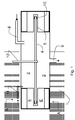
- Figure 1 is an axial cross section through a purifying chamber 1 in a device according to the present invention.
- the purifying chamber 1 is substantially circular cylinder shaped.
- the purifying chamber 1 is divided into to parts, an inlet chamber 2, and an outlet chamber 3, by a separation plate 4.
- the separation plate 4 is a circular plate having a cogged circumference, and is connected to an axle shaft 12 that is substantially axially arranged in the purification chamber 1.
- the separation plate is provided with a plurality of radial arranged cavitations bodies 10.
- the separation plate has a design corresponding to the design of a circular saw, having a plurality of teeth 10 comprising a thickening at the front side relative to the direction of rotation, and where the teeth are tapered towards the rear end of the tooth.
- the cavitations bodies may alternatively be designed as openings in the separation plate, cogs, openings, slits etc.
- the separation plate 4 is arranged in a groove 5 in a ring shaped partition body 6, 6' defining the cylinder wall of the purifying chamber.
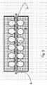
- a plurality of radial arranged channels 7 are preferably arranged in the partition body, the channels being open towards the inlet chamber 2, the outlet chamber 3 and towards the groove 5.
- the channels 4 may have any shape but according to a preferred embodiment, the channels are cylindrical bores being open towards the groove 5 in their entire length.
- the separation body 6, 6' is illustrated as a ring shaped body having a grove within which the separation plate is arranged. Alternatively, the separation body may only comprise an upper separation body 6 that is arranged at the inlet side of the separation plate, and/or additionally comprise a lower separation body 6' at the outlet side of the separation plate.
- the rotation speed of the separation plate is dependent on several factors, such as the diameter of the separation plate.
- a peripheral velocity of about 200 to 300 km/h has been found to be preferred.
- Factors as the amount of and composition of TOC in the water are factors that may influence the optimum speed of rotation.
- the axle shaft 12 is rotated by means of a not shown motor so that the separation plate is rotated.
- the water to be purified is introduced into the inlet chamber 2 through an inlet 8.
- the water flows from the inlet chamber 2 through the channels 7 and the groove 5 along one side of the separation plate.
- the liquid in the channels and in the groove is put into rotation by the rotating separation plate.
- the micro bubbles are brought into the very turbulent water in the channels. In this environment created micro bubbles will collapse and new micro bubbles are created. This results in decomposition of particles purely by physical influence, the creation of free hydroxyl radicals as mentioned above and resulting oxidation of the dispersed organic material in the water.
- the design of the separation plate and the separation body including the channels ensures that the entire volume of water is exposed to the strong shear forces and cavitations, in that the total volume has to pass the cogging of the separation plate.
- a plurality of purifying chambers as described may be serially arranged.
- Two or more purifying chambers connected in series may have their separating plates arranged on axle shaft 12, so that the outlet chamber of the first unit effectively is the inlet chamber of the next, and so on.
- a non-condensable gas such as air
- the added gas promotes the formation of micro bubbles in the liquid and thus promotes the reactions that degrade TOC.
- the gas may be added through a gas inlet 11.
- a prototype of a purifying chamber according to the present invention was built for testing. The first tests were performed for testing of the design of the purifying chamber and see if it satisfied the requirements for velocity of flow, capacity, development of heat, localization of the gas inlet etc.
- the reaction chamber of the prototype had an inner diameter of 306.3 mm (position 2 and 3), having a total height of 300 mm.
- the peripheral velocity of the separation plate 4 could be adjusted from 0 to about 300 km/h.
- the channels 5 in the reaction chamber had a square cross section were the sides were 2.7 mm.
- the velocity of flow during the tests was 600 1/h in test with process water, and 1.2 m 3 /h in tests with crude oil, respectively.
- the tests confirmed that the equipment satisfied the requirements relating to capacity and heat development.
Landscapes
- Engineering & Computer Science (AREA)
- Chemical & Material Sciences (AREA)
- Mechanical Engineering (AREA)
- Chemical Kinetics & Catalysis (AREA)
- Life Sciences & Earth Sciences (AREA)
- Hydrology & Water Resources (AREA)
- Environmental & Geological Engineering (AREA)
- Water Supply & Treatment (AREA)
- Organic Chemistry (AREA)
- Physical Water Treatments (AREA)
- Production Of Liquid Hydrocarbon Mixture For Refining Petroleum (AREA)
- Physical Or Chemical Processes And Apparatus (AREA)
Applications Claiming Priority (1)
| Application Number | Priority Date | Filing Date | Title |
|---|---|---|---|
| NO20055036A NO323794B1 (no) | 2005-10-28 | 2005-10-28 | Anordning for fjerning av opplost organsik materiale |
Publications (1)
| Publication Number | Publication Date |
|---|---|
| EP1780177A2 true EP1780177A2 (fr) | 2007-05-02 |
Family
ID=35432865
Family Applications (1)
| Application Number | Title | Priority Date | Filing Date |
|---|---|---|---|
| EP06123128A Withdrawn EP1780177A2 (fr) | 2005-10-28 | 2006-10-30 | dispositif de décomposition de matière organique |
Country Status (2)
| Country | Link |
|---|---|
| EP (1) | EP1780177A2 (fr) |
| NO (1) | NO323794B1 (fr) |
Cited By (3)
| Publication number | Priority date | Publication date | Assignee | Title |
|---|---|---|---|---|
| CN102350267A (zh) * | 2011-08-31 | 2012-02-15 | 浙江工业大学 | 一种尾涡空化旋转发生器 |
| JP2012512316A (ja) * | 2008-12-16 | 2012-05-31 | エイチ アール ディー コーポレーション | ワックスの高せん断酸化 |
| DE102013013813A1 (de) | 2013-08-22 | 2015-02-26 | SIEVA d.o.o. - poslovna enota Idrija | Verfahren der Behandlung von Wasser durch Kavitation sowie Kavitiervorrichtung |
-
2005
- 2005-10-28 NO NO20055036A patent/NO323794B1/no unknown
-
2006
- 2006-10-30 EP EP06123128A patent/EP1780177A2/fr not_active Withdrawn
Cited By (5)
| Publication number | Priority date | Publication date | Assignee | Title |
|---|---|---|---|---|
| JP2012512316A (ja) * | 2008-12-16 | 2012-05-31 | エイチ アール ディー コーポレーション | ワックスの高せん断酸化 |
| EP2367623A4 (fr) * | 2008-12-16 | 2013-04-24 | H R D Corp | Oxydation d'une cire en présence d'un fort cisaillement |
| CN102350267A (zh) * | 2011-08-31 | 2012-02-15 | 浙江工业大学 | 一种尾涡空化旋转发生器 |
| DE102013013813A1 (de) | 2013-08-22 | 2015-02-26 | SIEVA d.o.o. - poslovna enota Idrija | Verfahren der Behandlung von Wasser durch Kavitation sowie Kavitiervorrichtung |
| US10202288B2 (en) | 2013-08-22 | 2019-02-12 | Sieva D.O.O. | Cavitation device for treatment of water by cavitation |
Also Published As
| Publication number | Publication date |
|---|---|
| NO20055036L (no) | 2007-04-30 |
| NO323794B1 (no) | 2007-07-09 |
| NO20055036D0 (no) | 2005-10-28 |
Similar Documents
| Publication | Publication Date | Title |
|---|---|---|
| US20190185360A1 (en) | Fluid treatment apparatus and processes | |
| EP4132886A1 (fr) | Appareil et procédé d'épuration de l'eau par cavitation | |
| CN111892209B (zh) | 一种便于充分催化氧化的废水处理装置及方法 | |
| RU2585635C1 (ru) | Способ обеззараживания и очистки жидких сред и технологическая линия для его реализации | |
| EP1780177A2 (fr) | dispositif de décomposition de matière organique | |
| KR101682677B1 (ko) | 액상무기물 및 슬러지의 감량 장치 및 방법 | |
| CN119370943B (zh) | 一种双向多级旋转剪切高速多相流水力空化联合文丘里管应用于垃圾渗滤液处理的装置 | |
| CN106830426B (zh) | 一种超重力污水处理装置及工艺 | |
| CN219652858U (zh) | 一种应用于水力空化减泥机的齿形旋转喷嘴 | |
| CN110092447B (zh) | 一种高压放电等离子体高cod乳化废水破乳降解装置 | |
| CN219652859U (zh) | 一种具有齿形旋转喷嘴的水力空化减泥机 | |
| NL2021149B1 (en) | Method and system for the purification of contaminated water | |
| CN115504529B (zh) | 一种高效空化破壁发生装置 | |
| CN106799122B (zh) | 一种超重力脱铵盐装置及工艺 | |
| CN118439705B (zh) | 复合式絮凝剂解离装置 | |
| US20060283788A1 (en) | Tri-clone system | |
| CN120486508B (zh) | 一种用于河道污泥的处理设备及处理方法 | |
| RU2524601C1 (ru) | Установка безреагентной очистки и обеззараживания воды | |
| Madhu et al. | Escalation of degradation of malachite green and Methyl violet using hydrodynamic cavitations using different orifice geometry | |
| JPH0515753A (ja) | 気液接触装置 | |
| RU2503483C2 (ru) | Устройство и система для очистки отработанной воды | |
| CN211688614U (zh) | 一种化工生产废水处理装置 | |
| CN224015382U (zh) | 一种针对废水中油水处理的装置 | |
| Bethi et al. | A historical approach for integration of cavitation technology with conventional wastewater treatment processes | |
| CN102961904A (zh) | 轻质滤料过滤器 |
Legal Events
| Date | Code | Title | Description |
|---|---|---|---|
| PUAI | Public reference made under article 153(3) epc to a published international application that has entered the european phase |
Free format text: ORIGINAL CODE: 0009012 |
|
| AK | Designated contracting states |
Kind code of ref document: A2 Designated state(s): AT BE BG CH CY CZ DE DK EE ES FI FR GB GR HU IE IS IT LI LT LU LV MC NL PL PT RO SE SI SK TR |
|
| AX | Request for extension of the european patent |
Extension state: AL BA HR MK YU |
|
| STAA | Information on the status of an ep patent application or granted ep patent |
Free format text: STATUS: THE APPLICATION IS DEEMED TO BE WITHDRAWN |
|
| 18D | Application deemed to be withdrawn |
Effective date: 20090505 |