EP1780178A2 - procédé de traitement des eaux usées et installation de décomposition - Google Patents
procédé de traitement des eaux usées et installation de décomposition Download PDFInfo
- Publication number
- EP1780178A2 EP1780178A2 EP06022384A EP06022384A EP1780178A2 EP 1780178 A2 EP1780178 A2 EP 1780178A2 EP 06022384 A EP06022384 A EP 06022384A EP 06022384 A EP06022384 A EP 06022384A EP 1780178 A2 EP1780178 A2 EP 1780178A2
- Authority
- EP
- European Patent Office
- Prior art keywords
- clarifier
- clarification
- waste
- wastewater
- inlet
- Prior art date
- Legal status (The legal status is an assumption and is not a legal conclusion. Google has not performed a legal analysis and makes no representation as to the accuracy of the status listed.)
- Withdrawn
Links
Images

Classifications
-
- C—CHEMISTRY; METALLURGY
- C02—TREATMENT OF WATER, WASTE WATER, SEWAGE, OR SLUDGE
- C02F—TREATMENT OF WATER, WASTE WATER, SEWAGE, OR SLUDGE
- C02F3/00—Biological treatment of water, waste water, or sewage
- C02F3/02—Aerobic processes
- C02F3/12—Activated sludge processes
- C02F3/1236—Particular type of activated sludge installations
- C02F3/1242—Small compact installations for use in homes, apartment blocks, hotels or the like
-
- Y—GENERAL TAGGING OF NEW TECHNOLOGICAL DEVELOPMENTS; GENERAL TAGGING OF CROSS-SECTIONAL TECHNOLOGIES SPANNING OVER SEVERAL SECTIONS OF THE IPC; TECHNICAL SUBJECTS COVERED BY FORMER USPC CROSS-REFERENCE ART COLLECTIONS [XRACs] AND DIGESTS
- Y02—TECHNOLOGIES OR APPLICATIONS FOR MITIGATION OR ADAPTATION AGAINST CLIMATE CHANGE
- Y02W—CLIMATE CHANGE MITIGATION TECHNOLOGIES RELATED TO WASTEWATER TREATMENT OR WASTE MANAGEMENT
- Y02W10/00—Technologies for wastewater treatment
- Y02W10/10—Biological treatment of water, waste water, or sewage
Definitions
- the invention relates to a treatment process for substantially aerobic wastewater treatment of a biological waste, especially kitchen and household waste, polluted wastewater and, in particular for carrying out the process, to a decomposition plant with a clarifier, which has an inlet and a drain and with a Air delivery device that introduces air to the bottom of the clarifier.
- the DE 199 05 633 C1 describes a treatment process for substantially aerobic wastewater treatment in a container and for carrying out the method a decomposition plant.
- the Method comprises the steps of batchwise feeding of waste water at the upper end of a nitrification zone, dropping of the supplied wastewater charge in the nitrification zone, intermittent venting at the lower end of the nitrification zone in countercurrent to the sinking wastewater charge by the aeration caused, transient overflow of partially purified wastewater at the upper end of the Nitrification zone into a non-ventilated descending zone or circulation zone.
- the DE 195 23 842 C2 describes a garbage disposal device, in particular for the disposal of biodegradable kitchen and / or household waste with a crushing device and a connection to a sewer system and with a filling container with a filling opening not serving as Abwasserabpound for filling the waste to be disposed, wherein the crushing device a within the filling container comprises rotating designed as a pump rotor for pumping the shredded waste knife.
- a waste removal line for introducing the shredded waste into a branch of a sewer pipe of a sink and / or wash basin is provided.
- From the DE 202 05 956 U1 is a feed station for a biowaste disposal device known. It is preferably installed in a kitchen sink and has a downstream crushing mill for the biowaste.
- a compact wastewater treatment plant known, which is particularly suitable for the purification of municipal domestic wastewater and which has a primary sedimentation tank, an aeration tank provided with aerator and a secondary sedimentation tank, wherein a basin is connected to the other via passage openings for the liquid.
- At least one mixer is arranged in the primary clarifier and optionally in the activated sludge tank and a pumping line connects the secondary clarifier with the primary clarifier, the small wastewater treatment plant preferably being designed in a cylindrical design.
- the present invention has for its object to improve a treatment process or a decomposition plant of the type mentioned.
- this object is achieved by the following steps: feeding the polluted waste water into the clarifier below the water level of the clarifier, aerating the clarifier from the bottom of the clarifier and discharging the purified waste water.
- the object is characterized solved that the inlet for dirty wastewater is designed such that the wastewater is introduced below the water level of the clarifier in the clarifier.
- the inventive proposal which is used both in the method and in the decomposition plant according to the invention, it follows that an effective and reliable Odor Abschottung is achieved.
- This makes it possible that the inventive method or the decomposition plant according to the invention also in the interior, for example in the kitchen u.s.w. can be used.
- a costly insulation to avoid freezing of the decomposition plant in winter not necessary, which surprisingly significantly increases the acceptance of the invention, as an effective wastewater treatment without much on-site effort (for example, insulation of an external sewer with a corresponding treatment plant) manages.
- a decomposition process of the waste is almost more effective at room temperature than a decomposition process with sometimes high temperature fluctuations.
- the polluted wastewater is fed via an inlet with a connection in the bottom region of the clarifier.
- the odor trap is efficient, that is, that it works effectively even with low-filled clarifier and wastewater can always go through from the bottom of the biological decomposition process and thus optionally in a multi-chamber system a maximum long decomposition can be provided ,
- a filter device arranged over a large area is therefore advantageous, since it less or hardly clogs a drain and thus ensures a long-lasting operation of the treatment process or the decomposition plant.
- the filter device is thus preferably arranged on the water surface at least in the chamber with the drain.
- a filter is considered, which fills far more than 25%, in a preferred variant, more than 50% of the cross-sectional area of the container.
- the filter device which is located at the level of the water level in the clarifier, it is ensured that only purified wastewater comes to drain and larger by the sewage treatment plant (not yet) decomposed solids in the Clarifier, as long as they are either completely degraded or decomposed or until a revision ie emptying of the clarifier takes place.
- the filter device is made of a coarsely porous plastic material, preferably a PVC sponge.
- the waste before feeding into the clarifier in particular to a grain size of 3-10 mm, preferred 4-5 mm, crushed by means of a crushing device.
- a crushing device which may be a grinder or a mill, is known in the art and for example in the DE 195 23 842 C2 or DE 202 05 956 U1 described.
- the crusher may comprise either a rotary knife or shredder or grinder or any other suitable mechanism to provide a desired grain size (about 4 to 5 mm) of the biodegradable material.
- the crushing device can also be switched on by means of a manually operated switch.
- the entire clarifier is ventilated, optionally in the case of several chambers these chambers of the clarifier are also ventilated.
- the ventilation is already carried out from ground level or at ground level.
- the entire clarifier is mixed with small air bubbles.
- the aeration of the sewage tank is continuously or permanently with an air introduction device.
- the air introduction device is therefore arranged in the entire clarifier or in all clarification chambers.
- the air introduction device below the bottom of the clarifier container supply lines to introduce air at ground level in the clarifier, wherein out of the bottom of the clarifier container arranged air injection holes pumped air flows out.
- the air introduction device has a small, known from the prior art pump, which is dimensioned depending on the volume of the clarifier in the power and size and has the lowest possible energy consumption.
- the power range of the electrically operated pump, which can work continuously, is between 20-100 W, preferably in the range of 30-50 W, more preferably in the range between 35-45 W. Since the clarifier is permanently ventilated, a continuous nitrification is safe posed.
- the comminuting device preferably has a control circuit for switching on and off a drive motor of the comminuting device.
- the crushing device is only turned on due to the control circuit when biological waste is supplied.
- a sensor or a switch could be provided as an actuator.
- the actuator could be coupled to the faucet, so that when the faucet is open, the shredding device is switched on at the same time and possibly switched off again with a corresponding delay, and optical or electronic sensors, which are common in automatic rinsing tanks, can also be used as actuators.
- a comminuting device is arranged in the waste water outlet of the sink before the inlet of the clarification container.
- the comminution device is designed, for example, as a comminution mill.
- a waste opening is arranged in front of the comminution device, by means of which the comminution device can be charged directly with biowaste.
- the waste opening is of such a size that conventional biowaste can be easily absorbed.
- the crushing device can alternatively both via the waste opening as also be charged via the wastewater drainage of the sink (possibly mixed with water or other liquids) with biowaste.
- the clarifier consists of an opaque material.
- the clarifier has in a preferred embodiment, two partitions, which divides the clarifier into three to be traversed by the wastewater chambers.
- a partition extends from the bottom of the clarifier and must be overflowed by the sewage.
- the second partition extends from the ceiling area to the bottom of the clarifier, with the partition being open at the bottom so that the sewage has to pass through this bottom of the clarifier to get to the drain.
- the wastewater in the clarifier is transferred when crossing the first partition from a primary clarifier in a Hauptteilsch.
- a venting channel is provided for the expiration.
- the filter device is in this embodiment in the last, to be traversed by the wastewater third clarification chamber at the level of the water level.
- the biological waste is decomposed in the sewage tank as a result of microorganisms contained in the waste and sewage and forming, until the decomposed waste can pass through the coarse-pored filter.
- enzymes in the clarifier can be added via an opening in the ceiling region of the clarifier. This addition can of course also via a metering device a controller to be automated.
- the clarifier may have at least one inspection opening with an associated lid and a seal to clean the clarifier of solids at regular intervals or depending on the degree of contamination or replace the filter device.
- the clarifier has, depending on the size of the household, i. the person living in the household, a volume of about 15-50 1, preferably between 20-25 1 on.
- a rinsing pump can be arranged in a flushing channel, which leads to the expiration of the decomposition plant.
- the flushing channel can be opened by a latch to flush the clarifier at regular intervals in a cleaning process.
- the intervals of the flushing can also be controlled by electronic circuits by means of sensors.
- the decomposition plant has a waste opening in front of the comminution device in such a size, so that also conventional biowaste can be taken up. This significantly reduces the amount of biowaste in a garbage bin, thus avoiding the problems associated with a biowaste bin and subsequent landfill disposal.
- the inlet is designed with a first connection above the water level and a second connection in the bottom area of the clarification tank in order to introduce wastewater into the clarification tank.
- an upper part of the inlet and the outlet are arranged at the same height.
- the feed is led to the bottom of the clarifier.
- the clarifier is located lower. This is a siphon through the Water column created in the inlet to seal the odors of the clarifier.
- a smaller siphon device is interposed in front of or in the inlet.
- the decomposition plant can be arranged in the drainage path of the wastewater, in particular of kitchen sinks, somewhere in the building, so that the wastewater is then discharged into the sewage system.
- the decomposition plant is dimensioned such that it can find space under a sink substantially and in particular behind or instead of a siphon of a kitchen sink is arranged and also preferably the drain of the sink serves as a waste opening.
- the decomposition system has an odor-tight housing and the housing has a separate vent line or venting takes place via the channel of the outlet.
- venting takes place optionally either via the drain as in the rest of the wastewater area, or by a separate vent line that can leave the building at a suitable location.
- a pump may be disposed in the inlet to feed the waste water to the clarifier promote.
- Fig. 1 shows schematically a decomposition plant 1 with a clarifier 2.
- the clarifier 2 has an inlet 3 and a drain 4.
- the inlet 3 has a first connection 27 above the water level 32 of the clarification tank 2 and leads via a second connection 23 to the bottom 25 of the clarification tank 2.
- a well-known from the households in sink siphon is created to produce an odor finish.
- the conventional siphon is replaced by the decomposition plant 1 with siphon function.
- the sewage tank 2 has, at the level of the water level 32, a two-dimensional filter device 6, preferably of a coarse-pored, sheet-like material.
- the material may be PVC and is preferably a sponge material known from the kitchen environment.
- the large-area filter material has the advantage that the drain 4 is not blocked and only purified wastewater 40 can pass through.
- the filter device 6 clogs itself not so fast and comes from without additional, elaborate cleaning facilities. Stable long operation is guaranteed.
- the air introduction device 5 comprises a pump, for example an aquarium pump, which operates permanently and consumes as little energy as possible.
- Air supply lines of the air introduction device 5 are arranged under the bottom 25 of the clarifier 2, wherein air introduction openings 52 are distributed throughout the bottom 25 of the clarifier 2, so that the entire clarifier 2 is mixed with air and the clarifier is used efficiently, so that no shadows or not With air flowed spaces in the clarifier can arise.
- a comminution device 7 designed as a mill is arranged at the inlet 3 and comminutes the biological kitchen and household waste coming from a waste opening 8 to a particle size of 4-5 mm.
- the crushing device 7 is essentially known from the prior art. She is for example in the DE 202 05 956 U1 described and is offered, inter alia, under the name "Sinkmaster" by the company SBM Maschinen GmbH.
- the waste opening 8 replaces the drainage opening of a conventional sink 9.
- the waste opening 8 is preferably designed to be larger than a conventional sink drainage opening in order to accommodate larger biological waste.
- a simple waste disposal apparatus is provided for disposing of biodegradable kitchen and household waste that disposes of the waste substantially directly at the place where the waste is generated.
- the biodegradable material is already moistened with a minimum use of components in the sink, crushed in the mill and rinsed with the wastewater 30 in the clarifier 2.
- the purification process works as follows: In the sink, the biodegradable food scraps and food particles are introduced into the waste opening 8. Subsequently, they are crushed in the crushing device 7. By means of the rinsing water, these crushed parts are fed into the clarifier 2 via the inlet 3. In the clarifier 2, the biological solid parts of microorganisms are decomposed by means of an air. The nitrification always takes place without the addition of enzymes. However, enzymes can improve and accelerate the clarification process. There are always microorganisms in the old waste water 20 in the or the clarification chambers of the clarifier 2, which can decompose fresh waste.
- Fig. 2 shows another particular embodiment of the decomposition plant 1 with a clarifier 2, which has three chambers 2a, 2b, 2c due to partitions 10.
- the individual chambers 2a, 2b, 2c must be traversed by the wastewater 20 due to the arrangement of the partitions 10 - that is, due to a forced operation.
- the partition wall 10 of the first chamber 2a extends from the bottom 25 over the water level of the clarifier 2, which is defined by the height of the drain 4, with a distance d.
- the waste water 20 must overflow the threshold with the distance d from the first partition wall 10 in order to reach the second chamber 2b of the clarification tank 2.
- the second partition wall extends from the ceiling region of the clarification container 2 in the direction of the bottom region of the clarification container 2 with an open distance D to the bottom, so that the wastewater 20 has to pass through this bottom region in order to reach the third chamber 2c.
- the filter device 6 Floating at the height of the water level 32 of the third chamber 2c is the filter device 6, which lets only purified wastewater 40 through.
- the air introduction device 5 supplies air from the bottom 25 to all three chambers 2a, 2b, 2c. Due to the aerobic decomposition process in all three chambers, the wastewater is 20 cleaned more efficiently and faster, rot and thus odor generation are avoided.
- the air generated by the air introduction device 5 flows directly out of the bottom 25 of the clarifier 2 out of air introduction holes 15.
- a vent channel 11 is provided to the outlet 4 of the clarifier 2.
- the clarifier 2 has an inspection opening 12, which is sealed with a seal 13 in order to replace the filter 6 can.
- a flushing pump 14 is provided with a flushing channel 15 which leads from the bottom region of the clarifier 2 to the outlet 4.
- the flushing channel 15 is opened and closed by a barrier 16 which is arranged in front of the pump 14.
- the clarifier 2 can be cleaned if necessary.
- a (not shown) control can be provided which opens the barrier 16 for cleaning the clarifier 2 when a measurable limit is exceeded due to increasing accumulation of solids and the flushing pump 14 turns on. The limit of solid accumulation can be determined by known sensors.
- the controller then turns off after a designated time or procedure, the purge pump 14 and closes the flushing channel with the barrier 16. In such an automatic control of a switchable pure water inlet is provided.
- the crushing device 7 can also be turned on and off due to a control circuit 17. From the prior art, a number of possibilities for such a control circuit 17 are known. The switching on and off of the crushing device can be synchronized by means of a control circuit 17 with the faucet of a sink, wherein the switch-off is conveniently delayed. An optical sensor, as known from automatic sink devices, can also serve as an actuator for the control of the crushing device.
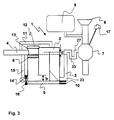
- Fig. 3 shows a decomposition plant 1, according to FIG. 2 with the difference that the waste opening 8 is not under a sink 9 is arranged, but is located separately next to a sink.
- drainage water can also be supplied from the sink 9 to the comminution device 7.
- the sink and the waste opening 8 are designed separately separately.
- the control circuit 17 is manually operated to turn on the comminution device 7 and turn it off in advance.
- the control circuit 17 may comprise either an on / off switch or a button.
- a further smaller siphon device 33 which ensures that no smaller resulting decay odors can get into the waste opening 8.
Landscapes
- Life Sciences & Earth Sciences (AREA)
- Biodiversity & Conservation Biology (AREA)
- Microbiology (AREA)
- Hydrology & Water Resources (AREA)
- Engineering & Computer Science (AREA)
- Environmental & Geological Engineering (AREA)
- Water Supply & Treatment (AREA)
- Chemical & Material Sciences (AREA)
- Organic Chemistry (AREA)
- Processing Of Solid Wastes (AREA)
- Crushing And Pulverization Processes (AREA)
- Biological Treatment Of Waste Water (AREA)
Applications Claiming Priority (1)
| Application Number | Priority Date | Filing Date | Title |
|---|---|---|---|
| DE200510051754 DE102005051754A1 (de) | 2005-10-27 | 2005-10-27 | Klärverfahren und Zersetzungsanlage |
Publications (2)
| Publication Number | Publication Date |
|---|---|
| EP1780178A2 true EP1780178A2 (fr) | 2007-05-02 |
| EP1780178A3 EP1780178A3 (fr) | 2008-06-25 |
Family
ID=37621961
Family Applications (1)
| Application Number | Title | Priority Date | Filing Date |
|---|---|---|---|
| EP20060022384 Withdrawn EP1780178A3 (fr) | 2005-10-27 | 2006-10-26 | procédé de traitement des eaux usées et installation de décomposition |
Country Status (3)
| Country | Link |
|---|---|
| US (1) | US20070102355A1 (fr) |
| EP (1) | EP1780178A3 (fr) |
| DE (1) | DE102005051754A1 (fr) |
Cited By (1)
| Publication number | Priority date | Publication date | Assignee | Title |
|---|---|---|---|---|
| FR2999562A1 (fr) * | 2012-12-17 | 2014-06-20 | P R D | Station individuelle d'epuration des eaux, incluant une cloison siphoide delimitant une zone siphoide dans laquelle est dispose un materiau filtrant |
Families Citing this family (3)
| Publication number | Priority date | Publication date | Assignee | Title |
|---|---|---|---|---|
| US8801930B2 (en) * | 2009-03-26 | 2014-08-12 | Zeguo Qiu | Method and apparatus of solid wastes automatic collection ductwork evacuation and comprehensive utilization |
| FR3013346A1 (fr) * | 2013-11-15 | 2015-05-22 | P R D | Station d'epuration des eaux, incluant des moyens d'agitation des boues flottantes au moyen de bulles |
| DE202014010155U1 (de) * | 2014-12-22 | 2016-03-24 | Hugo Vogelsang Maschinenbau Gmbh | Feststoff-Ausbringmodul |
Family Cites Families (25)
| Publication number | Priority date | Publication date | Assignee | Title |
|---|---|---|---|---|
| US2798228A (en) * | 1954-03-29 | 1957-07-09 | Carl F Boester | Waste disposal system |
| DE1507471A1 (de) * | 1965-12-24 | 1969-04-03 | Bbc Brown Boveri & Cie | Als Haushaltsgeraet ausgebildetes Geraet zur Behandlung im Haushalt anfallender Abfaelle |
| NL7112853A (en) * | 1970-10-02 | 1972-04-05 | Small sewage treatment unit - with all parts housed in one main tank | |
| US3807565A (en) * | 1972-07-03 | 1974-04-30 | Aerobiotic Sciences Inc | Sewage disposal system |
| AT355518B (de) * | 1974-12-04 | 1980-03-10 | Renner Helmut Dipl Ing Dr Tech | Abwasserklaeranlage |
| DE2504164A1 (de) * | 1975-02-01 | 1976-08-05 | Bosch Siemens Hausgeraete | Vorrichtung zum beseitigen von stoffen, insbesondere von haushalts- und kuechenabfaellen |
| FR2310969A1 (fr) * | 1975-05-15 | 1976-12-10 | Chataignier Jean | Installation de traitement des eaux ne comportant pas de piece mecanique mobile en contact avec le liquide a traiter |
| US3984322A (en) * | 1975-05-20 | 1976-10-05 | Howard Peasley And Associates | Sewage treatment apparatus |
| DE2641395A1 (de) * | 1976-04-20 | 1977-11-03 | Toshio Yagi | Abfallbeseitigungsvorrichtung |
| US4139471A (en) * | 1976-09-07 | 1979-02-13 | Dominick Foti | Sewage treatment unit |
| DE2752190A1 (de) * | 1977-11-23 | 1979-05-31 | Roth Kg Metallwerk | Kleinklaervorrichtung |
| US4271540A (en) * | 1979-04-26 | 1981-06-09 | Clifton Ronald M | Sewage system with comminutor |
| US4325823A (en) * | 1980-05-12 | 1982-04-20 | Tom Graham & Associates | Wastewater treatment system |
| DE3527772A1 (de) * | 1985-08-02 | 1987-02-12 | Friedrich Maschke | Vorrichtung zum zerkleinern von abfaellen |
| US5114586A (en) * | 1990-08-01 | 1992-05-19 | Frank Humphrey | Sanitation system |
| JPH06102196B2 (ja) * | 1991-01-30 | 1994-12-14 | 岩雄 植田 | 雑排水の処理装置 |
| US5190646A (en) * | 1991-03-11 | 1993-03-02 | Nikki Hanbai Co., Ltd. | Wastewater treating biological film tank |
| US5783071A (en) * | 1994-01-11 | 1998-07-21 | Delta Environmental Products, Inc. | Apparatus for treating wastewater |
| DE29504584U1 (de) * | 1994-12-06 | 1995-05-11 | Environtec Gesellschaft zur Erfassung und Bewertung von Altlasten, Abfall und Abwasser mbH, 10997 Berlin | Kleinkläranlage mit einer Mehrkammergrube |
| DE19523842C2 (de) * | 1995-06-30 | 2001-12-13 | Hubert Weishaupt | Abfallbeseitigungsvorrichtung, insbesondere zur Beseitigung von biologisch abbaubaren Küchen- und Haushaltsabfällen |
| US5609754A (en) * | 1995-09-07 | 1997-03-11 | Stuth; William L. | Secondary sewage treatment system |
| WO1998034880A1 (fr) * | 1996-02-08 | 1998-08-13 | Advent Corporation | Systeme integre de traitement d'eaux residuaires a vitesse induite des boues |
| US5766459A (en) * | 1996-02-08 | 1998-06-16 | Carl E. Adams, Jr. | Integrated wastewater treatment system with induced sludge velocity |
| AT403374B (de) * | 1996-05-02 | 1998-01-26 | Herbert Weiss | Kompakte kleinkläranlage |
| DE10158634A1 (de) * | 2001-11-29 | 2003-06-12 | Kordes Gmbh Forschung Und Entw | Kleinkläranlage |
-
2005
- 2005-10-27 DE DE200510051754 patent/DE102005051754A1/de not_active Withdrawn
-
2006
- 2006-10-26 EP EP20060022384 patent/EP1780178A3/fr not_active Withdrawn
- 2006-10-27 US US11/588,379 patent/US20070102355A1/en not_active Abandoned
Cited By (1)
| Publication number | Priority date | Publication date | Assignee | Title |
|---|---|---|---|---|
| FR2999562A1 (fr) * | 2012-12-17 | 2014-06-20 | P R D | Station individuelle d'epuration des eaux, incluant une cloison siphoide delimitant une zone siphoide dans laquelle est dispose un materiau filtrant |
Also Published As
| Publication number | Publication date |
|---|---|
| EP1780178A3 (fr) | 2008-06-25 |
| DE102005051754A1 (de) | 2007-05-03 |
| US20070102355A1 (en) | 2007-05-10 |
Similar Documents
| Publication | Publication Date | Title |
|---|---|---|
| DE4394475B4 (de) | Verfahren zur Beseitigung und Behandlung von Abfall | |
| DE2933102A1 (de) | Vorrichtung fuer schienenfahrzeuge o.dgl. zur lagerung und beseitigung menschlicher ausscheidungsstoffe | |
| DE20107576U1 (de) | Vorrichtung zur Trocknung von Feuchtgut und Klarwasserabzugrohr für eine Kläranlage | |
| KR20140060609A (ko) | 3차 감량기 일체형 음식물쓰레기 처리장치 | |
| EP0732457A2 (fr) | Procédé et dispositif de récupération d'eau usagée | |
| KR101669813B1 (ko) | 압착 장치를 이용한 초기우수처리시스템 | |
| EP1927521B1 (fr) | Dispositif et procédé de réduction des nuisances olfactives dans les installations de lavage de véhicules | |
| EP1780178A2 (fr) | procédé de traitement des eaux usées et installation de décomposition | |
| EP0688304B1 (fr) | Procede d'epuration biologique d'eaux usees, a systeme de tamponnage integre | |
| DE19523842C2 (de) | Abfallbeseitigungsvorrichtung, insbesondere zur Beseitigung von biologisch abbaubaren Küchen- und Haushaltsabfällen | |
| WO1996033136A1 (fr) | Station d'epuration | |
| WO2002042569A1 (fr) | Dispositif de toilettes | |
| AU2006233198A1 (en) | Bacteria inoculation system with earthworm humus, used as a treatment of contaminated water (inoculom) | |
| DE19717854C1 (de) | Verfahren und Kläranlage zum biologischen Reinigen von organisch belastetem Abwasser | |
| DE3390397T1 (de) | Verfahren und Vorrichtung zur Abwasserreinigung | |
| EP1108455B1 (fr) | Dispositif pour la séparation d'eau de pluie pour l'obtention d'eau de récupération prénettoyée | |
| DE19921405A1 (de) | Verfahren und Vorrichtung zur Entsorgung von verrottbaren Abfällen | |
| EP1723084A2 (fr) | Installation et procede de traitement de matieres fecales et unite membrane | |
| DE19737691B4 (de) | Anlage zur Reinigung von Abwässern ohne Entstehung von Klärschlamm | |
| EP1760046B1 (fr) | Purificateur d'eau compact pour étangs | |
| DE4330422C1 (de) | Verfahren und Anlage zur Entsorgung der Inhalte von Mehrkammer- und Sammelgruben | |
| CH681063A5 (en) | Cleaner for sewage from multi-chamber cesspit - comprises container including dwell zone and filter and out-flow zones to give clean water without using chemicals | |
| DE202025101378U1 (de) | Einrichtung zur Speicherung von Grauwasser und System zur Grauwasserverwendung | |
| DE29707646U1 (de) | Kläranlage zum biologischen Reinigen von organisch belastetem Abwasser | |
| DE29513467U1 (de) | Vorrichtung zur Entsorgung von organischen Abfällen in Gebäuden |
Legal Events
| Date | Code | Title | Description |
|---|---|---|---|
| PUAI | Public reference made under article 153(3) epc to a published international application that has entered the european phase |
Free format text: ORIGINAL CODE: 0009012 |
|
| AK | Designated contracting states |
Kind code of ref document: A2 Designated state(s): AT BE BG CH CY CZ DE DK EE ES FI FR GB GR HU IE IS IT LI LT LU LV MC NL PL PT RO SE SI SK TR |
|
| AX | Request for extension of the european patent |
Extension state: AL BA HR MK YU |
|
| PUAL | Search report despatched |
Free format text: ORIGINAL CODE: 0009013 |
|
| AK | Designated contracting states |
Kind code of ref document: A3 Designated state(s): AT BE BG CH CY CZ DE DK EE ES FI FR GB GR HU IE IS IT LI LT LU LV MC NL PL PT RO SE SI SK TR |
|
| AX | Request for extension of the european patent |
Extension state: AL BA HR MK RS |
|
| AKX | Designation fees paid | ||
| STAA | Information on the status of an ep patent application or granted ep patent |
Free format text: STATUS: THE APPLICATION IS DEEMED TO BE WITHDRAWN |
|
| 18D | Application deemed to be withdrawn |
Effective date: 20081230 |
|
| REG | Reference to a national code |
Ref country code: DE Ref legal event code: 8566 |