EP1780340B1 - Dispositif de balayage et procédé d'opération associé - Google Patents
Dispositif de balayage et procédé d'opération associé Download PDFInfo
- Publication number
- EP1780340B1 EP1780340B1 EP06016717.8A EP06016717A EP1780340B1 EP 1780340 B1 EP1780340 B1 EP 1780340B1 EP 06016717 A EP06016717 A EP 06016717A EP 1780340 B1 EP1780340 B1 EP 1780340B1
- Authority
- EP
- European Patent Office
- Prior art keywords
- road sweeper
- accordance
- road
- fan
- sweeper
- Prior art date
- Legal status (The legal status is an assumption and is not a legal conclusion. Google has not performed a legal analysis and makes no representation as to the accuracy of the status listed.)
- Active
Links
Images




Classifications
-
- E—FIXED CONSTRUCTIONS
- E01—CONSTRUCTION OF ROADS, RAILWAYS, OR BRIDGES
- E01H—STREET CLEANING; CLEANING OF PERMANENT WAYS; CLEANING BEACHES; DISPERSING OR PREVENTING FOG IN GENERAL CLEANING STREET OR RAILWAY FURNITURE OR TUNNEL WALLS
- E01H1/00—Removing undesirable matter from roads or like surfaces, with or without moistening of the surface
- E01H1/08—Pneumatically dislodging or taking-up undesirable matter or small objects; Drying by heat only or by streams of gas; Cleaning by projecting abrasive particles
- E01H1/0863—Apparatus loosening or removing the dirt by blowing and subsequently dislodging it at least partially by suction ; Combined suction and blowing nozzles
-
- E—FIXED CONSTRUCTIONS
- E01—CONSTRUCTION OF ROADS, RAILWAYS, OR BRIDGES
- E01H—STREET CLEANING; CLEANING OF PERMANENT WAYS; CLEANING BEACHES; DISPERSING OR PREVENTING FOG IN GENERAL CLEANING STREET OR RAILWAY FURNITURE OR TUNNEL WALLS
- E01H1/00—Removing undesirable matter from roads or like surfaces, with or without moistening of the surface
- E01H1/08—Pneumatically dislodging or taking-up undesirable matter or small objects; Drying by heat only or by streams of gas; Cleaning by projecting abrasive particles
- E01H1/0827—Dislodging by suction; Mechanical dislodging-cleaning apparatus with independent or dependent exhaust, e.g. dislodging-sweeping machines with independent suction nozzles ; Mechanical loosening devices working under vacuum
Definitions
- the invention relates to a sweeper having a fan, with a suction-side line system connected to the fan in the flow direction of the transport air upstream of the fan and with a pressure-side line system connected downstream of the fan with the fan in the direction of flow of the transport air.
- the fan is used to suck in by means of an inlet of a nozzle assembly with rubbish laden transport air and to guide the loaded transport air through a Kehrricht notioner in which settle the coarser components of the rubbish.
- the transport air is optionally passed with the fine components through a filter and then fed to the blower.
- the transport air is blown out after passing through the blower through a nozzle assembly from the sweeping vehicle. It is provided that the transport air is completely blown out again after a part of the dirt components was deposited in the Kehrricht momenter or filter.
- the present invention is therefore the object of developing a sweeper of the type mentioned in such a way that their cleaning performance is improved.
- a sweeper with the features of claim 1.
- the pressure-side line system can be connected to the suction-side line system or is connected, so that at least part of the transport air located in the pressure-side line system can be fed to the suction-side line system.
- the blower exhaust air is at least partially performed in the recirculation mode, whereby the cleaning performance improved considerably.
- the fan is preferably in suction connection with an inlet in flow connection, can be sucked through the transport air during operation of the blower from the environment.
- This inlet may be part of a nozzle assembly and is oriented relative to the sweeping devices, such as a sweeping roller or a disc brush, so as to receive the sweeping motion moved by the sweeping devices.
- the fan is on the pressure side with an outlet in flow communication, can be delivered by the transport air during operation of the blower to the environment, wherein the outlet disposed in the region of said inlet and may also be part of a nozzle assembly.
- a line section connecting the suction side and the pressure side line system in which an adjustable flap is arranged such that the amount of transport air flowing from the pressure side into the suction side line system can be varied.
- the flap can be designed in such a way that the line section connecting the line systems can be completely shut off. In this case, the recirculation system would be switched off, that is, 100% of the intake air is discharged again.
- the flap is designed such that up to 100%, preferably up to 70% or up to 30% of the blower exhaust air can be fed to the suction-side line system. If 100% of the blower exhaust air supplied to the suction-side piping system, this means that a complete recirculation mode is present, that is, that no exhaust air is discharged. Preferably, this proportion is up to 70% or, for example, up to 30%, so that a part of the fan air supplied to the blower air blower and a part of supplied from the environment air. These values are just examples. Of course, other values or range limits are selectable.
- the sweeper has a Kehrricht mimetic and that the pressure-side piping system is connected to the suction-side pipe system upstream of the Kehrricht justifyers or is in communication.
- the sweeper has one or more filters, and that the pressure-side piping system with the suction-side piping system upstream of the filter or in the case of multiple filters between two filters is connectable.
- the filter or filters are preferably located downstream of the refuse container.
- the sweeper may have a sweeping roller. This is preferably arranged such that it can be pivoted into a position inclined relative to the horizontal. This results in the advantage that road bumps can be compensated because the roller always adapts to the road surface.
- the sweeping roller can be arranged to oscillate on a stationary or pivotable component of the sweeper.
- the sweeping roller can be arranged to oscillate on a pivotally arranged tie rod, in particular on the tie rod ends thereof.
- the sweeper has a sweeping roller which is arranged such that it is pivotable relative to the longitudinal axis of the sweeper to the right or left.
- the sweeper can be designed as a one-way sweeping and sucking machine or as a two-way sweeping and sucking machine. Therefore, it is advantageous if the sweeping roller can be selectively pivoted from the right to the left side or vice versa.
- the sweeping roller can communicate with a tie rod. This can be pivotable about a vertical or substantially vertical axis, so that the sweeping roller is accordingly pivotable to the right or left.
- the sweeper has one or more units, which are jointly supported on a arranged on the sweeper holding part, which consists of a substantially vertically arranged bearing pin on which one or more sleeves are rotatably mounted on each one or more units are attached.
- the aggregates may be, for example, a plate broom and / or act around the inlet for receiving transport air and / or the outlet for the discharge of transport air.
- the sweeping unit is a disc brush, which is arranged pivotable about two substantially horizontally and transversely to each other extending axes.
- the one axis substantially transverse and the other axis extending substantially longitudinally to the direction of travel of the sweeper, as shown in DE 40 01 088 A1 evident.
- the disc brush is pivoted about the axis extending transversely to the direction of travel downwards, so that it sweeps over a kidney-shaped area of the road surface. It is also possible, for example, to incline the disc brush to the pointing in the direction of travel axis on the gutter.
- the disc brush is resiliently biased in an inclined position in which it is pivoted about the first axis in the direction of travel to the road surface and about the second axis to a gutter or in the direction of the curve, the inclination angle by stops are limited.
- the disc broom can be supported for example on prestressed Kunststofftorsionsbuchsen.
- a device is provided for pivoting the pan plate about the second axis against a bias.
- the disc brush may be substantially vertically adjustable while spring biased so that when vertical adjustment as a result of uneven ground on the road surface, the inclination angles are maintained when the disc brush touches the road surface.
- the disc brush has a suspension having as a resilient element only a single rubber spring (Silent bush), in the inner bush, the support shaft of the disc plate is held, so that the disc brush is resiliently pivotable about two intersecting axes, of which one approximately in the vehicle longitudinal direction and the other extends transversely to the vehicle.
- Silent bush a single rubber spring
- the sweeper has at least one disc brush with a suspension for the disc brush, which has a pivotable about a vertical axis to the vehicle frame, substantially horizontal pivot arm on which an outer tube piece is fixed with a vertical axis in which non-rotatably guided an inner pipe section axially displaceable and retractable by a pneumatic cylinder, and having a support frame supported on the vehicle frame or preferably attached to the lower end of the inner pipe piece support plate, on which the two axes intersecting axes circular brush is held, which can be pressed against spring force from an inclined about the two axes operating position, wherein a plate broom overlapping bearing plate is attached to one end of a support shaft, the other end befe by a rubber spring on the support plate or a holding part stigt is. It will be on the DE 199 01 873 A1 directed.
- On the bearing plate may also be arranged a drive motor for the disc brush.
- the sweeper has a nozzle assembly whose inlet has an adjacent to the road surface and pointing in the direction of travel opening, which is closed by a hinged on the nozzle assembly Erten flap, wherein the preferably horizontally extending hinge axis arranged in the direction of travel in front of the opening is and the flap has a curved around the hinge axis wall which closes the opening in the closed state of the flap and is inclined with its the road surface facing edge region in the direction of travel to the road surface or parallel to this and is pivoted to open the flap around the hinge axis from the road surface and the opening upwards.
- a flap opens due to lying on the road surface objects only as far as necessary for receiving the object. This has the advantage on the one hand that no operation of the flap is required. On the other hand, there is an advantage in that the air velocity is reduced only in the measure due to the flap opening.
- the curved wall runs out tangentially in the upper area. In this way, when opening the flap it is achieved that the upper edge of the inlet opening is outside the path of the flap, i. a frictional engagement between the curved wall of the flap and the upper edge of the opening can be largely avoided.
- the curved wall rests with its upper portion on an elastic sealing element which is attached to the nozzle assembly adjacent to the upper edge of the opening.
- the flap may be formed substantially as a segment of a hollow cylinder, wherein the hinge axis is substantially parallel to the cylinder axis or coincides with this.
- the sweeper comprises a traction motor for their locomotion and one or more hydraulically driven working tools, wherein the group of hydraulically driven working tools include the blower, the disc brush and the sweeping roller.
- the group of hydraulically driven working tools include the blower, the disc brush and the sweeping roller.
- other hydraulically driven working tools are conceivable. It is referred to the DE 298 06 388 U1 , the subject of which is also included in the disclosure of this patent application.
- Such an embodiment of the invention has the advantage that the sweeper can be constructed relatively compact and a comparatively has low curb weight.
- the traction motor drives at least one hydraulic pump, by means of which the flow of the hydraulic medium for driving the working tools can be generated.
- the hydraulic pump may be, for example, an axial piston pump with swash plate control.
- the traction motor drives an axial piston pump with swash plate control, via which the hydraulic flow to drive the hydraulically driven working tools can be fed.
- a construction engine serving axial piston motor can be operated as a constant hydraulic motor.
- the hydraulic pump is preferably drivable via a gear-independent auxiliary drive of the drive motor.
- a demand flow control can be provided at different drive speeds of the drive motor and the resulting different drive speeds to the pump shaft.
- This demand flow control is based on a pressure that is measured behind the pump outlet. If the set pressure is reached, the variable pump does not change the flow rate. If the pressure behind the pump outlet drops when a load is connected, the pump increases the flow rate by changing the angle of attack of the oblique letter until the set pressure is reached again. If the pressure increases by switching off consumers, the pump regulates the flow rate accordingly.
- This control of the flow through the variable displacement pump works equally at different drive speeds based on the pump shaft.
- the proportional valve can allow a continuous regulation of the flow rate, whereby a sensitive speed adjustment of the consumer can be realized.
- At least one proportional valve supplies the demand flow control signal for the axial piston pump.
- the axial piston directly serves as a drive of a high-performance blower, which is directly connected via an elastic coupling with the blower.
- the traction motor drives two hydraulic pumps, by means of which two separate flow rates for driving the working tools can be generated. Two separate hydraulic pumps can better meet the performance requirements of different work tools.
- the traction motor drives a first hydraulic pump for driving the fan and a second hydraulic pump for driving further working tools.
- the first hydraulic pump provides the larger flow to drive the fan or the turbine driving the fan, while the second hydraulic pump can be made smaller and only the smaller flow for driving z.
- B. disc brush and roller brush provides.
- a control computer for controlling or regulating the first hydraulic pump is provided.
- the flow rate for driving the blower can be set exactly.
- the first hydraulic pump is connected in a closed circuit to the fan drive.
- the fan drive is advantageously a turbine.
- a measuring device for determining the rotational speed of the drive motor and a measuring device for determining the rotational speed of the fan drive supplies the control computer with the corresponding rotational speed signals.
- the control computer regulates at a drop in the speed of the Driving motor, the first hydraulic pump, which as described above advantageously an axial piston pump with swash plate control, so after that the flow rate of the first hydraulic pump and thus the speed of the fan drive remains constant.
- an adjustment for specifying a desired speed of the fan drive to the control computer is provided.
- This may e.g. be designed as a mounted in the cab potentiometer.
- the control computer then controls the first hydraulic pump based on the desired speed of the fan drive and based on the speed of the drive motor and the actual speed of the fan drive.
- the second hydraulic pump via a load-sensing circuit is controlled.
- This demand flow control has already been described above and is advantageously based on an open circuit between the second hydraulic pump, a proportional valve block and the other consumers.
- the invention further relates to a method of operating a sweeper according to any one of claims 1-33, wherein at least a part of the blower exhaust air is supplied to the suction-side piping system.
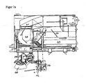
- FIG. 1 a shows the guidance of the suction air and exhaust air of a sweeping vehicle according to the invention.
- the sweeping vehicle has a nozzle assembly which is supported by means of wheels against the road surface.
- the nozzle arrangement comprises the suction shaft 12 and the blowing shaft 14, 12 transport air is sucked together with rubbish by means of the suction chute.
- the blower shaft 14 serves to deliver transport air from the sweeping vehicle to the environment.
- the air is sucked by means of the blower 20.
- the loaded transport air takes the flow pattern shown by the arrows 22.
- the sucked air first flows into the refuse container 30, in which coarser dirt components are separated.
- the air then flows out of the refuse container to the inlet side 21 of the blower 20 and is conveyed from its outlet side into the blowing chute 14, as indicated by dotted arrows.
- the refuse is fed to the inlet of the suction chute 12 by means of the plate insert 40 and the sweeping roller 50, in particular from Figure 1 c can be seen.
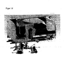
- FIG. 1b shows the upper portion of the blower shaft 14 and the line section 15, by means of which the pressure side of the blower 20 is in communication with the suction side of the blower.
- this line section 15 is the Regulierklappe 16, according to FIG. 1 b, left representation is in the closed position. In this, the entire blower exhaust air flows to the blower shaft 14 and then into the ambient atmosphere. If the flap 16 is opened as shown in FIG Figure 1 b , right representation is shown, the exhaust air flow is divided. It is guided on the one hand into the blowing shaft 14 and then into the environment and on the other hand into the line section 15. The guided through the line section 15 portion of the air is mixed with the supplied via the suction chute 12 suction air and then fed to the container 30 again. In this way, the blower exhaust air is partially recirculated, whereby the cleaning performance of the sweeper is improved, especially with regard to fine dust.
- FIG. 1 a show the arrangement according to FIG. 1 a in different perspective views.
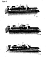
- FIG. 2 shows different views of the sweeping roller 50 of the sweeper according to the invention.
- the broom 50 is pivotally mounted by means of two brackets 52 so that they can be adjusted in their inclination, as is made FIG. 2 showing the sweeping roller 50 in a left-inclined, in a horizontal and a right-angled orientation.
- Each of the brackets 52 has a bore disposed on the tie rod end 54 so that the bracket 52 can be reciprocated about the longitudinal axis of the tie rod end 54.
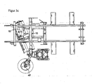
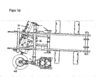
- FIG. 3 shows the disc brush 40 and the sweeping roller 50 of the sweeping vehicle according to the invention in different positions.
- FIG. 3 a shows the disc brush 40 in its parking position, in which this in the raised position below the sweeping vehicle is arranged.
- the sweeping roller 50 is shown in its left-hand position.
- the tie rod 53 can be seen in the head portions 54 according to FIG. 2 the sweeping roller 50 is mounted oscillating, as is the case FIG. 2 was explained.
- the tie rod 53 is pivotable about the vertical axis 55, so that the sweeping roller 50 not only a pendulum motion according to FIG. 2 but also can perform a pivoting movement to the broom from the left position in the in FIG. 3 d to move displayed legal position.
- a guide 56 is provided, which is arranged stationary and on which the tie rod 53 or a guide element arranged on it runs.
- the movement of the sweeping roller 50 or the tie rod 53 can be effected for example by means of a pneumatic cylinder.
- FIG. 3 b shows the disc brush 40 in a pivoted to a first stage position.
- the position of the sweeping roller 50 corresponds to that Figure 3 a explained.
- FIG. 3 c shows the disc brush 40 in its second pivoted-out stage.
- the sweeping roller 50 is still in the in FIG. 3 a position shown.
- FIG. 3 d finally shows the plate broom in its parking position according to Figure 3 a However, the sweeping roller in its right position, in which the tie rod 53 is received in the right stop area.
- the sweeping roller 50 which can be pivoted from left to right or vice versa, has the advantage that it can be used both on unilaterally reciprocating and suctioning machines as well as on both sides sweeping and sucking machines.
- the oscillating arrangement of the sweeping roller has the advantage that its mobility is significantly improved, so that road irregularities can be compensated because the sweeping roller 50 always adapts to the road surface.
- FIG. 4 shows a circuit diagram of the hydraulic control of an embodiment of the sweeping machine according to the invention.
- Both hydraulic pumps are driven by the drive motor of the sweeper, the diesel engine 80.
- they are connected via a propeller shaft 81 and a coupling 82 with this.
- the blower pump 90 forms a closed hydraulic circuit with the turbine engine 101 of the blower and is controlled by a control computer 95 by means of an electromagnet 83.
- the control computer 95 receives rotational speed signals of the diesel engine 80 and of the turbine engine 101 and keeps the desired rotational speed of the turbine engine 101 set via a potentiometer mounted in the driver's cab by a corresponding activation of the turbine pump 91.
- the turbine pump 91 is designed as a variable displacement pump.
- the second hydraulic pump 91 is connected via an open hydraulic circuit with the other hydraulically powered consumers such as. the disc broom and the roller connected.
- a hydraulic block 102 is provided, with which the second hydraulic pump is connected via a pressure line 96, to which in turn the other consumers are connected.
- the hydraulic block 102 has proportional valves and controls the adjustable second hydraulic pump 91 via a line 97.
- the working hydraulics is driven by a conventional LS control.
- a hydraulic oil tank 93 is provided with an oil filter 94 connected to the hydraulic pumps via suction pipes and drain pipes. Also, the hydraulic block 102 is connected via a return line to the hydraulic oil tank. Furthermore, an oil cooler 92 is provided.
Landscapes
- Engineering & Computer Science (AREA)
- Architecture (AREA)
- Civil Engineering (AREA)
- Structural Engineering (AREA)
- Cleaning Of Streets, Tracks, Or Beaches (AREA)
- Cleaning In General (AREA)
- Air Transport Of Granular Materials (AREA)
- Ventilation (AREA)
Claims (37)
- Balayeuse avec un ventilateur (20) avec un système de conduite côté aspiration (12) se trouvant en relation avec le ventilateur (20) dans le sens d'écoulement de l'air de transport en amont du ventilateur (20) et un système de conduite côté pression (14) se trouvant en relation avec le ventilateur (20) dans le sens d'écoulement de l'air de transport en aval du ventilateur (20), le ventilateur (20) se trouvant en relation d'écoulement côté aspiration avec une entrée, par laquelle de l'air de transport est aspirable à partir de l'environnement pendant le fonctionnement du ventilateur et le ventilateur (20) se trouvant en relation d'écoulement côté pression avec une sortie, par laquelle de l'air de transport est évacuable dans l'environnement pendant le fonctionnement du ventilateur (20), le système de conduite côté pression (14) étant reliable ou se trouvant en relation avec le système de conduite côté aspiration, de sorte qu'au moins une partie de l'air se trouvant dans le système de conduite côté pression (12) est introductible dans le système de conduite côté aspiration,
caractérisée en ce que
une section de conduite (15) reliant le système de conduite côté aspiration et celui côté pression (14) est prévue, dans laquelle un volet réglable (16) est prévu, de sorte que la quantité de l'air de transport circulant du système de conduite côté pression dans celui côté aspiration (12) est variable. - Balayeuse selon la revendication 1, caractérisée en ce que le volet (16) est réalisé de sorte que la section de conduite (15) reliant les systèmes de conduite est complètement verrouillable.
- Balayeuse selon les revendications 1 ou 2, caractérisée en ce que le volet (16) est réalisé de sorte que jusqu'à 100 %, de préférence jusqu'à 70 % ou jusqu'à 30 % de l'air vicié du ventilateur est admissible dans le système de conduite côté aspiration.
- Balayeuse selon une quelconque des revendications précédentes, caractérisée en ce que la balayeuse présente une poubelle (30) et en ce que le système de conduite côté pression (14) est reliable ou se trouve en relation avec le système de conduite côté aspiration (12) en amont du bac de la poubelle.
- Balayeuse selon une quelconque des revendications précédentes, caractérisée en ce que la balayeuse présente un ou plusieurs filtres et en ce que le système de conduite côté pression (14) est reliable ou se trouve en relation avec le système de conduite côté aspiration (12) en amont du ou des filtres, ou en cas de plusieurs filtres entre deux filtres.
- Balayeuse selon une quelconque des revendications précédentes, caractérisée en ce que la balayeuse présente un rouleau de balayage (50) qui est disposé de sorte qu'il est oscillant dans une position inclinée par rapport à celle horizontale.
- Balayeuse selon la revendication 6, caractérisée en ce que le rouleau de balayage (50) est disposé de manière mobile pendulaire sur un composant stationnaire ou oscillant de la balayeuse.
- Balayeuse selon la revendication 7, caractérisée en ce que le rouleau de balayage (50) est disposé de manière mobile pendulaire sur une barre d'accouplement disposée de manière oscillante, notamment sur la tête de barre d'accouplement (54) de celui-ci.
- Balayeuse selon une quelconque des revendications précédentes, caractérisée en ce que la balayeuse présente un rouleau de balayage (50) qui est disposé de sorte qu'il est oscillant vers la droite ou vers la gauche par rapport à l'axe longitudinal de la balayeuse.
- Balayeuse selon la revendication 9, caractérisée en ce que le rouleau de balayage (50) se trouve en relation avec une barre d'accouplement qui est oscillante autour d'un axe se trouvant à la verticale ou principalement à la verticale.
- Balayeuse selon une quelconque des revendications précédentes, caractérisée en ce que la balayeuse présente un ou plusieurs groupes qui sont fixés collectivement sur une pièce de support disposée sur le véhicule balayeur, qui se compose d'un tourillon disposé principalement à la verticale, sur lequel une ou plusieurs douilles sont montées sur paliers tournants, sur lesquelles respectivement un ou plusieurs groupes sont fixés.
- Balayeuse selon la revendication 11, caractérisée en ce que pour les groupes, il s'agit d'un balai circulaire (40) et/ou de l'entrée pour l'admission de l'air de transport et/ou de la sortie pour l'évacuation de l'air de transport.
- Balayeuse selon les revendications 11 ou 12, caractérisée en ce que pour le groupe de balayage, il s'agit d'un balai circulaire (40) qui est disposé de manière oscillante autour de deux axes principalement horizontaux et s'étendant transversalement l'un par rapport à l'autre.
- Balayeuse selon la revendication 13, caractérisée en ce que le premier axe s'étend principalement transversalement et en ce que le second axe s'étend principalement longitudinalement par rapport au sens de course de la balayeuse.
- Balayeuse selon les revendications 13 ou 14, caractérisée en ce que le balai circulaire (40) est prétendu dans une position élastique inclinée, dans laquelle il est pivoté autour du premier axe dans le sens de course par rapport à la surface de la route et autour du second axe vers un caniveau ou dans la direction du virage, l'angle d'inclinaison étant limité par des butées.
- Balayeuse selon la revendication 15, caractérisée en ce que le balai circulaire (40) est maintenu sur des coussinets prétendus en caoutchouc soumis aux torsions.
- Balayeuse selon les revendications 15 ou 16, caractérisée par un dispositif destiné au pivotement du balai circulaire (40) autour du second axe en sens inverse de la prétension.
- Balayeuse selon une quelconque des revendications 15 à 17, caractérisée en ce que le balai circulaire (40) est ajustable verticalement pour l'essentiel et alors prétendu élastiquement de sorte qu'en cas d'ajustement vertical suite à des déformations du sol sur la surface de la route, les angles d'inclinaison restent préservés lorsque le balai circulaire (40) touche la surface de la route.
- Balayeuse selon une quelconque des revendications précédentes, caractérisée en ce que la balayeuse présente au moins un balai circulaire (40) avec une suspension pour le balai circulaire (40), qui présente un bras pivotant horizontal pour l'essentiel, pivotable sur le cadre du véhicule autour d'un axe vertical, sur lequel une pièce de tuyau extérieure à axe vertical est fixée, dans lequel une pièce de tuyau intérieure est introduite de manière mobile axialement et non rotative et est déployable et repliable par un vérin pneumatique, et qui présente un axe de support maintenu sur le cadre du véhicule ou une plaque d'appui fixée de préférence sur l'extrémité inférieure de la pièce de tuyau intérieure, sur laquelle le balai circulaire pivotant est maintenu autour de deux axes se croisant, qui peut être extrait sous pression contre une force élastique à partir d'une position de service inclinée autour des deux axes, une plaque d'appui logeant le balai circulaire étant fixée à une extrémité d'un axe de support, dont l'autre extrémité est fixée par un ressort en caoutchouc sur la plaque d'appui ou un élément de maintien.
- Balayeuse selon la revendication 19, caractérisée en ce que sur la plaque d'appui, un moteur de commande est disposé en outre pour le balai circulaire (40).
- Balayeuse selon une quelconque des revendications précédentes, caractérisée en ce que la balayeuse présente une disposition de buses, dont l'admission possède un orifice orienté dans le sens de la conduite et disposé de manière avoisinante à la surface de la route, qui est verrouillable par un deuxième volet fixé de manière articulée sur la disposition de buses, l'axe articulé se produisant de préférence horizontalement étant disposé dans le sens de conduite devant l'orifice et le deuxième volet possédant une paroi courbée autour l'axe articulé, qui verrouille l'orifice à l'état fermé du deuxième volet et est inclinée avec sa zone de bordure tournée vers la surface de la rue dans le sens de la course par rapport à la surface de la route ou se produit parallèlement par rapport à celle-ci et pour ouvrir le deuxième volet autour de l'axe articulé en partant de la surface de la route et de l'orifice vers le haut.
- Balayeuse selon la revendication 21, caractérisée en ce que la paroi courbée s'élargit de manière tangentielle dans la zone supérieure.
- Balayeuse selon les revendications 21 ou 22, caractérisée en ce que la paroi courbée se trouve avec sa section supérieure sur un élément d'étanchéité élastique qui est apposé de manière avoisinante sur la disposition de buse par rapport à la bordure supérieure de l'ouverture.
- Balayeuse selon les revendications 21 ou 23, caractérisée en ce que le deuxième volet est constitué pour l'essentiel comme segment d'un vérin creux, l'axe articulé se produisant pour l'essentiel parallèlement à l'axe du vérin ou coïncide avec celui-ci.
- Balayeuse selon une quelconque des revendications précédentes, caractérisée en ce que la balayeuse présente un moteur de translation pour déplacer la balayeuse ainsi qu'un ou plusieurs outils de travail entraînables hydrauliquement, le groupe des outils de travail entraînables hydrauliquement comprenant le ventilateur (20), le balai circulaire (40) et le rouleau de balayage (50).
- Balayeuse selon la revendication 25, caractérisée en ce que le moteur de translation entraîne au moins une pompe hydraulique (90), à l'aide de laquelle le débit de transport du milieu hydraulique est générable pour l'entraînement des outils de travail.
- Balayeuse selon la revendication 26, caractérisée en ce qu'il s'agit pour au moins la pompe hydraulique (90) d'une pompe à piston axial avec commande de plateau oscillant.
- Balayeuse selon la revendication 25, caractérisée en ce que le moteur de translation entraîne au moins deux pompes hydrauliques (90, 91), à l'aide desquelles deux débits de transport séparés sont générables pour l'entraînement des outils de travail.
- Balayeuse selon la revendication 28, caractérisée en ce que le moteur de translation entraîne une première pompe hydraulique (90) pour l'entraînement du ventilateur ainsi qu'une deuxième pompe hydraulique (91) pour l'entraînement des outils de travail.
- Balayeuse selon la revendication 29, caractérisée en ce qu'un calculateur analogique (95) est prévu pour la commande ou lala régulation de la deuxième pompe hydraulique (90).
- Balayeuse selon la revendication 30, caractérisée en ce qu'un appareil de mesure relatif à la détermination du régime du moteur de translation et un appareil de mesure relatif à la détermination du régime de l'entraînement du ventilateur alimentent le calculateur analogique (95) avec les signaux de régime correspondants.
- Balayeuse selon la revendication 30, caractérisée en ce qu'un élément de réglage est prévu pour la préconisation d'un régime souhaité d'un entraînement de ventilateur sur le calculateur analogique.
- Balayeuse selon la revendication 29, caractérisée en ce qu'une commutation Load-Sensing (commutation LS) est prévue pour la régulation de la deuxième pompe hydraulique (90).
- Procédé destiné au fonctionnement d'une balayeuse selon une quelconque des revendications précédentes, caractérisé en ce qu'au moins une partie de l'air vicié du ventilateur est introduite dans le système de conduite côté aspiration (12).
- Procédé selon la revendication 34, caractérisé en ce que la quantité de l'air de transport conduit dans le circuit peut être modifiée.
- Procédé selon les revendications 34 ou 35, caractérisé en ce que jusqu'à 100 %, de préférence jusqu'à 70 % ou jusqu'à 30 % de l'air aspiré est conduit dans le circuit.
- Procédé selon une quelconque des revendications 34 à 36, caractérisé en ce que l'air vicié du ventilateur conduit dans le circuit est admis en amont de la poubelle (30) dans le système d'aspiration (12).
Priority Applications (2)
| Application Number | Priority Date | Filing Date | Title |
|---|---|---|---|
| SI200631649T SI1780340T1 (sl) | 2005-08-10 | 2006-08-10 | Pometalni stroj in postopek za obratovanje pometalnega stroja |
| PL06016717T PL1780340T3 (pl) | 2005-08-10 | 2006-08-10 | Zamiatarka i sposób eksploatacji zamiatarki |
Applications Claiming Priority (1)
| Application Number | Priority Date | Filing Date | Title |
|---|---|---|---|
| DE102005037866A DE102005037866A1 (de) | 2005-08-10 | 2005-08-10 | Kehrmaschine und Verfahren zum Betrieb einer Kehrmaschine |
Publications (3)
| Publication Number | Publication Date |
|---|---|
| EP1780340A2 EP1780340A2 (fr) | 2007-05-02 |
| EP1780340A3 EP1780340A3 (fr) | 2009-11-18 |
| EP1780340B1 true EP1780340B1 (fr) | 2013-07-03 |
Family
ID=37398654
Family Applications (1)
| Application Number | Title | Priority Date | Filing Date |
|---|---|---|---|
| EP06016717.8A Active EP1780340B1 (fr) | 2005-08-10 | 2006-08-10 | Dispositif de balayage et procédé d'opération associé |
Country Status (7)
| Country | Link |
|---|---|
| EP (1) | EP1780340B1 (fr) |
| DE (1) | DE102005037866A1 (fr) |
| DK (1) | DK1780340T3 (fr) |
| ES (1) | ES2425041T3 (fr) |
| PL (1) | PL1780340T3 (fr) |
| PT (1) | PT1780340E (fr) |
| SI (1) | SI1780340T1 (fr) |
Families Citing this family (3)
| Publication number | Priority date | Publication date | Assignee | Title |
|---|---|---|---|---|
| DE102007013720A1 (de) * | 2007-03-22 | 2008-10-02 | Lobbe Industrieservice Gmbh & Co. Kg | Reinigungssystem für Gleisanlagen |
| DE102021106553A1 (de) * | 2021-03-17 | 2022-09-22 | Faun Viatec Gmbh | Luftreinigungssystem |
| CN116770761B (zh) * | 2023-06-08 | 2024-11-12 | 宁波九龙电讯电机有限公司 | 一种具有压力可调结构的马路清扫机 |
Family Cites Families (5)
| Publication number | Priority date | Publication date | Assignee | Title |
|---|---|---|---|---|
| DE1950865A1 (de) * | 1969-10-09 | 1971-04-29 | Keller & Knappich Gmbh | Lenkarm-Halterung einer Besenwalze in Strassenkehrmaschinen |
| DE4001088C2 (de) * | 1990-01-17 | 1998-09-17 | Smv | Kehrfahrzeug |
| CH687211A5 (de) * | 1993-04-19 | 1996-10-15 | Bucher Guyer Ag Masch | Strassenkehrmaschine mit einem Sauggeblaese. |
| DE29806388U1 (de) * | 1998-03-23 | 1998-08-06 | Faun Müller Umwelttechnik GmbH, 04668 Grimma | Kehrmaschine |
| DE19901873B4 (de) * | 1999-01-19 | 2013-05-29 | Faun Viatec Gmbh | Aufhängung eines Tellerbesens an einem Kehrfahrzeug |
-
2005
- 2005-08-10 DE DE102005037866A patent/DE102005037866A1/de not_active Ceased
-
2006
- 2006-08-10 ES ES06016717T patent/ES2425041T3/es active Active
- 2006-08-10 PT PT60167178T patent/PT1780340E/pt unknown
- 2006-08-10 SI SI200631649T patent/SI1780340T1/sl unknown
- 2006-08-10 DK DK06016717.8T patent/DK1780340T3/da active
- 2006-08-10 PL PL06016717T patent/PL1780340T3/pl unknown
- 2006-08-10 EP EP06016717.8A patent/EP1780340B1/fr active Active
Also Published As
| Publication number | Publication date |
|---|---|
| EP1780340A2 (fr) | 2007-05-02 |
| PT1780340E (pt) | 2013-07-11 |
| EP1780340A3 (fr) | 2009-11-18 |
| DK1780340T3 (da) | 2013-09-30 |
| ES2425041T3 (es) | 2013-10-11 |
| SI1780340T1 (sl) | 2013-10-30 |
| PL1780340T3 (pl) | 2013-12-31 |
| DE102005037866A1 (de) | 2007-02-15 |
Similar Documents
| Publication | Publication Date | Title |
|---|---|---|
| DE3528038C2 (fr) | ||
| DE69307864T2 (de) | Umwandelbare Kehrvorrichtung | |
| DE8709125U1 (de) | Vorrichtung zur Räumung von Verkehrsflächen von Schnee, Schneematsch, Wasser, Schmutz od.dgl. | |
| EP3205774B1 (fr) | Balayeuse | |
| EP1241298B1 (fr) | Véhicule, notamment pour le nettoyage des plages | |
| DE4001088A1 (de) | Kehrfahrzeug | |
| EP0857238B1 (fr) | Balayeuse | |
| EP0197144A1 (fr) | Conduite d'aspiration pour un vehicule d'enlevement de detritus | |
| EP0482293B1 (fr) | Machine pour travailler le sol et train de roues | |
| DE102009047368A1 (de) | Kehranbauvorrichtung für ein Fahrzeug und selbstfahrendes Fahrzeug | |
| DE3604053C2 (fr) | ||
| EP3739126B1 (fr) | Balayeuse autonome | |
| DE2145633A1 (de) | Bodenpflegemaschine | |
| DE10062329C1 (de) | Saug-Kehraggregat | |
| DE202009008719U1 (de) | Kehrmaschine mit einer Kehrwalze | |
| EP1072727B1 (fr) | Véhicule et procédé pour nettoyer les surfaces | |
| EP1780340A2 (fr) | Dispositif de balayage et procédé d'opération associé | |
| WO2017009098A1 (fr) | Machine de nettoyage du sol et procédé pour faire fonctionner une machine de nettoyage du sol | |
| EP1816265B1 (fr) | Balayeuse pour nettoyer des voies, des routes ou surfaces utilisables similaires | |
| EP2192234B1 (fr) | Véhicule de nettoyage | |
| DE4128879A1 (de) | Verfahren zur reinigung von strassenoberflaechen oder dergleichen mit einem kehrfahrzeug sowie kehrfahrzeug | |
| EP0668401A1 (fr) | Balayeuse | |
| DE9415472U1 (de) | Fahrbare Vorrichtung für die Reinigung und Pflege großflächiger Bereiche | |
| EP1612335A2 (fr) | Dispositif de balayage automobile | |
| DE8915800U1 (de) | Sammelgut-Behälter mit flexibler Rohrleitung |
Legal Events
| Date | Code | Title | Description |
|---|---|---|---|
| PUAI | Public reference made under article 153(3) epc to a published international application that has entered the european phase |
Free format text: ORIGINAL CODE: 0009012 |
|
| AK | Designated contracting states |
Kind code of ref document: A2 Designated state(s): AT BE BG CH CY CZ DE DK EE ES FI FR GB GR HU IE IS IT LI LT LU LV MC NL PL PT RO SE SI SK TR |
|
| AX | Request for extension of the european patent |
Extension state: AL BA HR MK YU |
|
| PUAL | Search report despatched |
Free format text: ORIGINAL CODE: 0009013 |
|
| AK | Designated contracting states |
Kind code of ref document: A3 Designated state(s): AT BE BG CH CY CZ DE DK EE ES FI FR GB GR HU IE IS IT LI LT LU LV MC NL PL PT RO SE SI SK TR |
|
| AX | Request for extension of the european patent |
Extension state: AL BA HR MK RS |
|
| 17P | Request for examination filed |
Effective date: 20100209 |
|
| 17Q | First examination report despatched |
Effective date: 20100331 |
|
| AKX | Designation fees paid |
Designated state(s): AT BE BG CH CY CZ DE DK EE ES FI FR GB GR HU IE IS IT LI LT LU LV MC NL PL PT RO SE SI SK TR |
|
| GRAP | Despatch of communication of intention to grant a patent |
Free format text: ORIGINAL CODE: EPIDOSNIGR1 |
|
| GRAS | Grant fee paid |
Free format text: ORIGINAL CODE: EPIDOSNIGR3 |
|
| GRAA | (expected) grant |
Free format text: ORIGINAL CODE: 0009210 |
|
| AK | Designated contracting states |
Kind code of ref document: B1 Designated state(s): AT BE BG CH CY CZ DE DK EE ES FI FR GB GR HU IE IS IT LI LT LU LV MC NL PL PT RO SE SI SK TR |
|
| REG | Reference to a national code |
Ref country code: GB Ref legal event code: FG4D Free format text: NOT ENGLISH |
|
| REG | Reference to a national code |
Ref country code: PT Ref legal event code: SC4A Free format text: AVAILABILITY OF NATIONAL TRANSLATION Effective date: 20130704 |
|
| REG | Reference to a national code |
Ref country code: AT Ref legal event code: REF Ref document number: 619864 Country of ref document: AT Kind code of ref document: T Effective date: 20130715 Ref country code: CH Ref legal event code: NV Representative=s name: KELLER AND PARTNER PATENTANWAELTE AG, CH Ref country code: CH Ref legal event code: EP |
|
| REG | Reference to a national code |
Ref country code: IE Ref legal event code: FG4D Free format text: LANGUAGE OF EP DOCUMENT: GERMAN |
|
| REG | Reference to a national code |
Ref country code: DE Ref legal event code: R096 Ref document number: 502006012975 Country of ref document: DE Effective date: 20130829 |
|
| REG | Reference to a national code |
Ref country code: SE Ref legal event code: TRGR Ref country code: RO Ref legal event code: EPE |
|
| REG | Reference to a national code |
Ref country code: DK Ref legal event code: T3 Effective date: 20130925 Ref country code: DK Ref legal event code: T3 |
|
| REG | Reference to a national code |
Ref country code: ES Ref legal event code: FG2A Ref document number: 2425041 Country of ref document: ES Kind code of ref document: T3 Effective date: 20131011 |
|
| REG | Reference to a national code |
Ref country code: NL Ref legal event code: T3 |
|
| REG | Reference to a national code |
Ref country code: SK Ref legal event code: T3 Ref document number: E 14864 Country of ref document: SK |
|
| REG | Reference to a national code |
Ref country code: LT Ref legal event code: MG4D |
|
| REG | Reference to a national code |
Ref country code: PL Ref legal event code: T3 |
|
| PG25 | Lapsed in a contracting state [announced via postgrant information from national office to epo] |
Ref country code: LT Free format text: LAPSE BECAUSE OF FAILURE TO SUBMIT A TRANSLATION OF THE DESCRIPTION OR TO PAY THE FEE WITHIN THE PRESCRIBED TIME-LIMIT Effective date: 20130703 Ref country code: CY Free format text: LAPSE BECAUSE OF FAILURE TO SUBMIT A TRANSLATION OF THE DESCRIPTION OR TO PAY THE FEE WITHIN THE PRESCRIBED TIME-LIMIT Effective date: 20130717 Ref country code: IS Free format text: LAPSE BECAUSE OF FAILURE TO SUBMIT A TRANSLATION OF THE DESCRIPTION OR TO PAY THE FEE WITHIN THE PRESCRIBED TIME-LIMIT Effective date: 20131103 |
|
| PG25 | Lapsed in a contracting state [announced via postgrant information from national office to epo] |
Ref country code: LV Free format text: LAPSE BECAUSE OF FAILURE TO SUBMIT A TRANSLATION OF THE DESCRIPTION OR TO PAY THE FEE WITHIN THE PRESCRIBED TIME-LIMIT Effective date: 20130703 Ref country code: GR Free format text: LAPSE BECAUSE OF FAILURE TO SUBMIT A TRANSLATION OF THE DESCRIPTION OR TO PAY THE FEE WITHIN THE PRESCRIBED TIME-LIMIT Effective date: 20131004 |
|
| PG25 | Lapsed in a contracting state [announced via postgrant information from national office to epo] |
Ref country code: CY Free format text: LAPSE BECAUSE OF FAILURE TO SUBMIT A TRANSLATION OF THE DESCRIPTION OR TO PAY THE FEE WITHIN THE PRESCRIBED TIME-LIMIT Effective date: 20130703 |
|
| PG25 | Lapsed in a contracting state [announced via postgrant information from national office to epo] |
Ref country code: EE Free format text: LAPSE BECAUSE OF FAILURE TO SUBMIT A TRANSLATION OF THE DESCRIPTION OR TO PAY THE FEE WITHIN THE PRESCRIBED TIME-LIMIT Effective date: 20130703 Ref country code: MC Free format text: LAPSE BECAUSE OF FAILURE TO SUBMIT A TRANSLATION OF THE DESCRIPTION OR TO PAY THE FEE WITHIN THE PRESCRIBED TIME-LIMIT Effective date: 20130703 |
|
| PLBE | No opposition filed within time limit |
Free format text: ORIGINAL CODE: 0009261 |
|
| STAA | Information on the status of an ep patent application or granted ep patent |
Free format text: STATUS: NO OPPOSITION FILED WITHIN TIME LIMIT |
|
| 26N | No opposition filed |
Effective date: 20140404 |
|
| REG | Reference to a national code |
Ref country code: DE Ref legal event code: R097 Ref document number: 502006012975 Country of ref document: DE Effective date: 20140404 |
|
| REG | Reference to a national code |
Ref country code: AT Ref legal event code: MM01 Ref document number: 619864 Country of ref document: AT Kind code of ref document: T Effective date: 20130810 |
|
| PG25 | Lapsed in a contracting state [announced via postgrant information from national office to epo] |
Ref country code: AT Free format text: LAPSE BECAUSE OF NON-PAYMENT OF DUE FEES Effective date: 20130810 |
|
| REG | Reference to a national code |
Ref country code: CH Ref legal event code: PCAR Free format text: NEW ADDRESS: EIGERSTRASSE 2 POSTFACH, 3000 BERN 14 (CH) |
|
| PG25 | Lapsed in a contracting state [announced via postgrant information from national office to epo] |
Ref country code: HU Free format text: LAPSE BECAUSE OF FAILURE TO SUBMIT A TRANSLATION OF THE DESCRIPTION OR TO PAY THE FEE WITHIN THE PRESCRIBED TIME-LIMIT; INVALID AB INITIO Effective date: 20060810 |
|
| PG25 | Lapsed in a contracting state [announced via postgrant information from national office to epo] |
Ref country code: BE Free format text: LAPSE BECAUSE OF NON-PAYMENT OF DUE FEES Effective date: 20160831 |
|
| REG | Reference to a national code |
Ref country code: FR Ref legal event code: PLFP Year of fee payment: 11 |
|
| PG25 | Lapsed in a contracting state [announced via postgrant information from national office to epo] |
Ref country code: BE Free format text: LAPSE BECAUSE OF NON-PAYMENT OF DUE FEES Effective date: 20160831 |
|
| PGRI | Patent reinstated in contracting state [announced from national office to epo] |
Ref country code: BE Effective date: 20170214 |
|
| REG | Reference to a national code |
Ref country code: FR Ref legal event code: PLFP Year of fee payment: 12 |
|
| PG25 | Lapsed in a contracting state [announced via postgrant information from national office to epo] |
Ref country code: BG Free format text: LAPSE BECAUSE OF NON-PAYMENT OF DUE FEES Effective date: 20190430 |
|
| PGFP | Annual fee paid to national office [announced via postgrant information from national office to epo] |
Ref country code: SK Payment date: 20190729 Year of fee payment: 14 Ref country code: SI Payment date: 20190729 Year of fee payment: 14 Ref country code: IE Payment date: 20190826 Year of fee payment: 14 Ref country code: PT Payment date: 20190729 Year of fee payment: 14 Ref country code: SE Payment date: 20190826 Year of fee payment: 14 |
|
| REG | Reference to a national code |
Ref country code: CH Ref legal event code: PFA Owner name: FAUN VIATEC GMBH, DE Free format text: FORMER OWNER: FAUN VIATEC GMBH, DE |
|
| REG | Reference to a national code |
Ref country code: SE Ref legal event code: EUG |
|
| REG | Reference to a national code |
Ref country code: SK Ref legal event code: MM4A Ref document number: E 14864 Country of ref document: SK Effective date: 20200810 |
|
| PG25 | Lapsed in a contracting state [announced via postgrant information from national office to epo] |
Ref country code: PT Free format text: LAPSE BECAUSE OF NON-PAYMENT OF DUE FEES Effective date: 20210310 |
|
| PG25 | Lapsed in a contracting state [announced via postgrant information from national office to epo] |
Ref country code: SE Free format text: LAPSE BECAUSE OF NON-PAYMENT OF DUE FEES Effective date: 20200811 |
|
| PG25 | Lapsed in a contracting state [announced via postgrant information from national office to epo] |
Ref country code: SK Free format text: LAPSE BECAUSE OF NON-PAYMENT OF DUE FEES Effective date: 20200810 |
|
| PG25 | Lapsed in a contracting state [announced via postgrant information from national office to epo] |
Ref country code: SI Free format text: LAPSE BECAUSE OF NON-PAYMENT OF DUE FEES Effective date: 20200811 Ref country code: IE Free format text: LAPSE BECAUSE OF NON-PAYMENT OF DUE FEES Effective date: 20200810 |
|
| PGFP | Annual fee paid to national office [announced via postgrant information from national office to epo] |
Ref country code: NL Payment date: 20210823 Year of fee payment: 16 Ref country code: LU Payment date: 20210823 Year of fee payment: 16 |
|
| PGFP | Annual fee paid to national office [announced via postgrant information from national office to epo] |
Ref country code: FI Payment date: 20210819 Year of fee payment: 16 |
|
| REG | Reference to a national code |
Ref country code: SI Ref legal event code: KO00 Effective date: 20210901 |
|
| PGFP | Annual fee paid to national office [announced via postgrant information from national office to epo] |
Ref country code: RO Payment date: 20210802 Year of fee payment: 16 |
|
| REG | Reference to a national code |
Ref country code: NL Ref legal event code: MM Effective date: 20220901 |
|
| PG25 | Lapsed in a contracting state [announced via postgrant information from national office to epo] |
Ref country code: RO Free format text: LAPSE BECAUSE OF NON-PAYMENT OF DUE FEES Effective date: 20220810 Ref country code: LU Free format text: LAPSE BECAUSE OF NON-PAYMENT OF DUE FEES Effective date: 20220810 Ref country code: FI Free format text: LAPSE BECAUSE OF NON-PAYMENT OF DUE FEES Effective date: 20220810 |
|
| PG25 | Lapsed in a contracting state [announced via postgrant information from national office to epo] |
Ref country code: NL Free format text: LAPSE BECAUSE OF NON-PAYMENT OF DUE FEES Effective date: 20220901 |
|
| P01 | Opt-out of the competence of the unified patent court (upc) registered |
Effective date: 20230602 |
|
| PGFP | Annual fee paid to national office [announced via postgrant information from national office to epo] |
Ref country code: ES Payment date: 20250917 Year of fee payment: 20 |
|
| PGFP | Annual fee paid to national office [announced via postgrant information from national office to epo] |
Ref country code: DK Payment date: 20250821 Year of fee payment: 20 Ref country code: DE Payment date: 20250819 Year of fee payment: 20 |
|
| PGFP | Annual fee paid to national office [announced via postgrant information from national office to epo] |
Ref country code: TR Payment date: 20250805 Year of fee payment: 20 Ref country code: PL Payment date: 20250725 Year of fee payment: 20 Ref country code: IT Payment date: 20250829 Year of fee payment: 20 |
|
| PGFP | Annual fee paid to national office [announced via postgrant information from national office to epo] |
Ref country code: BE Payment date: 20250820 Year of fee payment: 20 Ref country code: GB Payment date: 20250822 Year of fee payment: 20 |
|
| PGFP | Annual fee paid to national office [announced via postgrant information from national office to epo] |
Ref country code: FR Payment date: 20250827 Year of fee payment: 20 |
|
| PGFP | Annual fee paid to national office [announced via postgrant information from national office to epo] |
Ref country code: CH Payment date: 20250901 Year of fee payment: 20 |
|
| PGFP | Annual fee paid to national office [announced via postgrant information from national office to epo] |
Ref country code: CZ Payment date: 20250729 Year of fee payment: 20 |