EP1780348A2 - Élément préfabriqué pour fabrication d'un élément de construction - Google Patents
Élément préfabriqué pour fabrication d'un élément de construction Download PDFInfo
- Publication number
- EP1780348A2 EP1780348A2 EP06120337A EP06120337A EP1780348A2 EP 1780348 A2 EP1780348 A2 EP 1780348A2 EP 06120337 A EP06120337 A EP 06120337A EP 06120337 A EP06120337 A EP 06120337A EP 1780348 A2 EP1780348 A2 EP 1780348A2
- Authority
- EP
- European Patent Office
- Prior art keywords
- layer
- prefabricated component
- concrete
- geomembrane
- component according
- Prior art date
- Legal status (The legal status is an assumption and is not a legal conclusion. Google has not performed a legal analysis and makes no representation as to the accuracy of the status listed.)
- Withdrawn
Links
Images

Classifications
-
- E—FIXED CONSTRUCTIONS
- E04—BUILDING
- E04C—STRUCTURAL ELEMENTS; BUILDING MATERIALS
- E04C2/00—Building elements of relatively thin form for the construction of parts of buildings, e.g. sheet materials, slabs, or panels
- E04C2/02—Building elements of relatively thin form for the construction of parts of buildings, e.g. sheet materials, slabs, or panels characterised by specified materials
- E04C2/04—Building elements of relatively thin form for the construction of parts of buildings, e.g. sheet materials, slabs, or panels characterised by specified materials of concrete or other stone-like material; of asbestos cement; of cement and other mineral fibres
- E04C2/044—Building elements of relatively thin form for the construction of parts of buildings, e.g. sheet materials, slabs, or panels characterised by specified materials of concrete or other stone-like material; of asbestos cement; of cement and other mineral fibres of concrete
Definitions
- the invention relates to a prefabricated component with a multilayer structure for producing a structural part. Furthermore, the invention relates to a method for producing such a prefabricated component.
- Prefabricated components are known for producing watertight and pressure-tight structural parts comprising a concrete wall and a heat-insulating wall, wherein on the side facing the concrete wall of the heat-insulating wall there is a layer of bitumen in contact with the concrete wall.
- These prefabricated components are used in particular for building basements as a basement wall.
- the height of such a basement wall is preferably a storey height.
- Such a basement wall is for example from the German utility model DE 20 2004 005 037 U1 known.
- a watertight, in particular a watertight, connection of bituminous layers of two adjacent prefabricated components is relatively complicated.
- no heat-insulating wall can be formed in the adjacent region of a joint between two prefabricated components before joining the bituminous layers, so that after joining two adjacent wall elements, the prefabricated components still need to be provided later on the site with a heat-insulating wall, so that a closed thermal insulation of the outer basement walls is formed.
- it is relatively complicated to safely and permanently connect the two bitumen layers of adjacent prefabricated components to one another in a watertight manner.
- the subsequent sealing leaks is relatively complex in such a structure of a prefabricated, since the thermal barrier must be removed to search for these leaks.
- a complicating factor is that the heat-insulating wall is provided on the side facing the concrete wall for sealing the structure with a layer of bitumen.
- the object of the invention is to provide a prefabricated component for producing a structural part, which has a simple structure and is easy to manufacture. Furthermore, a method for producing such a finished component is to be specified.
- a simple access to this geomembrane is possible in particular by the geomembrane layer arranged on the outside of the thermal barrier layer, wherein the geomembrane can be connected in a simple manner with geomembranes preferably more uniformly to the prefabricated component abutting prefabricated components. Furthermore, the thermal insulation of the thermal barrier coating is increased by the externally arranged sealing membrane, since no moisture can penetrate into the thermal barrier coating and reduce the thermal insulation.
- the insulating material is applied to the inside of the geomembrane, so that a permanent tight connection between the geomembrane and the thermal barrier coating is produced.
- the thermal barrier coating is poured with the aid of Ortschaum on the geomembrane or on the Geomembrane sprayed. Such a connection can only be solved by destroying the geomembrane and / or the thermal barrier coating.
- edges of the prefabricated component may preferably be formed in abutting areas with adjacent prefabricated components such that the thermal barrier coating, the waterproofing membrane and / or the concrete layer protrudes from at least one of the other layers, so that a part of the concrete layer and / or a part of the thermal barrier coating to the concrete layer or the thermal barrier coating of the adjacent precast abuts.
- a second aspect of the invention relates to a method for producing a prefabricated component in which a sealing layer forming a first layer is inserted into an upwardly open mold delimiting the prefabricated component to be produced, wherein the surface of the geomembrane forming the outside of the prefabricated component contacts the underside of the mold.
- a thermal barrier coating is applied on the inside of the inserted in the form geomembrane .
- a concrete-containing layer is applied to the local foam in the mold.
- a prefabricated component according to claim 1 is simple and inexpensive to manufacture.
- the geomembrane is integrally formed so as to cover the entire bottom surface of the mold.
- suitable connection means can be provided.
- the adhesive layer may contain a mineral adhesive, a plastic adhesive and / or a resin adhesive.
- a third aspect of the invention relates to a second method for producing a prefabricated component, in which a layer comprising concrete is introduced into an upwardly open mold delimiting the prefabricated component to be produced.
- a thermal barrier coating is applied to the concrete layer in the form.
- a geomembrane is applied to the preferably not or not yet fully hardened local foam.
- Polysterolplatten be used to form the thermal barrier coating, which in a simple manner, a planar arrangement of the geomembrane 22 is possible on these insulation boards.
- An adhesive layer is then preferably provided between the insulating panels and the geomembrane.
- the surface of the concrete containing layer Prior to applying the topping foam layer to the concrete containing layer, the surface of the concrete containing layer should be roughened by suitable means to improve the adhesion of the topping foam to the surface of the concrete containing layer and hence the bond between the concrete containing layer and the thermal barrier coating.
- a simple and secure connection is produced both between the geomembrane and the thermal barrier coating and between the thermal barrier coating and the concrete layer.
- the finished component consisting of the at least three layers can be easily transported and assembled on site with other similar components.
- the geomembrane arranged on the outside allows the geomembrane to be easily connected to other sealing elements of the building part.
- the geomembrane can survive on at least one side of the prefabricated component on the thermal barrier coating and / or concrete layer.
- the concrete-containing layer preferably contains reinforcing agents, in particular reinforcing steel.
- the concrete-containing layer with or without possible in this Layer further agents will hereinafter generally referred to as a concrete layer.
- a fourth aspect of the invention relates to the use of a prefabricated component according to the invention with at least one further prefabricated component connected to the prefabricated component for producing a liquid-tight container.
- a liquid-tight container is in particular a cellar or a basin.
- the geomembrane is arranged on the outside of the basement and the concrete-containing layer on the inside of the basement.
- the geomembrane on the inside of the basin and the concrete layer is disposed on the outside of the basin.
- At least one further layer, in particular for the mechanical protection of the sealing web can be arranged in each case on the outside of the prefabricated component formed by the geomembrane and on the outside of the prefabricated component comprising the concrete.
- FIG. 1 shows a sectional view of a detail of a building part 10 according to a first embodiment of the invention, which contains a horizontally arranged base plate 12 and a prefabricated component 14 arranged vertically in the edge region of the base plate 12.
- This building part 10 is in the present embodiment, a basement, are built on the following more floors.
- At the outer end faces of the bottom plate 12 is circumferentially a multi-layer joint tape 13 molded from a plastic.
- the bottom plate 12 has preferably been produced locally with the aid of in-situ concrete, wherein the concrete used is preferably steel-reinforced water-impermeable concrete.
- the prefabricated component 14 comprises a steel-reinforced concrete layer 16.
- the prefabricated component 14 comprises a heat-insulating layer 18, which is connected to the concrete layer 16 via an adhesive layer 20.
- the prefabricated component 14 further comprises a geomembrane 22, on the inside, i. on the heat-insulating layer 18 side facing a laminated non-woven layer 24 is present.
- a geomembrane 22 is also referred to as fleece-laminated geomembrane 22.
- the geomembrane 22 itself is a plastic sealing strip with a layer thickness of preferably 2 mm or 2.5 mm, which is formed in two layers with a glass fleece insert.
- the thermal barrier coating 18 is made of a polyurethane foam which is poured or sprayed onto the nonwoven layer 24 of the geomembrane 22 in the liquid state. Furthermore, plastic anchors 25a, 25b with barbs 26a, 26b are glued to the nonwoven layer 24 of the sealing sheet 22 with the aid of a suitable adhesive. In particular, the plastic anchors 25a, 25b can be glued to the nonwoven layer 24 of the geomembrane 22 with the aid of the polyurethane foam.
- the plastic anchors 25a, 25b are substantially perpendicular from the inside of the geomembrane 22 and have a length through which a part of the plastic anchors 25a, 25b protrude through the thermal barrier coating 18 into the concrete layer 16.
- the plastic anchors 25a, 25b have laterally projecting barbs 26a, 26b, which prevent the respective plastic anchor 25a, 25b from being pulled out of the concrete layer 16.
- the plastic anchors 25a, 25b and the adhesive layer 20 thus ensure a secure connection between the thermal barrier coating 18 and the concrete layer 16.
- the prefabricated component 14 serves as an outer wall element of the basement to be built and is placed on a recess provided on the edge of the bottom plate 12.
- connecting means for connecting the bottom plate 12 to the prefabricated part 14 are provided.
- an epoxy resin in particular by compression with epoxy resin introduced.
- a mortar joint or a mineral adhesive in the joint area between the recess 28 of the bottom plate 12 and the concrete wall 16 may be provided.
- the introduction of force into the base plate 12 thus takes place through the recess 28, also referred to as a rebate, in the base plate 12.
- the recess 28 may contain one or more steel components 29.
- a steel profile, preferably an L-profile may be provided circumferentially in the recess 28.
- a further steel component may be provided on the underside and / or in the lower region of the inside of the prefabricated component 14, wherein the steel components are connected to one another at least in a partial region by means of sealing means and / or by welding.
- the steel component 29 is preferably embedded in the recess 28 made by a recess 28 of the bottom plate 12, wherein the steel insert member 29 is fixed to the bottom plate 12.
- the steel component preferably provided on the prefabricated component 14 is already connected to the introduction of the concrete layer 16 by setting this concrete layer 16 during the production of the prefabricated component 14.
- the preparation of the recess 28 in the bottom plate 12 is preferably carried out by introducing a squared timber or other suitable element on top of the bottom plate 12 during manufacture.
- the recess 28 has a depth in the range between 3 cm and 5 cm. Preferably, it is designed as a 5 cm deep fold. Through this depression, the horizontal loads are safely introduced into the bottom plate 12 through this depression. The horizontal loads result from the forces in the earth filling of the basement and by the then permanently existing earth pressure and the presence of ground or surface water, the water pressure of the outside of the basement upcoming water.
- the polyurethane thermal barrier coating 18 has a layer thickness of 100 mm and the steel-reinforced concrete layer 16 has a thickness of 140 mm, whereby a total thickness of the finished component 14 of about 240 mm is achieved.
- a floor structure 30 is provided, which in particular comprises a thermal barrier layer and a screed layer, wherein, in particular, dry screed elements can be used for producing the floor structure.
- the bottom plate 12 can also be thermally insulated on the underside.
- the bottom plate 12 When erecting the basement, the bottom plate 12 is first preferably made on site. The cell wall forming precast component 14 is then placed on the bottom plate 12.
- the prefabricated component 14 is, as already described, connected to the base plate 12 and to adjacent prefabricated components 14.
- at least four prefabricated components 14 are used for erecting the walls of a rectangular basement, one prefabricated component 14 for each side of the rectangular basement.
- the prefabricated components 14 may also be L-shaped so that one corner of the structural component 10 is already prefabricated by a prefabricated component 14 is and the connection between adjacent prefabricated components 14 then preferably takes place on one side of the basement.
- Other forms of prefabricated component 14 are possible and are essentially limited only by the available transport options.
- pressure-tight light shafts can also be molded or attached to the prefabricated component 14.
- reinforcement connections may be provided, whereby the respective components 12, 14 are connected by subsequent Betonverguss.
- a welded connection can also be provided, wherein steel elements provided on the finished part 14 and on the base plate 12 as well as steel elements provided on the prefabricated components 14 are welded together.
- the multi-layer joint tape 13, which forms the edge termination of the bottom plate 12 is watertight connected by the molded and cast into the concrete of the bottom plate 12 webs with the bottom plate 12.
- a sealing strip 32 is connected both to the outside of the sealing membrane 22 and to the outside of the joint tape 13.
- This connection is preferably produced by means of hot air welding, chemical welding or gluing.
- a watertight connection between the joint tape 13 and the geomembrane 22 is achieved.
- Such a connection between the geomembrane 22 and the joint strip 13 by means of the sealing web strip 32 is circumferentially around the basement, so that a watertight connection between the bottom plate 12 and the prefabricated components 14 of the cellar takes place.
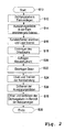
- FIG. 2 shows a flowchart with method steps for producing the basement wall as prefabricated component 14 in a prefabricated building.
- the process is started in step S10.
- step S12 the geomembrane 22 is placed with its outside down in a shape that limits the prefabricated part 14.
- the nonwoven layer 24 points upwards.
- the geomembrane 22 may be fixed to the bottom of the mold by any suitable means, in particular by means of vacuum, adhesive or other suitable means.
- the geomembrane 22 has preferably been unrolled from a roll having a width corresponding to the height of the prefabricated component 14 and cut to the length of the prefabricated component 14.
- the geomembrane 22 may be one of the widths of the prefabricated component 14 have corresponding width, wherein the sealing sheet 22 is unrolled from the roll and cut to a height corresponding to the height of the prefabricated component 14 and inserted into the mold. Then, in step S14, recess boxes are arranged on the sealing sheet 22, through which recesses, in particular for window openings and pipe penetrations as well as for cable bushings, are required.
- the recess boxes have a height which corresponds at least to the wall thickness of the prefabricated component 14 to be produced.
- the width of the geomembrane 22 is less than the height of the prefabricated component 14, the geomembrane 22 then covering only the height of the prefabricated component 14 to be sealed.
- the thermal barrier coating 16 is applied over the entire height of the prefabricated component 14.
- the geomembrane 22 preferably extends at least from the underside of the prefabricated component 14 to the underside of the lowest basement window or to the upper edge of the ground after completion of the building. From the upper edge of the geomembrane 22 to the upper edge of the prefabricated component 14, instead of the geomembrane 22, a cost-effective foil can be used, which in particular forms an insulating layer between the bottom of the mold and the thermal barrier coating 16. For example, therefore, a PE film is suitable.
- plastic anchors 25a, 25b with their plate-shaped back are placed on the nonwoven layer 24 of the sealing membrane 22.
- these plastic anchors 25a, 25b can also be fixed in position by means of a suitable adhesive or another bonding agent on the inside of the sealing membrane 22 or on the nonwoven layer 24. This is particularly advantageous for fixing the position of the plastic anchors 25 during the subsequent introduction of the thermal barrier coating 18 carried out in step S18.
- the rod-shaped plastic anchors 25a, 25b with the barbs 26a, 26b arranged in the front region of the plastic anchors 25a, 25b thus project upwardly from the inside of the sealing membrane 22 in the form of the prefabricated component 14.
- step S18 the thermal barrier coating 18 is poured or injected into the mold in the form of local foam, so that a thermal barrier coating 18 with substantially the same layer thickness is produced on the inside of the waterproofing membrane 22.
- the liquid local foam of the nonwoven layer 24 connects by the local foam at least partially penetrates into the nonwoven layer 24.
- the geomembrane 22 and the thermal barrier coating 18 are integrally connected.
- this processing step S 22 are at least the barbs 26a, 26b of the plastic anchors 25a, 25b from the thermal barrier coating 18 upwards.
- the thermal barrier coating 18 After hardening of the local foam of the thermal barrier coating 18 reinforcing elements, in particular steel mats and / or the reinforcing iron in the form above the thermal barrier coating 18 are arranged so that they sufficient to be generated on the thermal barrier coating 18 concrete layer 16 for the building with the help of the prefabricated structure 14 sufficient reinforce.
- the reinforcement can be arranged in the mold before the introduction of the local foam of the thermal barrier coating 18. The reinforcement can for example be held at least partially by the plastic anchors 25a, 25b.
- step S20 a layer 20 of adhesive is applied to the hardened local foam of the thermal barrier coating 18.
- This adhesive layer 20 may in particular comprise a further local foam layer or alternatively or additionally a mineral adhesive, a plastic adhesive and / or a resin adhesive. be generated.
- step S22 fresh concrete is introduced into the mold on the not yet or not yet completely hardened adhesive layer 20.
- the prefabricated component 14 is separated from the mold in step S24, preferably by removing the edge form of the mold and the component 14 from the bottom of the mold.
- the underside of the mold is preferably formed by a formwork table.
- the recess boxes are removed in step S26 and provided for these recesses internals, such as pipe penetrations, cable glands or windows installed.
- the sealing sheet 22 is opened in step S28 and welded with suitable connection seals and / or connected to connection profiles.
- step S30 the process is ended.
- a flat and wrinkle-free embodiment of the geomembrane 22 on the outside of the prefabricated component 14 is an optimal prerequisite for a watertight sealing of the cellar.
- the compression of the geomembranes 22 a plurality of adjacent prefabricated components 14 is greatly facilitated by the planar arrangement of the geomembrane 22 on the prefabricated component 14, whereby the production of a tight connection in high quality is simplified.
- the flat and wrinkle-free arrangement of the geomembrane 22 is achieved in particular by the insertion of the geomembrane 22 into the mold on its flat underside.
- the individual layers 16, 18, 22 can be introduced into the mold in an inverted sequence.
- the concrete layer and possibly required in the concrete layer reinforcement as the first layer 16 is introduced into the mold.
- insulating boards 18 are applied to form the thermal barrier coating 18 on the concrete layer.
- the insulation boards can be pressed into the still liquid concrete and connected by setting the concrete with this or alternatively connected by means of an additional adhesive layer between the concrete layer 16 and the insulation boards with the concrete layer 16.
- the sealing sheet 22 is glued with the aid of a suitable adhesive to the thermal insulation panels of the thermal barrier coating 18.
- the thermal insulation boards are, for example, polystyrene, Styrodur and / or other suitable insulation boards.
- basement walls must accommodate a variety of loads.
- the basement walls have vertical loads of the basement ceiling and the building erected on the basement ceiling and horizontal loads generated by Erdan Strukturllungen and upcoming groundwater.
- Basement walls generally have a two-layer steel reinforcement, wherein the wall thickness of the concrete layer 16 can be reduced to about 14 cm by the structure of the prefabricated component 14 according to the invention.
- the prefabricated component 14 in particular for the construction of swimming pools or containers, smaller wall thicknesses of the concrete layer 16 may be sufficient.
- the wall thickness of the concrete layer 16 depends on the static, but a minimum concrete cover of the reinforcement is required, whereby wall thicknesses of ⁇ 8 cm can be used meaningfully.
- the prefabricated component 14 has a polyurethane thermal barrier coating 18.
- the polyurethane thermal barrier coating 18 is applied in the described manufacturing method of the finished component 14 in liquid form as a two-component mixture on the geomembrane 22.
- a thermal barrier coating 18 with a thickness of 6 cm to 20 cm is applied to the geomembrane 22.
- the thermal barrier coating 18 may also be substantially thinner and be only a few millimeters, the thermal barrier coating 18 then serving essentially for the connection between the geomembrane 22 and the concrete layer 16. The thermal barrier coating 18 then acts as an adhesive layer.
- the geomembrane 22 generally prevents the penetration of water or other liquids.
- plastic waterproofing membranes with a thickness of ⁇ 2 mm can be used advantageously. These plastic sealing sheets can be easily processed and can be easily connected to each other by means of sealing strip 32 by a sealing sheet strip 32 is welded or glued to each of two adjacent sealing sheets 22.
- the total wall thickness of the prefabricated component 14 is for example 24 cm.
- the prefabricated components can have a wall height of usually up to 3 m and a preferably wall length of more than 5 m.
- the maximum wall length is limited by existing transport options and should not or not significantly exceed 13 m for a cost-effective transport.
- the pre-fabricated prefabricated components are then transported to the construction site with the help of a truck and assembled there.
- the invention is not limited to the dimensions given.
- the plastic sealing strip used as sealing sheet 22 is produced by co-extrusion as a two-layer sheet, preferably with a centrally arranged glass fleece of, for example, 50 g / m 2 .
- the plastic sealing sheet is made of an ethylene copolymer and has a commercial thickness of 2.0 mm or 2.5 mm.
- the plastic waterproofing membrane is impermeable to liquids and chemically resistant to liquids such as power water, sulphate-containing ground and surface water and water with chlorine additives. Furthermore, such a plastic waterproofing membrane is resistant to aging and weathering, microorganism resistant, root resistant and rodent resistant. Thus, such plastic waterproofing membranes are also suitable as a sealant of drip pans, catch basins and basements.
- an additional nonwoven 24 is laminated on the inside of the plastic sealing strip, which is used in an embodiment of the present invention for connection to the thermal barrier coating 18.
- the plastic sealing strip 22 is produced as a roll product with a width of, for example, 2 m and a variable roll length. But there are also larger roller widths available and can be used advantageously. Preferably, the roller width corresponds at least to the height of the prefabricated component 14 Plastic sealing sheet is then cut according to the length of the prefabricated component 14. It can be provided that the plastic sealing strip projects beyond at least one side over at least one wider layer 16, 18 of the prefabricated component 14 and forms a connection region to form a further component 14.
- no fleece layer 24 is provided on the reverse side of the geomembrane 22, so that this protruding region can be welded directly onto an adjacent plastic waterproofing membrane 22 or another sealing element, such as the joint tape 13.
- no fleece layer 24 is laminated on the inside of the geomembrane 22.
- the plastic sealing strip 22 After cutting the plastic sealing strip 22, this is placed on a production table, are arranged on the edge formwork for the prefabricated component 14 to be produced. Thus, the plastic sealing strip 22 is inserted into the mold formed by the manufacturing table and the wall formworks.
- the preferably smooth outer layer of the geomembrane 22 is arranged below and is in contact with the production table.
- the back side of the geomembrane 22, on which a fleece layer 24 is arranged points upwards and is thus directed toward the interior of the prefabricated component 14 to be produced.
- liquid two-component polyurethane is applied as a layer in the mold to the nonwoven layer 24.
- the liquid two-component polyurethane is prepared by a chemical reaction of polyisocyanates with compounds containing the amide of hydrogen with the aid of a blowing agent.
- the polyurethane is preferably a polyurethane local foam according to DIN 18159 or according to DIN 18164.
- the polyurethane local foam is filled by means of a foaming device in the casting process in the mold.
- a liquid reaction mixture is supplied via hose lines to a mixing head, the components and a propellant delivered to the polyurethane-local foam.
- the polyurethane local foam is introduced into the mold and applied to the nonwoven layer 24 of the geomembrane 22.
- a heat-insulating layer 18 in the form of a foam is produced after curing of the polyurethane local foam.
- other suitable materials for producing the thermal barrier coating 18 may be used.
- thermal barrier coating 18 concrete or alternatively lightweight concrete is applied to the thermal barrier coating 18.
- a suitable adhesive layer 20 is applied to the thermal barrier coating 18 prior to the introduction of the concrete into the mold.
- This adhesive layer 20 may be provided alternatively or in addition to the plastic anchors 25a, 25b.
- a steel reinforcement is introduced into the concrete layer 16, whereby a steel-reinforced concrete layer 16 is produced.
- the plastic anchors 25a, 25b have in the region projecting into the concrete layer 16 at least one widening, which is enclosed by the poured concrete in the mold, whereby a withdrawal of the plastic anchors 25a, 25b from the concrete layer 16 after hardening of the concrete is no longer possible , These protruding elements are commonly referred to as barbs 26a, 26b.
- a lightweight concrete by means of which the concrete layer 16 is formed in the same way, the concrete layer 16 then formed with the aid of the lightweight concrete having a lower weight compared to a concrete layer 16 produced from concrete.
- a multi-layer wall system is produced as a prefabricated component 14, which is then transported by a truck to a construction site on which a structural part with the help of the finished component 14 is to be produced.
- the prefabricated component 14 is preferably connected to a base plate 12 and further prefabricated components.
- the prefabricated component 14 forms in the present embodiment, a wall element. In other embodiments, the prefabricated component can also serve as a base plate.
- the plastic sealing strips 22 are provided with each other.
- wall joints between two adjacent prefabricated components 14 are bridged by means of a strip 32 of a plastic sealing sheet and connected to the respectively adjacent wall elements.
- the geomembrane strips 32 overlap the geomembrane 22 and / or the joint tape 13 at least over a width of 10 cm.
- the geomembrane 22 can also protrude beyond the edge of the layers 16 and 18 of the prefabricated component 14, wherein the geomembrane 22 is not fleece-laminated on its rear side, at least in this projecting region, to weld to the joint tape 13 or to a joint to allow further geomembrane.
- the at least three layers 22, 18, 16 of the prefabricated component 14 form a uniform wall system which enables a transport of the complete prefabricated component 14.
- the geomembrane 22 has a full-surface connection with the thermal barrier coating 18. Further, the geomembrane 22 and the thermal barrier coating 18 firmly connected to the concrete layer 16.
- the three layers 16, 18, 22 of the prefabricated component 14 can only be separated by force after the prefabricated component 14 has been manufactured.
- the finished component 14 is a solid, completely manufactured, prefabricated component and thus, in contrast to semi-finished parts, a complete finished part.
- the prefabricated component 14 is thus formed as a solid element solid wall.
- semi-finished parts have the disadvantage that they still have to be supplemented with a layer of in-situ concrete on the construction site and finished. These semi-finished parts generally require larger wall thicknesses than complete prefabricated parts.
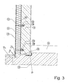
- FIG. 3 shows a sectional view of a section of a building part similar to the building part 10 according to FIG. 1 according to a second embodiment of the invention.
- Like elements have the same reference numerals.
- the base plate 12 is widened around the region 12a, wherein the base plate 12 has a further depression 21 into which a region 23 of the sealing membrane 22 projecting downwards from the finished part 14 protrudes, after which the prefabricated member 14 is correctly positioned on the bottom plate 12 in the recess 28.
- the recess 21 is potted after this positioning of the finished component 14 with a suitable Vergussstoff for sealingly connecting the lower portion 23 of the geomembrane 22 to the bottom plate 12.
- the recess 21 thus serves as Vergussnut and is preferably produced in one operation with the recess 28 during the manufacture of the bottom plate 12.
- a lath is attached to the already mentioned used for producing the recess 28 squared lumber, which serves for shuttering of the above-mentioned Vergussnut.
- Other formwork elements can be used alternatively or in addition to the mentioned squared timber and / or the slat.
- the base plate shown in FIG. 3 is enlarged by the region 12a in order to be able to form the depression 21.
- the recess 21 is attached to the edge of the bottom plate 12, so that the bottom plate 12 spreading area 12a is then not required.
- a temporary or a permanent formwork is used.
- the bottom plate 12 does not necessarily have to be laterally beyond the recess 21 addition.
- a formwork in particular used in the production of the bottom plate 12 edge formwork can be used.
- the embodiment illustrated in FIG. 3 has the advantage that the relatively complex connection of a plurality of joint tapes 13, in particular on outer corners of the base plate 12, can be dispensed with.
- both the vertical region of the adjacent joint tapes and the individual webs of the adjacent joint tapes must be welded together or connected to each other in a relatively complicated manner in a relatively suitable manner.
- the geomembrane 22 and the joint tape 13 must be tightly connected to each other after placing the prefabricated component 14 on the bottom plate 12. This is done, for example, with the aid of the seal web strip 32 mentioned in connection with FIG. 1, which must be connected both to the geomembrane 22 and to the joint tape 13.
- the joint tape can be completely eliminated.
- the recess 21 is disposed in alignment with the sealing sheet 22, wherein the lower portion 23 of the sealing sheet 22 projects into the recess 21 and preferably does not extend to the bottom of the recess 21 so that casting compound flow around the lower portion 23 of the sealing sheet 22 around and can fill the entire recess 21.
- a suitable potting compound such as, for example, epoxy resin or a permanently elastic potting compound.
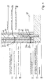
- FIG. 4 shows a sectional view of a section of a building part similar to the sectional views of the sections of building parts according to FIGS. 1 and 3 according to a third embodiment of the invention.
- the wall element is prefabricated as a semi-finished part in a precast plant.
- This semi-finished part comprises a hollow wall 38, which has two spaced concrete shells 50 and 52, each having a reinforcement layer 44, 46 included. Due to the distance between the two concrete shells 50, 52, a gap 51 between these concrete shells 50, 52 is formed.
- the first concrete shell 50 is connected to the second concrete shell 52 via at least one so-called steel lattice girder 48.
- the bottom plate 12 has a connection reinforcement, the reinforcing rods 40, 41 protrude substantially vertically upwards from the bottom plate 12.
- the connecting reinforcement is arranged in such a way that the connecting rods 40, 41 protrude into the intermediate space 51 between the first concrete shell 50 and the second concrete shell 52 when the hollow wall 38 is arranged and aligned on the base plate 12.
- the hollow wall 38 thus also has an at least three-layer structure, wherein the first outer layer is formed by the sealing sheet 22, on the inside of a nonwoven layer 24 is laminated.
- the plastic anchors 25a, 25b are connected in a suitable manner to the inside of the geomembrane or to the fleece 24 laminated to the geomembrane 22 and project inwardly from the inside of the geomembrane 22 or the fleece 24 laminated to the geomembrane, such as already described in detail in connection with the figures 1 to 3.
- a heat-insulating layer 18 formed from local foam is provided on the inside of the geomembrane 22 or of the fleece 24 laminated to the geomembrane 24.
- the second outer concrete shell 52 of the cavity wall 38 is described in each case connected by means of the steel lattice girder 48 or other suitable connection means with the first concrete shell 50, wherein the formed by the first concrete shell 50 outside of the cavity wall 38 preferably forms the inside of a basement to be built.
- the hollow wall 38 is preferably arranged and aligned with a small distance from the bottom plate 12.
- the intermediate space 51 of the cavity wall 38 is cast in the state shown in Figure 4 with in-situ concrete, which then also in the gap formed by the distance between the bottom of the concrete shells 50, 52 and the top of the bottom plate 12 flows and thereby forms a connection between the bottom plate 12 and cavity wall 38.
- this gap can be filled with a suitable material, such as epoxy resin before casting or after the casting of the gap 51 with in-situ concrete by means of suitable methods and / or pressed.
- an insulating strip made of a suitable insulating material can be introduced into this gap or filled with the aid of Ortschaum before casting the gap 51 with in-situ concrete.
- a plastic sealing strip strip 32 is provided as a sealing strip between the plastic sealing strip 22 and the multi-layered joint strip 13, both with the outside of the sealing strip 22 and with the outside of the joint strip 13 after placing and aligning the hollow wall 38 on the bottom plate 12, preferably after the casting of the cavity wall 38 with in-situ concrete, is welded.
- the sealing sheet 22 is inserted into the mold and after positioning the plastic anchors 25a, 25b on the geomembrane 22 or on the nonwoven layer 24 connected to the geomembrane 22, the insulating layer 18 is applied with the aid of local foam. Subsequently, a layer 20 of a suitable adhesive is applied to the insulating layer 18 and applied a concrete layer for forming the second concrete shell 52 on the not yet hardened adhesive of the layer 20, so that the barbs 26a, 26b of the plastic anchor 25a, 25b at least in the concrete layer for producing the second shell 52 protrude.
- a reinforcement layer 44 is introduced, which is preferably formed from one or more reinforcing mats and, if necessary, by further reinforcement allowances.
- the second concrete shell 52 has a thickness of about 7 cm.
- the steel lattice girder 48 is preferably connected to the reinforcement layer 44 of the second concrete shell 52, in particular by means of reinforcing wire, which is wound around both reinforcing bars of the reinforcement layer 44 and around bars of the steel lattice girder 48.
- the steel grid carrier 48 may also be connected to the reinforcement layer 44 by a welded connection.
- a hardening phase for solidifying and curing the concrete used for producing the second concrete shell 52 is provided.
- Such a curing phase lasts for example 8 hours in the present embodiment.
- the second concrete shell 52 connected to the steel lattice girder 48, the thermal barrier layer 18 and the geomembrane 22 is turned and placed in a not yet hardened concrete layer for producing the first concrete shell 50.
- the concrete layer of the first concrete shell 50 has about a thickness of 6 cm. Between the two concrete shells 50, 52 remains a gap 51, for example, 7 cm.
- additional spacers may be provided, which then subsequently in the manufacturing process of the cavity wall 38 to the distance between the side facing the cavity 51 side of the first concrete shell 50 and the gap 51 facing side of the second concrete shell 52 generates and ensures.
- the steel lattice girder 48 may serve as a spacer between the second concrete shell 52 and the first concrete shell 50 even during the production of the cavity wall 38.
- the prefabricated component 14 Even when using the prefabricated component 14 as a basement wall, in which no casting with in-situ concrete on the construction site is required, the prefabricated component 14 must have two layers of reinforcement for structural reasons.
- the two reinforcing layers 44, 46 required for producing the two-shell hollow wall 38 are also required in the case of prefabricated solid walls.
- the prefabricated components 14 designed as solid solid walls can be produced according to FIGS. 1 to 3 with a smaller concrete wall thickness of approximately 14 cm.
- the two-layer reinforcement is preferably inserted as a so-called reinforcement cage.
- the reinforcement layers 44, 46 are each provided in one layer in the respective shell 50, 52, wherein the reinforcement layers 44, 46 are connected to one another via the steel lattice girder 48.
- a hollow wall 38 produced in this way has the advantage that the side of the first concrete shell 50 forming an outer side of the hollow wall 38 is delimited from the underside of a form during the production of the hollow wall 38, whereby a very smooth surface finish of the outside of the first concrete shell 50 can be produced. which meets at least the requirements for a wallpaperable surface.
- the thermal barrier coating 18 may include insulation boards.
- a prefabricated component in the sense of the invention is both a prefabricated component 14 according to FIGS. 1 and 3 and a hollow wall 38 according to FIG. 4.
Landscapes
- Engineering & Computer Science (AREA)
- Architecture (AREA)
- Civil Engineering (AREA)
- Structural Engineering (AREA)
- Building Environments (AREA)
- Filling Or Discharging Of Gas Storage Vessels (AREA)
Applications Claiming Priority (1)
| Application Number | Priority Date | Filing Date | Title |
|---|---|---|---|
| DE200510051316 DE102005051316A1 (de) | 2005-10-26 | 2005-10-26 | Fertigbauteil zum Herstellen eines Bauwerkteils |
Publications (2)
| Publication Number | Publication Date |
|---|---|
| EP1780348A2 true EP1780348A2 (fr) | 2007-05-02 |
| EP1780348A3 EP1780348A3 (fr) | 2008-08-06 |
Family
ID=37696085
Family Applications (1)
| Application Number | Title | Priority Date | Filing Date |
|---|---|---|---|
| EP06120337A Withdrawn EP1780348A3 (fr) | 2005-10-26 | 2006-09-08 | Élément préfabriqué pour fabrication d'un élément de construction |
Country Status (2)
| Country | Link |
|---|---|
| EP (1) | EP1780348A3 (fr) |
| DE (1) | DE102005051316A1 (fr) |
Cited By (8)
| Publication number | Priority date | Publication date | Assignee | Title |
|---|---|---|---|---|
| CN106480999A (zh) * | 2016-12-23 | 2017-03-08 | 万保金 | 预制等厚带叠合梁模壳内隔墙 |
| CN106499090A (zh) * | 2016-12-23 | 2017-03-15 | 万保金 | 预制模壳内置钢管束混凝土墙 |
| CN106499096A (zh) * | 2016-12-23 | 2017-03-15 | 万保金 | 预制模壳内置型钢混凝土墙 |
| CN106499095A (zh) * | 2016-12-23 | 2017-03-15 | 万保金 | 预制模壳内置预应力筋型钢混凝土墙 |
| CN106522411A (zh) * | 2016-12-23 | 2017-03-22 | 万保金 | 预制模壳内置桁架筋混凝土墙 |
| CN106522410A (zh) * | 2016-12-23 | 2017-03-22 | 万保金 | 预制叠合模壳内置型钢混凝土墙 |
| CN106522418A (zh) * | 2016-12-23 | 2017-03-22 | 万保金 | 预制叠合模壳内置预应力型钢混凝土墙 |
| CN117344916A (zh) * | 2023-10-31 | 2024-01-05 | 深圳市百胜建筑科技有限公司 | 一种拼接式预制构件及其施工方法 |
Families Citing this family (2)
| Publication number | Priority date | Publication date | Assignee | Title |
|---|---|---|---|---|
| CN106639055A (zh) * | 2016-12-23 | 2017-05-10 | 万保金 | 预制带叠合梁模壳围护墙 |
| DE102017126966A1 (de) * | 2017-11-16 | 2019-05-16 | Rainer Knecht | Betonfertigteil und Verfahren zur Herstellung eines Betonfertigteils |
Family Cites Families (5)
| Publication number | Priority date | Publication date | Assignee | Title |
|---|---|---|---|---|
| AT285901B (de) * | 1968-10-17 | 1970-11-25 | Semperit Ag | Fertigteilelement |
| DE2355880C2 (de) * | 1973-11-08 | 1982-12-02 | Karl-Ludwig Dr. Fricke | Blecharmiertes plattenförmiges Bauelement |
| DE20301570U1 (de) * | 2003-01-31 | 2003-05-08 | Deutsche Foamglas GmbH, 42781 Haan | Dämmelement für Bauwerke |
| DE202004005037U1 (de) * | 2004-03-31 | 2005-05-19 | Schwörer Haus GmbH & Co. | Kellerwand als Fertigbauteil |
| DE202005005924U1 (de) * | 2005-04-12 | 2005-06-30 | Glatthaar-Fertigkeller Gmbh | Kerngedämmte Fertigteilwand mit Verbundnadeln |
-
2005
- 2005-10-26 DE DE200510051316 patent/DE102005051316A1/de not_active Ceased
-
2006
- 2006-09-08 EP EP06120337A patent/EP1780348A3/fr not_active Withdrawn
Cited By (8)
| Publication number | Priority date | Publication date | Assignee | Title |
|---|---|---|---|---|
| CN106480999A (zh) * | 2016-12-23 | 2017-03-08 | 万保金 | 预制等厚带叠合梁模壳内隔墙 |
| CN106499090A (zh) * | 2016-12-23 | 2017-03-15 | 万保金 | 预制模壳内置钢管束混凝土墙 |
| CN106499096A (zh) * | 2016-12-23 | 2017-03-15 | 万保金 | 预制模壳内置型钢混凝土墙 |
| CN106499095A (zh) * | 2016-12-23 | 2017-03-15 | 万保金 | 预制模壳内置预应力筋型钢混凝土墙 |
| CN106522411A (zh) * | 2016-12-23 | 2017-03-22 | 万保金 | 预制模壳内置桁架筋混凝土墙 |
| CN106522410A (zh) * | 2016-12-23 | 2017-03-22 | 万保金 | 预制叠合模壳内置型钢混凝土墙 |
| CN106522418A (zh) * | 2016-12-23 | 2017-03-22 | 万保金 | 预制叠合模壳内置预应力型钢混凝土墙 |
| CN117344916A (zh) * | 2023-10-31 | 2024-01-05 | 深圳市百胜建筑科技有限公司 | 一种拼接式预制构件及其施工方法 |
Also Published As
| Publication number | Publication date |
|---|---|
| DE102005051316A1 (de) | 2007-05-03 |
| EP1780348A3 (fr) | 2008-08-06 |
Similar Documents
| Publication | Publication Date | Title |
|---|---|---|
| EP1623078B1 (fr) | Procédé pour assembler des parpaings et r aliser une construction de parpaings, construction de parpaings | |
| WO2009007103A2 (fr) | Elément de paroi composite transportable préfabriqué composé de parpaings de coffrage | |
| EP1780348A2 (fr) | Élément préfabriqué pour fabrication d'un élément de construction | |
| EP2169132A2 (fr) | Élément de construction en forme de panneau | |
| DE102005026797A1 (de) | Dämmstoff-Verbundwand | |
| EP1793056A1 (fr) | Elément de cachetage pour la fabrication de parois externes imperméables à l'eau en utilisant des doubles éléments murés en béton | |
| EP2198095B1 (fr) | Procédé permettant de produire une partie de bâtiment au moyen d'un élément de coffrage, et partie de bâtiment construite selon le procédé de l'invention | |
| EP3498929A1 (fr) | Module de bâtiment de construction en hauteur et bâtiment conçu à l'aide dudit module | |
| DE3326856A1 (de) | Bauelement zur herstellung von gebaeudewaenden aus beton, insbesondere zur herstellung von kellerwaenden | |
| EP1630300A1 (fr) | Fondation d' un batiment protecté d' eau | |
| DE102021111093A1 (de) | Fertigteil zur Abdichtung von erdberührten Wänden | |
| DE102017005417B4 (de) | Hausbauschablone sowie hierfür geeignetes Fassadenmodul | |
| DE69700571T2 (de) | Verfahren zur Herstellung eines Paneels mit tragender Holzkonstruktion, durch das Verfahren hergestelltes Paneel, und mindestens ein derartiges Paneel enthaltendes Bauwerk | |
| DE19962088A1 (de) | Wandkonstruktion, Wandbauteil, Wand zur Errichtung von Bauwerken und Verfahren zur Herstellung derselben | |
| DE3021537A1 (de) | Isolierung fuer den hoch- und tiefbau | |
| DE10005351A1 (de) | Fundamentabdichtung durch Kautschukplane | |
| DE102019003036B4 (de) | Wärmedämmbaugruppe | |
| DE1534738A1 (de) | Isolier-Platte | |
| WO2022258682A1 (fr) | Plaque de base pour structures, procédé de fabrication de plaque de base, utilisation d'une plaque de base | |
| EP1632613B1 (fr) | Cave pour des bâtiments | |
| DE2713134C2 (de) | Feuchtigkeitsgeschützte Wärmedämmplatte zur AuBendämmung von Wänden im Erdreich | |
| DE202023101953U1 (de) | Abdichtungsfolie und Baukörper mit Abdichtungsfolie | |
| DE19960512A1 (de) | Verlegevorrichtung und Verfahren zum Erstellen eines Plansteinmauerwerks | |
| EP2011616B1 (fr) | Corps d'isolation pour un mur en béton isolé thermiquement et mur en béton isolé thermiquement tout comme procédé de fabrication | |
| EP1582634A1 (fr) | Elément préfabriqué pour cave et méthode de fabrication |
Legal Events
| Date | Code | Title | Description |
|---|---|---|---|
| PUAI | Public reference made under article 153(3) epc to a published international application that has entered the european phase |
Free format text: ORIGINAL CODE: 0009012 |
|
| AK | Designated contracting states |
Kind code of ref document: A2 Designated state(s): AT BE BG CH CY CZ DE DK EE ES FI FR GB GR HU IE IS IT LI LT LU LV MC NL PL PT RO SE SI SK TR |
|
| AX | Request for extension of the european patent |
Extension state: AL BA HR MK YU |
|
| PUAL | Search report despatched |
Free format text: ORIGINAL CODE: 0009013 |
|
| AK | Designated contracting states |
Kind code of ref document: A3 Designated state(s): AT BE BG CH CY CZ DE DK EE ES FI FR GB GR HU IE IS IT LI LT LU LV MC NL PL PT RO SE SI SK TR |
|
| AX | Request for extension of the european patent |
Extension state: AL BA HR MK RS |
|
| AKX | Designation fees paid | ||
| STAA | Information on the status of an ep patent application or granted ep patent |
Free format text: STATUS: THE APPLICATION IS DEEMED TO BE WITHDRAWN |
|
| 18D | Application deemed to be withdrawn |
Effective date: 20090207 |
|
| REG | Reference to a national code |
Ref country code: DE Ref legal event code: 8566 |