EP1780410B1 - Machine hydraulique à déplacement variable avec plateau en biais - Google Patents
Machine hydraulique à déplacement variable avec plateau en biais Download PDFInfo
- Publication number
- EP1780410B1 EP1780410B1 EP05292265A EP05292265A EP1780410B1 EP 1780410 B1 EP1780410 B1 EP 1780410B1 EP 05292265 A EP05292265 A EP 05292265A EP 05292265 A EP05292265 A EP 05292265A EP 1780410 B1 EP1780410 B1 EP 1780410B1
- Authority
- EP
- European Patent Office
- Prior art keywords
- swash plate
- pistons
- hydraulic machine
- thrust
- piston
- Prior art date
- Legal status (The legal status is an assumption and is not a legal conclusion. Google has not performed a legal analysis and makes no representation as to the accuracy of the status listed.)
- Expired - Lifetime
Links
Images




Classifications
-
- F—MECHANICAL ENGINEERING; LIGHTING; HEATING; WEAPONS; BLASTING
- F04—POSITIVE - DISPLACEMENT MACHINES FOR LIQUIDS; PUMPS FOR LIQUIDS OR ELASTIC FLUIDS
- F04B—POSITIVE-DISPLACEMENT MACHINES FOR LIQUIDS; PUMPS
- F04B1/00—Multi-cylinder machines or pumps characterised by number or arrangement of cylinders
- F04B1/12—Multi-cylinder machines or pumps characterised by number or arrangement of cylinders having cylinder axes coaxial with, or parallel or inclined to, main shaft axis
- F04B1/20—Multi-cylinder machines or pumps characterised by number or arrangement of cylinders having cylinder axes coaxial with, or parallel or inclined to, main shaft axis having rotary cylinder block
- F04B1/2014—Details or component parts
- F04B1/2078—Swash plates
- F04B1/2085—Bearings for swash plates or driving axles
Definitions
- the present invention relates to a hydraulic machine.
- the present invention relates to an axial piston hydraulic machine having variable displacement.
- the second arrangement utilises partial roller bearings with a synchronizing mechanism for angular synchronization of the position of the retaining cage of the bearings relative to the swash plate.
- the partial rolling bearings are more expensive due to the arrangement of the retaining system and synchronizing mechanism.
- US 5 390 584 discloses a follow up mechanism for a swash plate bearing. The swash plate is mounted on rollers in a bearing cage permitting the swash plate to tilt. In addition, angular movement of the first and second ends of a link moves the bearing cage to maintain the proper timing of the bearing cages.
- a further disadvantage of both above-mentioned arrangements is that vibrations are transmitted through the housing towards the surroundings as a redundant noise.
- a further known arrangement for radial bearing of a swash plate comprises a plurality of partial radial sliding bearings. These bearings are used either with partial hydrostatic balance or without hydrostatic balance.
- the disadvantage of both arrangements concerns friction.in the bearing in some operating modes of the axial piston machine. This can be unsuitable with respect to safety in applications of hydrostatic drives for mobile machines.
- US 4 710 107 relates to swashblock lubrication in axial piston fluid displacement devices.
- the rear of the swashblock 26 has a pair of arcuate bearing surfaces, which are supported by the device.
- the friction can also have a negative effect on the control characteristics of the piston machine. Especially if it is a pump for hydrostatic drive of mobile machines, because the quality of some control properties of the hydrostatic drive may decrease.
- the sliding support of a swash plate has better dampening properties.
- pulsating loading from pistons which is transmitted through the swash plate into the housing has the same value as with rolling bearings, so that this loading is responsible for vibrations of the housing and for noise of the axial piston machine.
- EP 1 519 042 discloses a hydraulic machine according to the preamble of claim 1.
- the present invention provides a hydraulic machine according to claim 1.
- the communication between a recess for a thrust piston of the second group and one of the first and second main ducts of the hydraulic machine can be through the piston cylinder.
- a further preferable feature is that the pivotal mounting of the swash plate in the housing comprises two swinging bearings coaxial with said kinematic axis.
- the recesses of the thrust pistons of said first group are hydraulically connected to each other and, preferably, they are permanently hydraulically connected to one of a first and a second main ducts of the machine, which is at the higher pressure.
- a first cylindrical recess for a thrust piston of the second group of thrust pistons is located on a first or right side of the machine defined by a plane perpendicular to the kinematic axis and passing through the rotation axis, and said first cylindrical recess is adapted to be hydraulically connected to a first main duct of the machine, and a second cylindrical recess for a thrust piston of the second group and located on the other (second or left) side of the machine defined by said plane is adapted to be hydraulically connected to a second main duct of the machine.
- said first cylindrical recess of the second group is hydraulically connected to said first main duct via a first pressure channel in the swash plate, which is in communication with a piston cylinder when said piston cylinder is in communication with said first main duct
- said second cylindrical recess of the second group is hydraulically connected to said second main duct via a second pressure channel in the swash plate, which is in communication with a piston cylinder when said piston cylinder is in communication with said second main duct.
- the housing has first and second arcuate bearing surfaces formed thereon, respectively cooperating with the right and left thrust pistons located in cylindrical recesses of first and second corresponding arcuate surfaces of the swash plate.
- a pre-stressed spring is mounted between the thrust piston and the swash plate.
- a pre-stressed spring is located in each of said cylindrical recesses.
- the hydraulic machine comprises at least a right thrust piston of each of the first and second groups located on one side of a plane which is perpendicular to the kinematic axis and passes through the rotation axis of the cylinder block, and at least a left thrust piston of each of the first and second groups located on the other side of said plane.
- the thrust pistons are preferably abutted against first and second arcuate bearing surfaces by a partly cylindrical bearing surface formed in each thrust piston.
- Said partly cylindrical surface has the same profile as the cylindrical arcuate bearing surface of the housing.
- first and second arcuate bearing surfaces can be coaxial with said kinematic axis.
- first and second arcuate bearding surfaces can be eccentric with respect to said kinematic axis.
- the arrangement of the axial piston machine according to the invention substantially eliminates the transmission of pulsating forces generated by the pistons of the cylinder block and transmitted through the swash plate into the housing.
- the bearing arrangement for the swash plate of the hydraulic machine of the invention also reduces bending stress on the swash plate because the balancing force is greater than the loading forces on the swash plate, and consequently the deformation of the swash plate is reduced. This is favourable with respect to the dimensioning and the selection of material for the swash plate.
- a further advantage concerns the reduction of some dimensions of the swash plate and consequently the axial built-in space and weight are reduced, since the bearing on which the swash plate is pivotally mounted in the housing can be a partial bearing, considering that the swash plate is also supported with thrust pistons.
- any type of control of the displacement such as manual, hydraulic or electrohydraulic control can be used.
- a manual control which permits the control of the torque, without the need of servo-valves and servo-cylinders, even for higher values of displacement and applications with higher working pressure compared to the machine of the prior art.
- the friction is at a level, which advantageously provides a low hysteresis of the control forces, which define the characteristics of the pump. Moreover it is possible to modify the behaviour of the control forces, so that it provides the safety of zero displacement at start-up, which is an important safety characteristic in applications for mobile hydrostatic transmissions.
- the present invention substantially eliminates noise and vibrations, which exist in prior art devices (typically in the case of swash plate type axial piston machine with an odd number of pistons).
- the swash plate is maintained in a position during transport without requiring a special hold-on device.
- FIG. 1 shows a hydraulic machine in the form of an axial piston pump unit indicated by the reference numeral 10 comprising a housing member 1.
- the housing member 1 encases a cylinder block 3 driven by a shaft 2, and a swash plate 4, so as to form a hydraulic unit 10.
- the shaft 2 which is connectable to an internal combustion engine (not shown) or other such power source, is rotationally mounted on bearings (not labelled) inside the housing member 1.
- the cylinder block 3 advantageously has an odd number of cylinders 31 machined therein.
- Each cylinder 31 is axially parallel to the axis of rotation of the shaft 2.
- Each cylinder 31 houses a piston 32, which is pivotally connected to a piston rod 33a by means of a spherical joint.
- the piston rod 33a is pivotally connected at its other end to a sliding plate 33b.
- the piston rods 33a and sliding plate 33b together form a transmission device 33 that transmits an axial force from the piston 32 to the swash plate 4.
- the transmission device can be for example also slippers, that is, elements that are connected to the pistons via respective spherical joints at one end, and that are linked together at the other end by a sliding member, sliding on the swash plate.
- the sliding plate 33b is adapted to rotate relative to the swash plate 4 by means of a thrust plate.
- the thrust plate is immovably mounted on the swash plate 4.
- the swash plate 4 is mounted in the housing on two swinging bearings 41, positioned one on either side of the shaft 2 More precisely, it is positioned on either side of a plane, perpendicular to the kinematic axis of tilting 41a of the swash plate 4, and comprising the axis of the shaft 2.
- the kinematic axis of tilting 41a is perpendicular to the axis As of the shaft 2, which it intersects.
- the swinging bearings 41 are spherical bearings with their centers located on the kinematic axis of tilting 41a of the swash plate 4.
- the bearing of the swash plate 4 in the housing can be achieved using any other bearing, which permits tilting of the swash plate in 2 dimensions.
- a valve plate 47 as seen in figure 1 is located between the cylinder block 3 and the housing member 1 at the end of the cylinder block 3 which is furthest from the swash plate 4.
- the valve plate 47 has first and second openings formed therein, respectively located on a first (right) and second (left) opposing sides of the machine defined by a plane perpendicular to the kinematic axis 41 a and passing through the rotation axis As.
- Each one of said first and second openings is hydraulically connected with one of the two main input and output pressure ducts A, B of the pump unit 10.
- the input and output pressure ducts A, B are in fluid communication through the openings of the valve plate 47 with the cylinders 31.
- the input and output pressure ducts A, B of the device are also connectable to a hydraulic motor or other such hydraulic device, not shown in the drawings.
- the swash plate 4 is received in the housing by corresponding first and second arcuate bearing surfaces 1a, 1b, formed on an inner curved arcuate surface of the housing, and being respectively located on a first (right) and second (left) opposing sides of the machine as defined above.
- the swash plate has a first and second arcuate surfaces 4a and 4b, which respectively substantially correspond in shape to the first and second bearing surfaces 1a, 1b.
- the first and second arcuate surfaces 4a, 4b of the swash plate 4 are respectively in correspondence with the first and second openings of the valve plate.
- the swash plate 4 includes a first group of cylindrical recesses 42, and a second group of cylindrical recesses 43a, 43b, formed in the arcuate surfaces 4a, 4b.
- the first group of cylindrical recesses 42 comprises 4 recesses, such that there are two recesses 42 on each surface 4a, 4b.
- the second group of cylindrical recesses 43a, 43b comprises one cylindrical recess 43a, 43b located respectively on each arcuate surface 4a, 4b.
- Each cylindrical recess of the first group 42 has a diameter d1.
- the cylindrical recesses 43a, 43b of the second group each have a diameter d2. In the embodiment shown in the drawings, the diameter d2 is larger than d1.
- a thrust piston 44 is positioned in each of the cylindrical recesses 42, 43a, and 43b.
- Each thrust piston 44 has a spherical side surface 44b formed thereon for contacting the surface of the cylindrical recess 42, 43a, 43b.
- a pre-stressed spring 45 is located in each cylindrical recess 42, 43a, 43b between the swash plate 4 and the thrust piston 44.
- Each thrust piston 44 is axially abutted by a cylindrical bearing surface 44a on one of the first and second arcuate bearing surfaces 1a, 1b, which are immovable with respect to the housing 1. As shown in figure 2 , the arcuate bearing surfaces 1a, 1b are formed directly in the housing 1. The cylindrical bearing surfaces of the thrust pistons have a profile that corresponds to the arcuate cylindrical bearing surface 1a, 1b.
- Each thrust piston 44 has a side surface 44b, which is formed having a profile, which forms a portion of a sphere.
- the spherical portion 44b permits the thrust piston 44 to be angularly tilted inside the cylindrical recess 42, 43a, 43b, such that the axis of the thrust piston 44 can be angularly misaligned relative to the axis of the cylindrical recess 42, 43a, 43b, whilst maintaining a hydrodynamic seal.
- the end surface of the thrust piston 44 which is positionable on the relevant arcuate bearing surface 1a, 1b is formed having a partially cylindrical surface 44a, as created by the intersection of a cylinder with the thrust piston 44, whereby the axis of symmetry of the cylinder is perpendicular to and intersects with the axis At of the thrust piston, therefore the shape of the cylindrical surface 44a is adapted to correspond to the shape of the arcuate surface 1a, 1b, so as to provide evenly distributed contact.
- the partially cylindrical surface 44a has a groove 44d formed therein, defining an annular recess.
- a communication passage formed by a substantially circular recess 44e is located in the partially cylindrical surface 44a and enables fluid circulation between the centre of the thrust piston 44 and the groove 44d.
- a first cylindrical recess 43a of the second group of cylindrical recesses 43a, 43b is hydraulically connected to the first main pressure duct A of the axial piston machine 10 by means of a first pressure channel 46a.
- the first pressure channel 46a is formed by a hollow passage in a piston cylinder 31, in the corresponding piston 32, through the piston rods 33a, in the sliding plate and in the thrust plate whereby the passage extends through the swash plate 4, into the base surface of the cylindrical recess 43a.
- the second cylindrical recess 43b is similarly hydraulically connected to the second main pressure duct B by means of a second pressure channel 46b.
- the first and second pressure channels 46a, 46b can be formed in the housing 1, such that each pressure channels 46a, 46b is connected to one of the cylindrical recesses 43a, 43b, through a hole in one of the arcuate bearing surfaces 1a, 1b.
- the pressure channel 46a, 46b passes through the housing 1 and the opposite end of the pressure channels 46a, 46b is connected to a portion of the main pressure ducts A, B.
- the first bearing surface 1a is arcuate, and has an axis of rotation, which is coaxial with the kinematic axis of tilting 41a.
- the second arcuate bearing surface 1b is determined the same way.
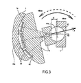
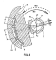
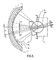
- the arcuate bearing surfaces can be eccentric with respect to the kinematic axis of tilting as seen in a plane, which is perpendicular to the kinematic axis 41a. Further to the advantage of noise reduction due to the influence of the thrust pistons, the eccentricity of the arcuate bearing surfaces in the second embodiment adds the advantage of decreasing requirements on servo-cylinder dimensioning and/or control pressure.
- the eccentricity on that plane can be in the X direction (direction parallel to the axis of the shaft 2) or the Y direction (perpendicular to the axis of the shaft 2).
- a positive X value indicates the centre of the arcuate bearing surface 1a, 1b to be on the side of the kinematic axis 41a closer to the cylinder block 3.
- Each arcuate bearing surface 1a, 1b of the pump unit 10 can have a different centre point, having a given value which is plus or minus in both the X and Y directions.
- the eccentricities in direction X for both arcuate bearing surfaces 1a and 1b have generally the same magnitude and the same direction (+/+ or -/-) and that advantageously the eccentricities in direction Y, perpendicular to the axis of the shaft, also have generally the same magnitude but opposite directions (+/ - or -/+).
- valve devices 5a, 5b can consists of two check valves, or of a well-known shuttle valve or of a selector, which selects the higher pressure.
- the axial piston machine 10 works as a pump, for example in a hydrostatic transmission, and is loaded from a hydraulic motor, considering the first main pressure duct A and the corresponding group of piston cylinders 31 will be at higher pressure than the second main pressure duct B, consequently the first group of cylindrical recesses 42 will be connected through the valve device 5a, 5b to the first main pressure duct A.
- first group of cylindrical recesses 42 and the corresponding second cylindrical recess 43a are connected to the main duct at the higher pressure which is the output working pressure when the hydraulic machine is working as a pump, and the second cylindrical recess 43b is connected to the lower pressure duct B which is at the input pressure when the machine is working as a pump, for example, by a charge valve.
- Each thrust pistons 44 as a result of the hydraulic pressure in the cylindrical recesses 42, 43a, 43b, generates a force, which acts on the swash plate 4, in a direction opposite to the forces generated by the pistons 32.
- the forces acting on both swinging bearings 41 will have the same value and their directions will be from the swash plate 4 towards the cylinder block 3.
- the forces applied to both swinging bearings 41 are subsequently transmitted to the housing 1.
- the forces have a pulsating behavior and the same amplitudes of their variable components.
- the transmission of the pulsating forces occurs over a short distance between the ball bearings 41 and the arcuate bearing surfaces 1a, 1b, which is a characteristic of a great stiffness. This arrangement tends to eliminate vibrations and noise.
- the loading of the swash plate 4 is lower and consequently it is possible to reduce the characteristic dimensions related to this loading and/or to reduce the deformations from the loading of the pistons 32.
- the resultant moment M F will be proportional to the value ⁇ X.sin ⁇ . Since the same working characteristics of the machine are usually required for inclination angle ⁇ , it is important that the X-eccentricity of arcuate bearing surfaces 1a and 1b have the same sign and the same value.
- the resulting moment Mr which is the sum of Msw and MF, will tend to tilt the swash plate 4 towards the zero angular position with a higher moment if eccentricity is -X, regardless of the direction of the shaft rotation because Msw and MF have the same sign or direction (as shown on Table 1).
- the balancing moments (M Fa on the side of arcuate bearing surface 1a, M Fb on the side of arcuate bearing surface 1b) from the thrust pistons 44 are proportional to the value Y*cos ⁇ , so that in the range of the angular inclination ( ⁇ ) of a typical pump displacement it does not change significantly with the angle ( ⁇ ).
- the arcuate bearing surface 1a has an eccentricity of the type -Y, then the moment M Fa from the corresponding thrust pistons 44 on this side will decrease the resultant moment Mr in pump mode and increase the resultant moment Mr in braking or motor mode.
- the moment M Fb from the thrust pistons 44 of this other side will increase the resultant moment Mr in pump mode and decrease it in braking or motor mode.
- the eccentricity Y In order to determine the influence of the eccentricity Y it is necessary to consider together the direction of tilting of the swash plate 4, the direction of rotation of the shaft 2 and the related presence of a pressure load in the appropriate main pressure duct A, B.
- the effect of the eccentricity Y can be optimized by selection of their sign.
- the eccentricities of the right and left arcuate bearing surfaces 1a, 1b preferably have opposite signs to optimally compensate the moment Msw, which has opposite signs in pump and braking or motor modes. It is also due to the fact that the pressure in the second group of cylindrical recesses 43a, 43b is different because of their connection to the different pressure in the first pressure duct A and the second pressure duct B.
- Both types of eccentricity can be combined for optimisation according to the application requirements.
- the force and the moment influences of both types of eccentricity will be super-positioned, because the moments are linear functions of forces.
- With an appropriate arrangement of the mounting of the swash plate 4 of the axial piston machine 10 with an appropriate choice of eccentricities X and Y it is possible to significantly decrease the moments necessary for the control of the angular inclination ( ⁇ ) of the swash plate 4.
- Table 1 Pump working mode in one direction of shaft rotation Direction of swash plate inclination High pressure main conduct Eccentricity of arcuate bearing surface 1a Eccentricity of arcuate bearing surface 1b Direction of M SW Direction of M F Expression of M F (Absolute value) + ⁇ A -X -X CW CW F*X*sin ⁇ -Y +Y CW CCW (F a -F b )*Y*cos ⁇ - ⁇ B -X -X CCW CCW F*X*sin ⁇ -Y +Y CCW CW (F b -F a )*Y*cos ⁇ Table 2: Motor or brake working mode in the same direction of shaft rotation Direction of swash plate inclination High pressure main conduct Eccentricity of arcuate bearing surface 1a Eccentricity of arcuate bearing surface 1b Direction of M SW Direction of M F Expression of M F (Absolute value) + ⁇ B -X -X CCW CW F*X*sin ⁇ -Y +Y CCW CW
- the small values of the axial movement of the thrust pistons 44 towards the swash plate 4 are advantageous for the dimensioning of the swash plate 4, for built-in dimensions of the spring 45, for the guiding of the thrust piston 44 and for the sealing, which can be standard mass produced sealing 44c.
- the arrangement of the axial piston machine 10 according to this invention can have applications on swash plate 4 type axial piston pumps with a variable displacement, in hydrostatic transmissions for mobile machinery and also for stationary applications.
- control of the displacement of the machine such as manual, hydraulic or electro-hydraulic control can be used.
- a direct manual control allowing the control of the torque without the need of servo-valve and servo-cylinders. This becomes possible for higher values of the maximum displacement of the pump and for applications with higher working pressure compared to the prior art.
- notches are defined in the feeding and suction orifices in order to obtain a transition of pressure when a cylinder 31 is commutating and the choice of the shape of these notches corresponds to a compromise between the noise level and the pressure in the cylinders 31.
- the tilting torque due to the pressure in the cylinders 31 acting on the swash plate 4 can be compensated by an optimized eccentricity of the right and left arcuate bearing surfaces 1a, 1b and consequently noise can be more easily reduced so that the design of the valve plate 47 is easier.
Landscapes
- Engineering & Computer Science (AREA)
- Mechanical Engineering (AREA)
- General Engineering & Computer Science (AREA)
- Reciprocating Pumps (AREA)
Claims (18)
- Machine hydraulique (10) comprenant :un carter (1) ;un bloc-cylindres (3) positionné dans le carter (1) et ayant des pistons (32) mobiles par coulissement dans les cylindres (31) ;un arbre (2) raccordé en rotation au bloc-cylindres (3) ;un plateau-came (4) en coopération de charge avec les pistons (32) du bloc-cylindres (3), le plateau-came(4) étant monté de manière pivotante dans le carter (1) au moyen d'au moins un palier, de sorte que ledit plateau-came(4) peut être ajusté de manière pivotante autour d'un axe cinématique (41a) pour modifier un déplacement hydraulique des pistons (32) dans le bloc-cylindres ; etdes pistons de poussée (44) positionnés entre le plateau-came (4) et le carter (1) afin de pousser le plateau-came (4) vers le bloc-cylindres (3),caractérisée en ce que ladite machine (10) comprend des premier et second groupes de pistons de poussée (44) positionnés dans des évidements cylindriques (42, 43a, 43b) dans le plateau-came (4), en ce que ledit carter (1) a des première et seconde surfaces de palier en arc (1a, 1b) respectivement formées sur les premier et second côtés d'un plan perpendiculaire à l'axe cinématique (41a) et passant par l'axe de rotation (As), en ce que ledit premier groupe comprend des pistons qui sont positionnés dans les évidements cylindriques (42) qui sont raccordés hydrauliquement entre eux et qui sont de chaque côté dudit plan, lesdits pistons du premier groupe comprenant des pistons respectifs qui coopèrent avec lesdites première et seconde surfaces de palier (1a, 1b), et en ce que ledit second groupe comprend un premier piston de poussée qui est positionné dans un premier évidement cylindrique (43a), positionné d'un côté dudit plan et adapté pour être raccordé à un premier conduit principal (A) de la machine et un second piston de poussée qui est positionné dans un second évidement cylindrique (43b), positionné de l'autre côté dudit plan et adapté pour être raccordé à un second conduit principal (B) de la machine, lesdits premier et second pistons du second groupe mettant en prise respectivement lesdites première et seconde surfaces en arc.
- Machine hydraulique (10) selon la revendication 1, caractérisée en ce que le montage pivotant du plateau-came (4) dans le carter (1) comprend deux paliers oscillants (41) coaxiaux audit axe cinématique (41a).
- Machine hydraulique (10) selon la revendication 1 ou 2, caractérisée en ce que ledit premier évidement cylindrique (43a) est raccordé audit premier conduit principal (A) via un premier cylindre de piston lorsque ledit premier cylindre de piston (31) est en communication avec ledit premier conduit principal (A), et en ce que ledit second évidement cylindrique (43b) est raccordé au second conduit principal (B) via un second cylindre de piston lorsque ledit second cylindre de piston (31) est en communication avec ledit second conduit principal (B).
- Machine hydraulique (10) selon l'une quelconque des revendications 1 à 3, caractérisée en ce que les évidements cylindriques (42) pour le premier groupe de pistons de poussée (44) sont hydrauliquement raccordés par un dispositif de valve (5) à celui des deux conduits principaux (A, B) de la machine (10), qui est à une pression plus élevée.
- Machine hydraulique (10) selon l'une quelconque des revendications 1 à 4, caractérisée en ce que ledit premier groupe de pistons de poussée (44) comprend quatre pistons de poussée (44), chacun ayant un premier diamètre.
- Machine hydraulique (10) selon l'une quelconque des revendications 1 à 5, caractérisée en ce que le second groupe de pistons de poussée (44) comprend deux pistons de poussée (44) ayant un second diamètre, ledit second diamètre étant plus grand que ledit premier diamètre.
- Machine hydraulique (10) selon l'une quelconque des revendications 1 à 6, caractérisée en ce que les centres desdites première et seconde surfaces de palier en arc (1a, 1b) sont coaxiaux par rapport audit axe cinématique (41a).
- Machine hydraulique (10) selon l'une quelconque des revendications 1 à 7, caractérisée en ce que les première et seconde surfaces de palier en arc (1a, 1b) sont excentriques par rapport audit axe cinématique (41a).
- Machine hydraulique (10) selon la revendication 8, caractérisée en ce que le centre de ladite première surface en arc (1a) est positionné sur un premier côté du plan perpendiculaire à l'axe cinématique (41a) et passant par l'axe de rotation (As), et le centre de ladite seconde surface arquée (1b) est positionné sur le côté opposé dudit plan.
- Machine hydraulique (10) selon la revendication 8, caractérisée en ce que les centres desdites première et seconde surfaces en arc (1a, 1b) sont tous deux positionnés sur un premier côté d'un plan qui est perpendiculaire à l'axe d'arbre et passe par l'axe cinématique (41a).
- Machine hydraulique (10) selon l'une quelconque des revendications 8 à 10, caractérisée en ce que le centre de ladite première surface en arc (1a) est positionné sur un premier côté d'un plan défini par l'axe d'arbre et l'axe cinématique (41a) et le centre de ladite seconde surface en arc (1b) est situé sur un côté opposé du même plan.
- Machine hydraulique (10) selon l'une quelconque des revendications précédentes, caractérisée en ce que ledit au moins un palier comprend un palier sphérique (41).
- Machine hydraulique (10) selon l'une quelconque des revendications précédentes, caractérisée en ce qu'un ressort précontraint (45) est monté dans l'évidement cylindrique (42, 43a, 43b) entre le piston de poussée (44) et le plateau-came(4).
- Machine hydraulique (10) selon l'une quelconque des revendications précédentes, caractérisée en ce que ledit piston de poussée (44) comprend une surface latérale sphérique (44b) en contact avec un évidement cylindrique (42, 43a, 43b) dans lequel le piston de poussée (44) est installé.
- Machine hydraulique (10) selon la revendication 14, caractérisée en ce que ledit piston de poussée (44) est prévu avec une bague d'étanchéité (44c) dans ladite surface latérale (44b).
- Machine hydraulique (10) selon l'une quelconque des revendications 1 à 15, caractérisée en ce que lesdits pistons de poussée (44) s'appuient contre les première et seconde surfaces en arc (1a, 1b) grâce à une surface de palier partiellement cylindrique (44a) formée dans chaque piston de poussée (44).
- Machine hydraulique (10) selon l'une quelconque des revendications précédentes, caractérisée en ce que ladite machine (10) est une pompe.
- Machine hydraulique (10) selon l'une quelconque des revendications précédentes, caractérisée en ce que la communication de fluide entre le piston de poussée (44) et un cylindre de piston est autorisée par un canal de pression (46a) formé à l'intérieur du plateau-came (4) et une ouverture formée dans le cylindre (31) et une conduite formée dans la tige de piston (33) positionnée entre le cylindre (31) et le plateau-came.
Priority Applications (2)
| Application Number | Priority Date | Filing Date | Title |
|---|---|---|---|
| EP05292265A EP1780410B1 (fr) | 2005-10-26 | 2005-10-26 | Machine hydraulique à déplacement variable avec plateau en biais |
| US11/269,971 US7591215B2 (en) | 2005-10-26 | 2005-11-09 | Variable displacement hydraulic machine having a swash plate |
Applications Claiming Priority (1)
| Application Number | Priority Date | Filing Date | Title |
|---|---|---|---|
| EP05292265A EP1780410B1 (fr) | 2005-10-26 | 2005-10-26 | Machine hydraulique à déplacement variable avec plateau en biais |
Publications (2)
| Publication Number | Publication Date |
|---|---|
| EP1780410A1 EP1780410A1 (fr) | 2007-05-02 |
| EP1780410B1 true EP1780410B1 (fr) | 2013-04-03 |
Family
ID=35589389
Family Applications (1)
| Application Number | Title | Priority Date | Filing Date |
|---|---|---|---|
| EP05292265A Expired - Lifetime EP1780410B1 (fr) | 2005-10-26 | 2005-10-26 | Machine hydraulique à déplacement variable avec plateau en biais |
Country Status (2)
| Country | Link |
|---|---|
| US (1) | US7591215B2 (fr) |
| EP (1) | EP1780410B1 (fr) |
Families Citing this family (4)
| Publication number | Priority date | Publication date | Assignee | Title |
|---|---|---|---|---|
| DE102008013010A1 (de) * | 2007-12-28 | 2009-07-02 | Robert Bosch Gmbh | Schwenkwiegenlagerung für Axialkolbenmaschinen |
| WO2014187512A1 (fr) * | 2013-05-22 | 2014-11-27 | Hydac Drive Center Gmbh | Pompe à pistons axiaux de type à plateau inclinable |
| CN110067718A (zh) * | 2018-05-22 | 2019-07-30 | 钟彪 | 一种球面静压支承滑盘副结构及包含该结构的斜盘式柱塞泵或马达 |
| DE102020216394A1 (de) * | 2020-12-21 | 2022-06-23 | Danfoss Power Solutions Gmbh & Co. Ohg | Wiegenlager und Abstützung eines Wiegenlagers |
Family Cites Families (10)
| Publication number | Priority date | Publication date | Assignee | Title |
|---|---|---|---|---|
| US2737895A (en) * | 1952-11-19 | 1956-03-13 | Oilgear Co | Axial type pump |
| US2871798A (en) * | 1955-12-07 | 1959-02-03 | Thoma Hans Johannes | Hydraulic power transmissions |
| US3862588A (en) * | 1969-07-31 | 1975-01-28 | Firm Of Constantin Rauch | Method of operating an axial piston machine having a hydrostatic bearing load relief device |
| JPS59113274A (ja) * | 1982-12-20 | 1984-06-29 | Kayaba Ind Co Ltd | 可変型油圧アクチユエ−タ |
| US4710107A (en) | 1986-04-15 | 1987-12-01 | The Oilgear Company | Swashblock lubrication in axial piston fluid displacement devices |
| DE3743125A1 (de) * | 1987-12-18 | 1989-07-06 | Brueninghaus Hydraulik Gmbh | Axialkolbenpumpe |
| GB2274491B (en) * | 1993-01-21 | 1996-09-04 | Hamworthy Hydraulics Ltd | Axial piston pump |
| JPH0783161A (ja) | 1993-09-17 | 1995-03-28 | Kanzaki Kokyukoki Mfg Co Ltd | 可変容量型アキシャルピストン機械 |
| US5390584A (en) | 1993-10-25 | 1995-02-21 | Caterpillar Inc. | Follow up mechanism for a swashplate bearing |
| EP1519042B1 (fr) * | 2003-09-29 | 2006-08-16 | Kayaba Industry Co., Ltd. | Pompe ou moteur avec plateau en biais |
-
2005
- 2005-10-26 EP EP05292265A patent/EP1780410B1/fr not_active Expired - Lifetime
- 2005-11-09 US US11/269,971 patent/US7591215B2/en not_active Expired - Fee Related
Also Published As
| Publication number | Publication date |
|---|---|
| EP1780410A1 (fr) | 2007-05-02 |
| US7591215B2 (en) | 2009-09-22 |
| US20070089600A1 (en) | 2007-04-26 |
Similar Documents
| Publication | Publication Date | Title |
|---|---|---|
| CA1293671C (fr) | Transmission a variation continue de rapport de demultiplication, avec soupape d'embrayage | |
| US4478134A (en) | Swash plate type hydraulic device | |
| CA2303035C (fr) | Dispositif hydraulique a plateaux inclines | |
| US8727743B2 (en) | Opposing swash plate piston pump/motor | |
| CN110067855B (zh) | 一种液压无级变速传动装置 | |
| US8356547B2 (en) | Variable length bent-axis pump/motor | |
| US5094144A (en) | Bent axis type variable displacement hydraulic machine | |
| EP1519042A1 (fr) | Pompe ou moteur avec plateau en biais | |
| US6206650B1 (en) | Variable axial piston displacement machine with maximized swivel angle | |
| US20110229347A1 (en) | Wabble plate type variable displacement compressor | |
| US3785250A (en) | Piston-type machine | |
| KR20140012685A (ko) | 정유압 모듈의 조절 장치 | |
| US4688439A (en) | Wabble plate engine mechansim | |
| US7591215B2 (en) | Variable displacement hydraulic machine having a swash plate | |
| US5249512A (en) | hydrostatic pump and motor | |
| EP2306013B1 (fr) | Compresseur à déplacement variable de type à plateau oscillant | |
| US3211105A (en) | Hydraulic pump or motor | |
| EP2306015B1 (fr) | Compresseur à déplacement variable du type à plateau oscillant | |
| US10302073B2 (en) | Axial hydraulic piston pump | |
| JP4888123B2 (ja) | 可変容量形ピストンポンプ・モータ | |
| JP5060213B2 (ja) | サーボレギュレータ | |
| JPH0562261B2 (fr) | ||
| US3274950A (en) | Axial piston fluid pumps or motors | |
| CA1299062C (fr) | Transmission a variation continue de la vitesse, a valve tiroir | |
| US20180051682A1 (en) | Wobble Plate Type Variable Displacement Compressor |
Legal Events
| Date | Code | Title | Description |
|---|---|---|---|
| PUAI | Public reference made under article 153(3) epc to a published international application that has entered the european phase |
Free format text: ORIGINAL CODE: 0009012 |
|
| AK | Designated contracting states |
Kind code of ref document: A1 Designated state(s): AT BE BG CH CY CZ DE DK EE ES FI FR GB GR HU IE IS IT LI LT LU LV MC NL PL PT RO SE SI SK TR |
|
| AX | Request for extension of the european patent |
Extension state: AL BA HR MK YU |
|
| 17P | Request for examination filed |
Effective date: 20071025 |
|
| AKX | Designation fees paid |
Designated state(s): AT BE BG CH CY CZ DE DK EE ES FI FR GB GR HU IE IS IT LI LT LU LV MC NL PL PT RO SE SI SK TR |
|
| 17Q | First examination report despatched |
Effective date: 20080117 |
|
| GRAP | Despatch of communication of intention to grant a patent |
Free format text: ORIGINAL CODE: EPIDOSNIGR1 |
|
| GRAS | Grant fee paid |
Free format text: ORIGINAL CODE: EPIDOSNIGR3 |
|
| GRAP | Despatch of communication of intention to grant a patent |
Free format text: ORIGINAL CODE: EPIDOSNIGR1 |
|
| GRAA | (expected) grant |
Free format text: ORIGINAL CODE: 0009210 |
|
| AK | Designated contracting states |
Kind code of ref document: B1 Designated state(s): AT BE BG CH CY CZ DE DK EE ES FI FR GB GR HU IE IS IT LI LT LU LV MC NL PL PT RO SE SI SK TR |
|
| REG | Reference to a national code |
Ref country code: GB Ref legal event code: FG4D |
|
| REG | Reference to a national code |
Ref country code: CH Ref legal event code: EP Ref country code: AT Ref legal event code: REF Ref document number: 604903 Country of ref document: AT Kind code of ref document: T Effective date: 20130415 |
|
| REG | Reference to a national code |
Ref country code: IE Ref legal event code: FG4D |
|
| REG | Reference to a national code |
Ref country code: DE Ref legal event code: R096 Ref document number: 602005038868 Country of ref document: DE Effective date: 20130529 |
|
| REG | Reference to a national code |
Ref country code: SE Ref legal event code: TRGR |
|
| REG | Reference to a national code |
Ref country code: SK Ref legal event code: T3 Ref document number: E 14105 Country of ref document: SK |
|
| REG | Reference to a national code |
Ref country code: AT Ref legal event code: MK05 Ref document number: 604903 Country of ref document: AT Kind code of ref document: T Effective date: 20130403 |
|
| PG25 | Lapsed in a contracting state [announced via postgrant information from national office to epo] |
Ref country code: SI Free format text: LAPSE BECAUSE OF FAILURE TO SUBMIT A TRANSLATION OF THE DESCRIPTION OR TO PAY THE FEE WITHIN THE PRESCRIBED TIME-LIMIT Effective date: 20130403 |
|
| REG | Reference to a national code |
Ref country code: NL Ref legal event code: VDEP Effective date: 20130403 |
|
| REG | Reference to a national code |
Ref country code: LT Ref legal event code: MG4D |
|
| PG25 | Lapsed in a contracting state [announced via postgrant information from national office to epo] |
Ref country code: LT Free format text: LAPSE BECAUSE OF FAILURE TO SUBMIT A TRANSLATION OF THE DESCRIPTION OR TO PAY THE FEE WITHIN THE PRESCRIBED TIME-LIMIT Effective date: 20130403 Ref country code: GR Free format text: LAPSE BECAUSE OF FAILURE TO SUBMIT A TRANSLATION OF THE DESCRIPTION OR TO PAY THE FEE WITHIN THE PRESCRIBED TIME-LIMIT Effective date: 20130704 Ref country code: ES Free format text: LAPSE BECAUSE OF FAILURE TO SUBMIT A TRANSLATION OF THE DESCRIPTION OR TO PAY THE FEE WITHIN THE PRESCRIBED TIME-LIMIT Effective date: 20130714 Ref country code: NL Free format text: LAPSE BECAUSE OF FAILURE TO SUBMIT A TRANSLATION OF THE DESCRIPTION OR TO PAY THE FEE WITHIN THE PRESCRIBED TIME-LIMIT Effective date: 20130403 Ref country code: PT Free format text: LAPSE BECAUSE OF FAILURE TO SUBMIT A TRANSLATION OF THE DESCRIPTION OR TO PAY THE FEE WITHIN THE PRESCRIBED TIME-LIMIT Effective date: 20130805 Ref country code: AT Free format text: LAPSE BECAUSE OF FAILURE TO SUBMIT A TRANSLATION OF THE DESCRIPTION OR TO PAY THE FEE WITHIN THE PRESCRIBED TIME-LIMIT Effective date: 20130403 Ref country code: FI Free format text: LAPSE BECAUSE OF FAILURE TO SUBMIT A TRANSLATION OF THE DESCRIPTION OR TO PAY THE FEE WITHIN THE PRESCRIBED TIME-LIMIT Effective date: 20130403 Ref country code: IS Free format text: LAPSE BECAUSE OF FAILURE TO SUBMIT A TRANSLATION OF THE DESCRIPTION OR TO PAY THE FEE WITHIN THE PRESCRIBED TIME-LIMIT Effective date: 20130803 Ref country code: BE Free format text: LAPSE BECAUSE OF FAILURE TO SUBMIT A TRANSLATION OF THE DESCRIPTION OR TO PAY THE FEE WITHIN THE PRESCRIBED TIME-LIMIT Effective date: 20130403 |
|
| PG25 | Lapsed in a contracting state [announced via postgrant information from national office to epo] |
Ref country code: PL Free format text: LAPSE BECAUSE OF FAILURE TO SUBMIT A TRANSLATION OF THE DESCRIPTION OR TO PAY THE FEE WITHIN THE PRESCRIBED TIME-LIMIT Effective date: 20130403 Ref country code: CY Free format text: LAPSE BECAUSE OF FAILURE TO SUBMIT A TRANSLATION OF THE DESCRIPTION OR TO PAY THE FEE WITHIN THE PRESCRIBED TIME-LIMIT Effective date: 20130403 Ref country code: BG Free format text: LAPSE BECAUSE OF FAILURE TO SUBMIT A TRANSLATION OF THE DESCRIPTION OR TO PAY THE FEE WITHIN THE PRESCRIBED TIME-LIMIT Effective date: 20130703 Ref country code: LV Free format text: LAPSE BECAUSE OF FAILURE TO SUBMIT A TRANSLATION OF THE DESCRIPTION OR TO PAY THE FEE WITHIN THE PRESCRIBED TIME-LIMIT Effective date: 20130403 |
|
| PG25 | Lapsed in a contracting state [announced via postgrant information from national office to epo] |
Ref country code: CZ Free format text: LAPSE BECAUSE OF FAILURE TO SUBMIT A TRANSLATION OF THE DESCRIPTION OR TO PAY THE FEE WITHIN THE PRESCRIBED TIME-LIMIT Effective date: 20130403 Ref country code: EE Free format text: LAPSE BECAUSE OF FAILURE TO SUBMIT A TRANSLATION OF THE DESCRIPTION OR TO PAY THE FEE WITHIN THE PRESCRIBED TIME-LIMIT Effective date: 20130403 Ref country code: DK Free format text: LAPSE BECAUSE OF FAILURE TO SUBMIT A TRANSLATION OF THE DESCRIPTION OR TO PAY THE FEE WITHIN THE PRESCRIBED TIME-LIMIT Effective date: 20130403 |
|
| PLBE | No opposition filed within time limit |
Free format text: ORIGINAL CODE: 0009261 |
|
| STAA | Information on the status of an ep patent application or granted ep patent |
Free format text: STATUS: NO OPPOSITION FILED WITHIN TIME LIMIT |
|
| PG25 | Lapsed in a contracting state [announced via postgrant information from national office to epo] |
Ref country code: RO Free format text: LAPSE BECAUSE OF FAILURE TO SUBMIT A TRANSLATION OF THE DESCRIPTION OR TO PAY THE FEE WITHIN THE PRESCRIBED TIME-LIMIT Effective date: 20130403 |
|
| 26N | No opposition filed |
Effective date: 20140106 |
|
| REG | Reference to a national code |
Ref country code: DE Ref legal event code: R097 Ref document number: 602005038868 Country of ref document: DE Effective date: 20140106 |
|
| PG25 | Lapsed in a contracting state [announced via postgrant information from national office to epo] |
Ref country code: MC Free format text: LAPSE BECAUSE OF FAILURE TO SUBMIT A TRANSLATION OF THE DESCRIPTION OR TO PAY THE FEE WITHIN THE PRESCRIBED TIME-LIMIT Effective date: 20130403 |
|
| REG | Reference to a national code |
Ref country code: CH Ref legal event code: PL |
|
| REG | Reference to a national code |
Ref country code: IE Ref legal event code: MM4A |
|
| PG25 | Lapsed in a contracting state [announced via postgrant information from national office to epo] |
Ref country code: CH Free format text: LAPSE BECAUSE OF NON-PAYMENT OF DUE FEES Effective date: 20131031 Ref country code: LI Free format text: LAPSE BECAUSE OF NON-PAYMENT OF DUE FEES Effective date: 20131031 |
|
| PG25 | Lapsed in a contracting state [announced via postgrant information from national office to epo] |
Ref country code: IE Free format text: LAPSE BECAUSE OF NON-PAYMENT OF DUE FEES Effective date: 20131026 |
|
| PG25 | Lapsed in a contracting state [announced via postgrant information from national office to epo] |
Ref country code: TR Free format text: LAPSE BECAUSE OF FAILURE TO SUBMIT A TRANSLATION OF THE DESCRIPTION OR TO PAY THE FEE WITHIN THE PRESCRIBED TIME-LIMIT Effective date: 20130403 |
|
| PG25 | Lapsed in a contracting state [announced via postgrant information from national office to epo] |
Ref country code: LU Free format text: LAPSE BECAUSE OF NON-PAYMENT OF DUE FEES Effective date: 20131026 Ref country code: HU Free format text: LAPSE BECAUSE OF FAILURE TO SUBMIT A TRANSLATION OF THE DESCRIPTION OR TO PAY THE FEE WITHIN THE PRESCRIBED TIME-LIMIT; INVALID AB INITIO Effective date: 20051026 |
|
| REG | Reference to a national code |
Ref country code: FR Ref legal event code: PLFP Year of fee payment: 11 |
|
| PGFP | Annual fee paid to national office [announced via postgrant information from national office to epo] |
Ref country code: SK Payment date: 20150922 Year of fee payment: 11 |
|
| PGFP | Annual fee paid to national office [announced via postgrant information from national office to epo] |
Ref country code: DE Payment date: 20151014 Year of fee payment: 11 Ref country code: IT Payment date: 20151014 Year of fee payment: 11 Ref country code: GB Payment date: 20151019 Year of fee payment: 11 |
|
| PGFP | Annual fee paid to national office [announced via postgrant information from national office to epo] |
Ref country code: SE Payment date: 20151014 Year of fee payment: 11 |
|
| REG | Reference to a national code |
Ref country code: FR Ref legal event code: PLFP Year of fee payment: 12 |
|
| REG | Reference to a national code |
Ref country code: DE Ref legal event code: R119 Ref document number: 602005038868 Country of ref document: DE |
|
| GBPC | Gb: european patent ceased through non-payment of renewal fee |
Effective date: 20161026 |
|
| REG | Reference to a national code |
Ref country code: SK Ref legal event code: MM4A Ref document number: E 14105 Country of ref document: SK Effective date: 20161026 |
|
| PG25 | Lapsed in a contracting state [announced via postgrant information from national office to epo] |
Ref country code: GB Free format text: LAPSE BECAUSE OF NON-PAYMENT OF DUE FEES Effective date: 20161026 Ref country code: DE Free format text: LAPSE BECAUSE OF NON-PAYMENT OF DUE FEES Effective date: 20170503 Ref country code: SK Free format text: LAPSE BECAUSE OF NON-PAYMENT OF DUE FEES Effective date: 20161026 |
|
| PG25 | Lapsed in a contracting state [announced via postgrant information from national office to epo] |
Ref country code: SE Free format text: LAPSE BECAUSE OF NON-PAYMENT OF DUE FEES Effective date: 20161027 |
|
| REG | Reference to a national code |
Ref country code: FR Ref legal event code: PLFP Year of fee payment: 13 |
|
| PG25 | Lapsed in a contracting state [announced via postgrant information from national office to epo] |
Ref country code: IT Free format text: LAPSE BECAUSE OF NON-PAYMENT OF DUE FEES Effective date: 20161026 |
|
| REG | Reference to a national code |
Ref country code: FR Ref legal event code: PLFP Year of fee payment: 14 |
|
| P01 | Opt-out of the competence of the unified patent court (upc) registered |
Effective date: 20230513 |
|
| PGFP | Annual fee paid to national office [announced via postgrant information from national office to epo] |
Ref country code: FR Payment date: 20231023 Year of fee payment: 19 |
|
| PG25 | Lapsed in a contracting state [announced via postgrant information from national office to epo] |
Ref country code: FR Free format text: LAPSE BECAUSE OF NON-PAYMENT OF DUE FEES Effective date: 20241031 |