EP1780435A2 - Embrayage double en forme radial - Google Patents
Embrayage double en forme radial Download PDFInfo
- Publication number
- EP1780435A2 EP1780435A2 EP06018430A EP06018430A EP1780435A2 EP 1780435 A2 EP1780435 A2 EP 1780435A2 EP 06018430 A EP06018430 A EP 06018430A EP 06018430 A EP06018430 A EP 06018430A EP 1780435 A2 EP1780435 A2 EP 1780435A2
- Authority
- EP
- European Patent Office
- Prior art keywords
- transmission
- clutch
- transmission input
- input shaft
- radially
- Prior art date
- Legal status (The legal status is an assumption and is not a legal conclusion. Google has not performed a legal analysis and makes no representation as to the accuracy of the status listed.)
- Granted
Links
Images
Classifications
-
- F—MECHANICAL ENGINEERING; LIGHTING; HEATING; WEAPONS; BLASTING
- F16—ENGINEERING ELEMENTS AND UNITS; GENERAL MEASURES FOR PRODUCING AND MAINTAINING EFFECTIVE FUNCTIONING OF MACHINES OR INSTALLATIONS; THERMAL INSULATION IN GENERAL
- F16D—COUPLINGS FOR TRANSMITTING ROTATION; CLUTCHES; BRAKES
- F16D25/00—Fluid-actuated clutches
- F16D25/06—Fluid-actuated clutches in which the fluid actuates a piston incorporated in, i.e. rotating with the clutch
- F16D25/062—Fluid-actuated clutches in which the fluid actuates a piston incorporated in, i.e. rotating with the clutch the clutch having friction surfaces
- F16D25/063—Fluid-actuated clutches in which the fluid actuates a piston incorporated in, i.e. rotating with the clutch the clutch having friction surfaces with clutch members exclusively moving axially
- F16D25/0635—Fluid-actuated clutches in which the fluid actuates a piston incorporated in, i.e. rotating with the clutch the clutch having friction surfaces with clutch members exclusively moving axially with flat friction surfaces, e.g. discs
- F16D25/0638—Fluid-actuated clutches in which the fluid actuates a piston incorporated in, i.e. rotating with the clutch the clutch having friction surfaces with clutch members exclusively moving axially with flat friction surfaces, e.g. discs with more than two discs, e.g. multiple lamellae
-
- F—MECHANICAL ENGINEERING; LIGHTING; HEATING; WEAPONS; BLASTING
- F16—ENGINEERING ELEMENTS AND UNITS; GENERAL MEASURES FOR PRODUCING AND MAINTAINING EFFECTIVE FUNCTIONING OF MACHINES OR INSTALLATIONS; THERMAL INSULATION IN GENERAL
- F16D—COUPLINGS FOR TRANSMITTING ROTATION; CLUTCHES; BRAKES
- F16D25/00—Fluid-actuated clutches
- F16D25/10—Clutch systems with a plurality of fluid-actuated clutches
-
- F—MECHANICAL ENGINEERING; LIGHTING; HEATING; WEAPONS; BLASTING
- F16—ENGINEERING ELEMENTS AND UNITS; GENERAL MEASURES FOR PRODUCING AND MAINTAINING EFFECTIVE FUNCTIONING OF MACHINES OR INSTALLATIONS; THERMAL INSULATION IN GENERAL
- F16D—COUPLINGS FOR TRANSMITTING ROTATION; CLUTCHES; BRAKES
- F16D21/00—Systems comprising a plurality of actuated clutches
- F16D21/02—Systems comprising a plurality of actuated clutches for interconnecting three or more shafts or other transmission members in different ways
- F16D21/06—Systems comprising a plurality of actuated clutches for interconnecting three or more shafts or other transmission members in different ways at least two driving shafts or two driven shafts being concentric
- F16D2021/0661—Hydraulically actuated multiple lamellae clutches
Definitions
- the invention relates to a dual clutch device, for the arrangement in a drive train of a motor vehicle between a drive unit and a transmission, wherein the clutch means comprises a first transmission input shaft of the transmission associated first clutch assembly and a second transmission input shaft of the transmission associated second clutch assembly for torque transmission between the drive unit and the transmission, and wherein at least one of the transmission input shafts is formed as a hollow shaft and one of the transmission input shafts through the other, designed as a hollow shaft transmission input shaft, and wherein the clutch assemblies are formed as radially arranged wet-running disk clutch assemblies.
- the invention particularly relates to such a double clutch device, in which the clutch assemblies are each designed with an integrated, co-rotating in operation hydraulic actuatable actuating piston, via which the respective clutch assembly is hydraulically actuated, and such a coupling device, wherein the clutch assemblies for a Running under the action of an operating medium provided, in particular designed as a wet-running multi-disc clutch assembly, wherein alternately arranged an inner disc carrier associated inner plates and an outer plate carrier associated outer plates for torque transmission are frictionally engageable and a rotatably connected to the outer disk carrier of the radially outer clutch assembly torque transmission member as the input side of Dual clutch device is used and wherein and wherein the clutch assemblies comprise a common oil supply hub, via which the coupling device is mounted or storable by means of a bearing assembly on at least one of the transmission input shafts.
- double clutch devices are from the DE 103 27 729 A1 known, in which the piston chambers and the rotary pressure compensation chambers with special to the piston and sealed to the plate carriers welded separate seal assemblies. This will replace the vulcanized to the components seals, which pulls in a faulty production process of seals the Committee of relatively expensive compared to the seals piston and disk carriers.
- the disadvantage here is the overall costly welding operations, since a total of four seal assemblies must be welded, and the two outer disk carrier of the clutch assemblies and the boundary wall of the rotary pressure compensation chamber of the radially inner coupling must be welded to the oil supply hub.
- the clutch assemblies have a common oil supply hub, via which they are stored or storable by means of a first bearing assembly on the formed as a hollow shaft transmission input shaft and that that a second bearing assembly for mounting the dual clutch device between a torque transmitting member and the inner transmission input shaft is provided.
- the advantage here is that both the ⁇ lzu Siliconnabe and the torque transmission member is assigned to both clutch assemblies together, and that the storage of the coupling device via both transmission input shafts. This allows Forcing forces, which result by axial offset between the drive unit and the transmission, are better compensated.
- the transmission-side first bearing assembly is designed as a radial needle bearing on the outer transmission input shaft and the second bearing assembly as a deep groove ball bearing on the inner transmission input shaft.
- the deep groove ball bearing serves for the axial and radial mounting of the double clutch device. The advantage here is the low axial space requirement of the deep groove ball bearing.
- the coupling device is mounted or storable via an oil supply hub by means of a first bearing arrangement on the transmission input shaft designed as a hollow shaft and that the transmission input shaft extending through the hollow shaft, which is assigned to the radially outer clutch arrangement, by means of a second bearing arrangement directly or indirectly mounted on a crankshaft flange of the drive unit is relatively rotatable or storable.
- a first bearing arrangement on the transmission input shaft designed as a hollow shaft
- the transmission input shaft extending through the hollow shaft which is assigned to the radially outer clutch arrangement
- a second bearing arrangement directly or indirectly mounted on a crankshaft flange of the drive unit is relatively rotatable or storable.
- the second bearing assembly is designed as a needle bearing and arranged directly in the crankshaft.
- a primary side of the torsion damper is firmly bolted to the crankshaft and a pilot bearing between a cylindrical inner peripheral surface of the primary side and the inner transmission input shaft is provided, whereby the inner transmission input shaft is indirectly rotatably mounted or storable on a crankshaft flange of the drive unit.
- the outside diameter of the double clutch device is preferably more than twenty centimeters and the ratio of the diameter of the double clutch device to the axial width is more than two.
- the axial width is less than eight centimeters and the ratio of diameter to axial width at the level of the disk pack of the radially inner clutch assembly is more than a factor of 2.5.
- An advantageous embodiment of the dual clutch device further provides that the number of friction pairings formed by the inner disks and the outer disks of the radially outer clutch assembly is greater than the number of friction pairings formed by the inner disks and the outer disks of the radially inner clutch assembly ,
- the radially outer clutch assembly has twelve friction pairings.
- An essential aspect of the invention provides that in a radially central region of the torque transmission member arranged with a arranged on an inner peripheral portion Veriereungsprofil coupling member for coupling an output side of an upstream torsional vibration damper is arranged.
- the advantage here is that a space thus incurred radially inside half of the coupling member can be used elsewhere, so that axial space can be used twice.
- An advantageous embodiment of the dual clutch device further provides that on a outer peripheral portion of the coupling member a wet space defining wall is sealingly guided and that in at least one axial portion radially within the coupling member, a sealing element and / or a radial bearing assembly between the torque transmitting member and the inner transmission input shaft is arranged ,
- the advantage here is that the axial space in the region of the coupling member thus for coupling an output side of an upstream torsional vibration damper, for the arrangement of the wet room bounding wall and for the arrangement of a sealing element and / or a radial bearing assembly is used.
- the sealing element is provided as a radial shaft sealing ring between the torque transmitting member and the inner transmission input shaft.
- the two clutch assemblies have actuatable disk packs by means of hydraulically actuable pistons, which each have an inner disk carrier rotatably mounted inner disks and with an outer disk carrier rotatably disposed outer disks and wherein for cooling the disk packs, the double clutch device from radially inside in Essentially radially outside with cooling oil is flowed through and wherein the actuating piston is associated with one, connected to a cooling oil supply, Rotations réelleaus somnsraum, wherein an axial region of the radially outer coupling associated piston is pushed radially actuated clutch assembly within an axial region of the inner clutch assembly associated outer disk carrier.
- the advantage here is the reduced axial space requirement for the rotary pressure compensation chamber, which is formed with the piston actuated substantially as an annular gap with the axial width of the rotary pressure compensation chamber radially outwardly sealing sealing element.
- a further advantageous embodiment of the dual clutch device for minimizing the axial space requirement in the radially outer region of the dual clutch device provides that the torque transmission member is welded at its outer periphery to a cylindrical end portion of the outer disk carrier of the radially outer clutch assembly, wherein the outer diameter of the cylindrical end portion greater than the outer diameter of the lamellentragenden toothing region of the outer disk carrier is formed.
- a very short axial region is formed, in which the toothed region terminates.
- An advantageous method for designing such a tooth profile is achieved here by means of punch slides.
- the advantage here is that a voltage applied to the torque transmitting member motor side formed as an outer fin end plate of the disk set with respect to the axial thickness can be identical to the other outer disk.
- the outer plates are designed as steel plates and the corresponding inner plates as lining-carrying inner plates.
- each of the two actuating piston is associated with a sealed piston chamber and a sealed rotation pressure compensation chamber, each radially outward with a separate seal assembly are sealed and wherein at least the seal assemblies of the piston chamber and the Rotations réelleaus somnsraums of the inner clutch assembly are held by friction or spring force in contact with the seal assemblies bearing member and wherein the piston chambers radially inwardly each with a arranged in an annular groove of the ⁇ lzu semiconductornabe sealing element
- the piston chamber of the radially inner clutch assembly radially outwardly sealing sealing arrangement is formed at least from a seal element holder and a sealing element and pushed onto an axial region of the outer disk carrier of the inner clutch assembly.
- the sealing element holder is preferably formed as a support plate, which has a radially outwardly directed portion which is pushed in case of release of the seal assembly from the fixed seat on the outer disk carrier during retraction of the actuating piston back into axial contact with the outer disk carrier. Furthermore, it is provided that the support plate is formed on the inner periphery with an elastic sealing element for sealing a gap between the outer disk carrier and the seal assembly.
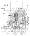
- a dual clutch device 12 which is designed as a double clutch with two radially arranged multi-plate clutches 64, 72.
- the two multi-plate clutches are hydraulically actuated by means of rotating actuating pistons 40, 42, pressure medium, preferably hydraulic oil, being conveyed via the oil feed hub 44 into the two piston chambers 46, 48 via a hydraulic unit, not shown.
- the piston chambers 46, 48 are sealed radially outwardly by means of sealing arrangements 60, 62 and radially inwardly by means of sealing elements 74, 76, which are arranged in annular grooves in the oil supply hub.
- the torque is introduced via the crankshaft flange 100 of a drive unit not shown via a torsional vibration damper 20 in the dual clutch device 12.
- the primary side 102 which consists of axially elastically formed hardened sheets is screwed by means of a screw 104 directly without interposition of a lock washer on the crankshaft flange 100.
- the secondary side 106 of the torsional vibration damper 20 is rotatably coupled to an axial outer toothed region 108 on the coupling element 110, which has a corresponding inner toothed region on the inner circumference.
- the coupling element 110 is fastened to the torque transmission element 14 with a rivet 112.
- the torque transmitting member 14 is welded with its outer periphery in a fold at the cylindrical end of the disk carrier 6.
- a tooth profile is formed, which receives the seven outer disks 22 rotationally fixed.
- the outer disks are formed on their outer circumference with a corresponding external toothing.
- the tooth profile 21 extends radially outward, whereby at the end-side cylinder portion a cylindrical edge region is formed, in which the fold is screwed.
- the torque is transmitted from the drive unit via the torque transmitting member 14 through the welded joint on the plate carrier 6 and the oil supply hub 44 and transmitted from there via the outer disk carrier 7 in the radially inner clutch assembly 72, which via their disk set the torque when operating on the inner disk carrier 51 and the outer, designed as a hollow shaft, transmission input shaft 24 in the Dual-clutch transmission transmits.
- the inner transmission input shaft 22 is supported by the bearing assembly 2 in the crankshaft flange 100.
- the oil supply hub 44 is mounted on the outer transmission input shaft 24 by means of the needle bearing 4.
- the deep groove ball bearing 5 is arranged, which is arranged between an axial securing element 114 and a hub of the inner disk carrier 50.
- a locking washer 136 is welded thereto.
- Motor side next to the locking ring 114 of the radial shaft seal 116 is arranged.
- the deep groove ball bearing 5 may be formed with integrated sealing disc, whereby the separate radial shaft seal 116 may be omitted.
- a round wire ring 118 inserted in the transmission input shaft 24 is provided, which serves as an axial stop of the hub 120 of the inner disk carrier 51.
- the wall 124 delimiting the wet space 122 is sealingly guided by means of the sealing element 126.
- the wall 124 is non-rotatably arranged in the transmission housing 126 on its outer circumference.
- the seal assembly 61 which seals the Rotations réelleaus GmbHsraum 49 of the inner clutch assembly is held by the return spring assembly 71 in axial contact with the actuating piston 42.
- Zentriernoppen 128, which center on the inner circumference of the seal assembly 61.
- the return spring arrangement 71 which consists of two plate springs wound in the same direction, is guided with its outer circumference on the sealing arrangement 61.
- the seal assembly 60 is on the.
- the wall 130 of the Rotations réelleaus GmbHsraumes 49 is made in two parts and consists of the two parts 131 and 132., wherein the ring member 132 is disposed radially within the ⁇ lzuNextnabe 44 and engages with rotationally symmetric on the outer circumference distributed spring elements 134 in a corresponding groove on the inner circumference of the ⁇ lzuNextnabe 44, whereby an axial securing of the wall 130 takes place in the direction of the engine.
- the maximum axial width X is measured between the torque transmitting member 14 and the transmission-side radial extension portion 138 of the outer disk carrier 6 of the radially outer clutch assembly 64.
- the twelve friction pairings of the radially outer disk clutch assembly 64 are determined by the seven outer disks 22 and the six lining-carrying inner disks 23.
- the radially inner clutch arrangement 72 has ten friction pairings, which are formed by the six outer disks and the five lining-carrying inner disks.
Landscapes
- Engineering & Computer Science (AREA)
- General Engineering & Computer Science (AREA)
- Mechanical Engineering (AREA)
- Hydraulic Clutches, Magnetic Clutches, Fluid Clutches, And Fluid Joints (AREA)
- Mechanical Operated Clutches (AREA)
Applications Claiming Priority (1)
| Application Number | Priority Date | Filing Date | Title |
|---|---|---|---|
| DE102005051511A DE102005051511A1 (de) | 2005-10-26 | 2005-10-26 | Doppelkupplungseinrichtung in radialer Bauart |
Publications (3)
| Publication Number | Publication Date |
|---|---|
| EP1780435A2 true EP1780435A2 (fr) | 2007-05-02 |
| EP1780435A3 EP1780435A3 (fr) | 2009-04-29 |
| EP1780435B1 EP1780435B1 (fr) | 2011-11-09 |
Family
ID=37682487
Family Applications (1)
| Application Number | Title | Priority Date | Filing Date |
|---|---|---|---|
| EP06018430A Not-in-force EP1780435B1 (fr) | 2005-10-26 | 2006-09-04 | Embrayage double en forme radial |
Country Status (3)
| Country | Link |
|---|---|
| EP (1) | EP1780435B1 (fr) |
| AT (1) | ATE532981T1 (fr) |
| DE (1) | DE102005051511A1 (fr) |
Cited By (11)
| Publication number | Priority date | Publication date | Assignee | Title |
|---|---|---|---|---|
| WO2011116745A1 (fr) * | 2010-03-25 | 2011-09-29 | Schaeffler Technologies Gmbh & Co. Kg | Double embrayage |
| DE102011006029A1 (de) | 2011-03-24 | 2012-09-27 | Zf Friedrichshafen Ag | Dichtungsanordnung für nasslaufende Doppelkupplung |
| CN103562582A (zh) * | 2011-06-16 | 2014-02-05 | 本田技研工业株式会社 | 变速器用离合器 |
| CN104565113A (zh) * | 2013-10-18 | 2015-04-29 | 福特全球技术公司 | 离合器组件及变速器 |
| US9945428B2 (en) | 2012-10-23 | 2018-04-17 | Ford Global Technologies, Llc | Clutch assembly and transmission |
| WO2019201733A1 (fr) * | 2018-04-20 | 2019-10-24 | Zf Friedrichshafen Ag | Embrayage multidisque, unité hybride et véhicule automobile |
| CN110513468A (zh) * | 2019-05-28 | 2019-11-29 | 无锡明恒混合动力技术有限公司 | 一种用于混合动力变速器的轴向双离合器 |
| CN111765235A (zh) * | 2020-07-13 | 2020-10-13 | 浙江金道科技股份有限公司 | 一种液力变速箱 |
| CN113027939A (zh) * | 2021-04-14 | 2021-06-25 | 博格华纳联合传动系统有限公司 | 紧凑模块化设计的集成序列式双离合和减震器一体化装置 |
| CN114402146A (zh) * | 2019-08-02 | 2022-04-26 | 株式会社法雷奥凯佩科 | 双离合器装置 |
| CN116113776A (zh) * | 2020-10-22 | 2023-05-12 | 舍弗勒技术股份两合公司 | 双离合器传动装置和车辆的混合动力模块 |
Families Citing this family (3)
| Publication number | Priority date | Publication date | Assignee | Title |
|---|---|---|---|---|
| DE102009001286B4 (de) | 2009-03-03 | 2019-10-24 | Zf Friedrichshafen Ag | Mehrfachkupplungseinrichtung, insbesondere Doppelkupplungseinrichtung, mit einem mit einer äußeren Getriebeeingangswelle mitdrehenden Druckmedium-Zufuhrelement |
| DE102014209618B4 (de) * | 2013-06-17 | 2022-12-22 | Schaeffler Technologies AG & Co. KG | Mehrfachkupplungseinrichtung |
| DE102015224903B4 (de) | 2015-12-10 | 2022-02-24 | Schaeffler Technologies AG & Co. KG | Doppelkupplung |
Family Cites Families (3)
| Publication number | Priority date | Publication date | Assignee | Title |
|---|---|---|---|---|
| DE10004190B4 (de) * | 1999-09-30 | 2013-02-07 | Volkswagen Ag | Mehrfach-Kupplungseinrichtung |
| DE10133638A1 (de) * | 2001-07-11 | 2003-01-30 | Zf Sachs Ag | Mehrfach-Kupplungseinrichtung, insbesondere Doppel-Kupplungseinrichtung |
| DE102004016061A1 (de) * | 2003-04-01 | 2004-10-28 | Zf Sachs Ag | Doppelkupplungseinrichtung und Radiallagerungskonzept hierfür |
-
2005
- 2005-10-26 DE DE102005051511A patent/DE102005051511A1/de not_active Withdrawn
-
2006
- 2006-09-04 AT AT06018430T patent/ATE532981T1/de active
- 2006-09-04 EP EP06018430A patent/EP1780435B1/fr not_active Not-in-force
Cited By (14)
| Publication number | Priority date | Publication date | Assignee | Title |
|---|---|---|---|---|
| WO2011116745A1 (fr) * | 2010-03-25 | 2011-09-29 | Schaeffler Technologies Gmbh & Co. Kg | Double embrayage |
| DE102011006029B4 (de) * | 2011-03-24 | 2020-02-27 | Zf Friedrichshafen Ag | Dichtungsanordnung für nasslaufende Doppelkupplung |
| DE102011006029A1 (de) | 2011-03-24 | 2012-09-27 | Zf Friedrichshafen Ag | Dichtungsanordnung für nasslaufende Doppelkupplung |
| CN103562582A (zh) * | 2011-06-16 | 2014-02-05 | 本田技研工业株式会社 | 变速器用离合器 |
| CN103562582B (zh) * | 2011-06-16 | 2014-11-05 | 本田技研工业株式会社 | 变速器用离合器 |
| US9945428B2 (en) | 2012-10-23 | 2018-04-17 | Ford Global Technologies, Llc | Clutch assembly and transmission |
| CN104565113A (zh) * | 2013-10-18 | 2015-04-29 | 福特全球技术公司 | 离合器组件及变速器 |
| WO2019201733A1 (fr) * | 2018-04-20 | 2019-10-24 | Zf Friedrichshafen Ag | Embrayage multidisque, unité hybride et véhicule automobile |
| CN110513468A (zh) * | 2019-05-28 | 2019-11-29 | 无锡明恒混合动力技术有限公司 | 一种用于混合动力变速器的轴向双离合器 |
| CN114402146A (zh) * | 2019-08-02 | 2022-04-26 | 株式会社法雷奥凯佩科 | 双离合器装置 |
| CN111765235A (zh) * | 2020-07-13 | 2020-10-13 | 浙江金道科技股份有限公司 | 一种液力变速箱 |
| CN116113776A (zh) * | 2020-10-22 | 2023-05-12 | 舍弗勒技术股份两合公司 | 双离合器传动装置和车辆的混合动力模块 |
| CN113027939A (zh) * | 2021-04-14 | 2021-06-25 | 博格华纳联合传动系统有限公司 | 紧凑模块化设计的集成序列式双离合和减震器一体化装置 |
| CN113027939B (zh) * | 2021-04-14 | 2024-05-14 | 博格华纳联合传动系统有限公司 | 紧凑模块化设计的集成序列式双离合和减震器一体化装置 |
Also Published As
| Publication number | Publication date |
|---|---|
| EP1780435A3 (fr) | 2009-04-29 |
| EP1780435B1 (fr) | 2011-11-09 |
| DE102005051511A1 (de) | 2007-05-03 |
| ATE532981T1 (de) | 2011-11-15 |
Similar Documents
| Publication | Publication Date | Title |
|---|---|---|
| DE102009006649B4 (de) | Doppelkupplungsanordnung | |
| DE102006010113C5 (de) | Doppelkupplungsanordnung für ein Doppelkupplungsgetriebe | |
| DE10034677B4 (de) | Mehrfachkupplungsanordnung | |
| EP1522753B1 (fr) | Embrayage double hydraulique | |
| DE102014209618B4 (de) | Mehrfachkupplungseinrichtung | |
| DE10223780C1 (de) | Gangschaltgetriebe für ein Kraftfahrzeug mit hydraulisch betätigbarer Mehrfachkupplung | |
| EP3139053B1 (fr) | Double embrayage dote d'un piston vertical et de butees d'embrayage ameliorees | |
| EP1371875B1 (fr) | Dispositif pour amortir des vibrations en rotation | |
| WO2012110018A1 (fr) | Dispositif de transmission de couple de rotation | |
| DE102007003107A1 (de) | Dreifachkupplung für Hybridantrieb mit Doppelkupplungsgetriebe | |
| WO2005119080A1 (fr) | Dispositif de positionnement axial d'un systeme d'embrayage | |
| EP1780435A2 (fr) | Embrayage double en forme radial | |
| DE102009042838B4 (de) | Drehschwingungsdämpfer | |
| WO2020052705A1 (fr) | Système d'embrayage et unité d'entraînement | |
| DE102007041575B4 (de) | Verfahren zur Montageüberwachung von Mehrfachkupplungsmodulen in Getrieben | |
| DE102005003508A1 (de) | Mehrfach-Kupplungseinrichtung | |
| DE19820503B4 (de) | Torsionsschwingungsdämpfer mit zumindest einer Lagerung zwischen Dämpferelementen | |
| WO2020052703A1 (fr) | Système d'embrayage à actionnement entièrement hydraulique et unité d'entraînement | |
| DE102009042826B4 (de) | Nasskupplung mit Drehschwingungsdämpfer | |
| DE102007045588A1 (de) | Drehmomentübertragungseinrichtung | |
| EP1602846B1 (fr) | Dispositif d'embrayage | |
| DE202005020536U1 (de) | Doppelkupplungseinrichtung in radialer Bauart | |
| EP1729025A1 (fr) | Dispositif d'embrayage multiple | |
| DE102009020950B4 (de) | Doppelkupplung mit einem Betätigungskolben und einer Verdrehsicherung für den Betätigungskolben | |
| EP2089636A1 (fr) | Embrayage à friction pour la chaîne cinématique d'un véhicule |
Legal Events
| Date | Code | Title | Description |
|---|---|---|---|
| PUAI | Public reference made under article 153(3) epc to a published international application that has entered the european phase |
Free format text: ORIGINAL CODE: 0009012 |
|
| AK | Designated contracting states |
Kind code of ref document: A2 Designated state(s): AT BE BG CH CY CZ DE DK EE ES FI FR GB GR HU IE IS IT LI LT LU LV MC NL PL PT RO SE SI SK TR |
|
| AX | Request for extension of the european patent |
Extension state: AL BA HR MK YU |
|
| PUAL | Search report despatched |
Free format text: ORIGINAL CODE: 0009013 |
|
| AK | Designated contracting states |
Kind code of ref document: A3 Designated state(s): AT BE BG CH CY CZ DE DK EE ES FI FR GB GR HU IE IS IT LI LT LU LV MC NL PL PT RO SE SI SK TR |
|
| AX | Request for extension of the european patent |
Extension state: AL BA HR MK RS |
|
| 17P | Request for examination filed |
Effective date: 20091007 |
|
| 17Q | First examination report despatched |
Effective date: 20091027 |
|
| AKX | Designation fees paid |
Designated state(s): AT BE BG CH CY CZ DE DK EE ES FI FR GB GR HU IE IS IT LI LT LU LV MC NL PL PT RO SE SI SK TR |
|
| GRAP | Despatch of communication of intention to grant a patent |
Free format text: ORIGINAL CODE: EPIDOSNIGR1 |
|
| GRAS | Grant fee paid |
Free format text: ORIGINAL CODE: EPIDOSNIGR3 |
|
| GRAA | (expected) grant |
Free format text: ORIGINAL CODE: 0009210 |
|
| AK | Designated contracting states |
Kind code of ref document: B1 Designated state(s): AT BE BG CH CY CZ DE DK EE ES FI FR GB GR HU IE IS IT LI LT LU LV MC NL PL PT RO SE SI SK TR |
|
| REG | Reference to a national code |
Ref country code: GB Ref legal event code: FG4D Free format text: NOT ENGLISH |
|
| REG | Reference to a national code |
Ref country code: CH Ref legal event code: EP |
|
| REG | Reference to a national code |
Ref country code: IE Ref legal event code: FG4D Free format text: LANGUAGE OF EP DOCUMENT: GERMAN |
|
| REG | Reference to a national code |
Ref country code: DE Ref legal event code: R096 Ref document number: 502006010559 Country of ref document: DE Effective date: 20120105 |
|
| REG | Reference to a national code |
Ref country code: NL Ref legal event code: VDEP Effective date: 20111109 |
|
| LTIE | Lt: invalidation of european patent or patent extension |
Effective date: 20111109 |
|
| PG25 | Lapsed in a contracting state [announced via postgrant information from national office to epo] |
Ref country code: LT Free format text: LAPSE BECAUSE OF FAILURE TO SUBMIT A TRANSLATION OF THE DESCRIPTION OR TO PAY THE FEE WITHIN THE PRESCRIBED TIME-LIMIT Effective date: 20111109 Ref country code: IS Free format text: LAPSE BECAUSE OF FAILURE TO SUBMIT A TRANSLATION OF THE DESCRIPTION OR TO PAY THE FEE WITHIN THE PRESCRIBED TIME-LIMIT Effective date: 20120309 |
|
| PG25 | Lapsed in a contracting state [announced via postgrant information from national office to epo] |
Ref country code: LV Free format text: LAPSE BECAUSE OF FAILURE TO SUBMIT A TRANSLATION OF THE DESCRIPTION OR TO PAY THE FEE WITHIN THE PRESCRIBED TIME-LIMIT Effective date: 20111109 Ref country code: SE Free format text: LAPSE BECAUSE OF FAILURE TO SUBMIT A TRANSLATION OF THE DESCRIPTION OR TO PAY THE FEE WITHIN THE PRESCRIBED TIME-LIMIT Effective date: 20111109 Ref country code: PT Free format text: LAPSE BECAUSE OF FAILURE TO SUBMIT A TRANSLATION OF THE DESCRIPTION OR TO PAY THE FEE WITHIN THE PRESCRIBED TIME-LIMIT Effective date: 20120309 Ref country code: GR Free format text: LAPSE BECAUSE OF FAILURE TO SUBMIT A TRANSLATION OF THE DESCRIPTION OR TO PAY THE FEE WITHIN THE PRESCRIBED TIME-LIMIT Effective date: 20120210 Ref country code: SI Free format text: LAPSE BECAUSE OF FAILURE TO SUBMIT A TRANSLATION OF THE DESCRIPTION OR TO PAY THE FEE WITHIN THE PRESCRIBED TIME-LIMIT Effective date: 20111109 Ref country code: NL Free format text: LAPSE BECAUSE OF FAILURE TO SUBMIT A TRANSLATION OF THE DESCRIPTION OR TO PAY THE FEE WITHIN THE PRESCRIBED TIME-LIMIT Effective date: 20111109 Ref country code: PL Free format text: LAPSE BECAUSE OF FAILURE TO SUBMIT A TRANSLATION OF THE DESCRIPTION OR TO PAY THE FEE WITHIN THE PRESCRIBED TIME-LIMIT Effective date: 20111109 |
|
| REG | Reference to a national code |
Ref country code: IE Ref legal event code: FD4D |
|
| PG25 | Lapsed in a contracting state [announced via postgrant information from national office to epo] |
Ref country code: CY Free format text: LAPSE BECAUSE OF FAILURE TO SUBMIT A TRANSLATION OF THE DESCRIPTION OR TO PAY THE FEE WITHIN THE PRESCRIBED TIME-LIMIT Effective date: 20111109 |
|
| PG25 | Lapsed in a contracting state [announced via postgrant information from national office to epo] |
Ref country code: IE Free format text: LAPSE BECAUSE OF FAILURE TO SUBMIT A TRANSLATION OF THE DESCRIPTION OR TO PAY THE FEE WITHIN THE PRESCRIBED TIME-LIMIT Effective date: 20111109 Ref country code: SK Free format text: LAPSE BECAUSE OF FAILURE TO SUBMIT A TRANSLATION OF THE DESCRIPTION OR TO PAY THE FEE WITHIN THE PRESCRIBED TIME-LIMIT Effective date: 20111109 Ref country code: CZ Free format text: LAPSE BECAUSE OF FAILURE TO SUBMIT A TRANSLATION OF THE DESCRIPTION OR TO PAY THE FEE WITHIN THE PRESCRIBED TIME-LIMIT Effective date: 20111109 Ref country code: BG Free format text: LAPSE BECAUSE OF FAILURE TO SUBMIT A TRANSLATION OF THE DESCRIPTION OR TO PAY THE FEE WITHIN THE PRESCRIBED TIME-LIMIT Effective date: 20120209 Ref country code: DK Free format text: LAPSE BECAUSE OF FAILURE TO SUBMIT A TRANSLATION OF THE DESCRIPTION OR TO PAY THE FEE WITHIN THE PRESCRIBED TIME-LIMIT Effective date: 20111109 Ref country code: EE Free format text: LAPSE BECAUSE OF FAILURE TO SUBMIT A TRANSLATION OF THE DESCRIPTION OR TO PAY THE FEE WITHIN THE PRESCRIBED TIME-LIMIT Effective date: 20111109 |
|
| PG25 | Lapsed in a contracting state [announced via postgrant information from national office to epo] |
Ref country code: RO Free format text: LAPSE BECAUSE OF FAILURE TO SUBMIT A TRANSLATION OF THE DESCRIPTION OR TO PAY THE FEE WITHIN THE PRESCRIBED TIME-LIMIT Effective date: 20111109 Ref country code: IT Free format text: LAPSE BECAUSE OF FAILURE TO SUBMIT A TRANSLATION OF THE DESCRIPTION OR TO PAY THE FEE WITHIN THE PRESCRIBED TIME-LIMIT Effective date: 20111109 |
|
| PLBE | No opposition filed within time limit |
Free format text: ORIGINAL CODE: 0009261 |
|
| STAA | Information on the status of an ep patent application or granted ep patent |
Free format text: STATUS: NO OPPOSITION FILED WITHIN TIME LIMIT |
|
| 26N | No opposition filed |
Effective date: 20120810 |
|
| REG | Reference to a national code |
Ref country code: DE Ref legal event code: R097 Ref document number: 502006010559 Country of ref document: DE Effective date: 20120810 |
|
| BERE | Be: lapsed |
Owner name: ZF FRIEDRICHSHAFEN A.G. Effective date: 20120930 |
|
| PG25 | Lapsed in a contracting state [announced via postgrant information from national office to epo] |
Ref country code: ES Free format text: LAPSE BECAUSE OF FAILURE TO SUBMIT A TRANSLATION OF THE DESCRIPTION OR TO PAY THE FEE WITHIN THE PRESCRIBED TIME-LIMIT Effective date: 20120220 Ref country code: MC Free format text: LAPSE BECAUSE OF NON-PAYMENT OF DUE FEES Effective date: 20120930 |
|
| REG | Reference to a national code |
Ref country code: CH Ref legal event code: PL |
|
| GBPC | Gb: european patent ceased through non-payment of renewal fee |
Effective date: 20120904 |
|
| PG25 | Lapsed in a contracting state [announced via postgrant information from national office to epo] |
Ref country code: FI Free format text: LAPSE BECAUSE OF FAILURE TO SUBMIT A TRANSLATION OF THE DESCRIPTION OR TO PAY THE FEE WITHIN THE PRESCRIBED TIME-LIMIT Effective date: 20111109 |
|
| PG25 | Lapsed in a contracting state [announced via postgrant information from national office to epo] |
Ref country code: BE Free format text: LAPSE BECAUSE OF NON-PAYMENT OF DUE FEES Effective date: 20120930 Ref country code: LI Free format text: LAPSE BECAUSE OF NON-PAYMENT OF DUE FEES Effective date: 20120930 Ref country code: GB Free format text: LAPSE BECAUSE OF NON-PAYMENT OF DUE FEES Effective date: 20120904 Ref country code: CH Free format text: LAPSE BECAUSE OF NON-PAYMENT OF DUE FEES Effective date: 20120930 |
|
| REG | Reference to a national code |
Ref country code: AT Ref legal event code: MM01 Ref document number: 532981 Country of ref document: AT Kind code of ref document: T Effective date: 20120904 |
|
| PG25 | Lapsed in a contracting state [announced via postgrant information from national office to epo] |
Ref country code: AT Free format text: LAPSE BECAUSE OF NON-PAYMENT OF DUE FEES Effective date: 20120904 |
|
| PG25 | Lapsed in a contracting state [announced via postgrant information from national office to epo] |
Ref country code: TR Free format text: LAPSE BECAUSE OF FAILURE TO SUBMIT A TRANSLATION OF THE DESCRIPTION OR TO PAY THE FEE WITHIN THE PRESCRIBED TIME-LIMIT Effective date: 20111109 |
|
| PG25 | Lapsed in a contracting state [announced via postgrant information from national office to epo] |
Ref country code: LU Free format text: LAPSE BECAUSE OF NON-PAYMENT OF DUE FEES Effective date: 20120904 |
|
| PG25 | Lapsed in a contracting state [announced via postgrant information from national office to epo] |
Ref country code: HU Free format text: LAPSE BECAUSE OF FAILURE TO SUBMIT A TRANSLATION OF THE DESCRIPTION OR TO PAY THE FEE WITHIN THE PRESCRIBED TIME-LIMIT Effective date: 20060904 |
|
| REG | Reference to a national code |
Ref country code: FR Ref legal event code: PLFP Year of fee payment: 10 |
|
| REG | Reference to a national code |
Ref country code: FR Ref legal event code: PLFP Year of fee payment: 11 |
|
| PGFP | Annual fee paid to national office [announced via postgrant information from national office to epo] |
Ref country code: FR Payment date: 20160816 Year of fee payment: 11 |
|
| REG | Reference to a national code |
Ref country code: FR Ref legal event code: ST Effective date: 20180531 |
|
| PG25 | Lapsed in a contracting state [announced via postgrant information from national office to epo] |
Ref country code: FR Free format text: LAPSE BECAUSE OF NON-PAYMENT OF DUE FEES Effective date: 20171002 |
|
| PGFP | Annual fee paid to national office [announced via postgrant information from national office to epo] |
Ref country code: DE Payment date: 20180821 Year of fee payment: 13 |
|
| REG | Reference to a national code |
Ref country code: DE Ref legal event code: R119 Ref document number: 502006010559 Country of ref document: DE |
|
| PG25 | Lapsed in a contracting state [announced via postgrant information from national office to epo] |
Ref country code: DE Free format text: LAPSE BECAUSE OF NON-PAYMENT OF DUE FEES Effective date: 20200401 |