EP1780452A2 - Réducteur de pression - Google Patents
Réducteur de pression Download PDFInfo
- Publication number
- EP1780452A2 EP1780452A2 EP20060120367 EP06120367A EP1780452A2 EP 1780452 A2 EP1780452 A2 EP 1780452A2 EP 20060120367 EP20060120367 EP 20060120367 EP 06120367 A EP06120367 A EP 06120367A EP 1780452 A2 EP1780452 A2 EP 1780452A2
- Authority
- EP
- European Patent Office
- Prior art keywords
- valve
- pressure reducer
- valve seat
- inlet
- stem
- Prior art date
- Legal status (The legal status is an assumption and is not a legal conclusion. Google has not performed a legal analysis and makes no representation as to the accuracy of the status listed.)
- Withdrawn
Links
- 239000003638 chemical reducing agent Substances 0.000 title claims description 27
- 238000011144 upstream manufacturing Methods 0.000 claims description 5
- 230000036316 preload Effects 0.000 claims description 4
- 239000012528 membrane Substances 0.000 description 4
- 238000007789 sealing Methods 0.000 description 2
- XLYOFNOQVPJJNP-UHFFFAOYSA-N water Substances O XLYOFNOQVPJJNP-UHFFFAOYSA-N 0.000 description 2
- 230000007423 decrease Effects 0.000 description 1
- 230000001419 dependent effect Effects 0.000 description 1
- 239000003651 drinking water Substances 0.000 description 1
- 235000020188 drinking water Nutrition 0.000 description 1
- 239000007788 liquid Substances 0.000 description 1
- 230000007774 longterm Effects 0.000 description 1
- 238000012423 maintenance Methods 0.000 description 1
Images


Classifications
-
- F—MECHANICAL ENGINEERING; LIGHTING; HEATING; WEAPONS; BLASTING
- F16—ENGINEERING ELEMENTS AND UNITS; GENERAL MEASURES FOR PRODUCING AND MAINTAINING EFFECTIVE FUNCTIONING OF MACHINES OR INSTALLATIONS; THERMAL INSULATION IN GENERAL
- F16K—VALVES; TAPS; COCKS; ACTUATING-FLOATS; DEVICES FOR VENTING OR AERATING
- F16K17/00—Safety valves; Equalising valves, e.g. pressure relief valves
- F16K17/02—Safety valves; Equalising valves, e.g. pressure relief valves opening on surplus pressure on one side; closing on insufficient pressure on one side
- F16K17/04—Safety valves; Equalising valves, e.g. pressure relief valves opening on surplus pressure on one side; closing on insufficient pressure on one side spring-loaded
-
- F—MECHANICAL ENGINEERING; LIGHTING; HEATING; WEAPONS; BLASTING
- F16—ENGINEERING ELEMENTS AND UNITS; GENERAL MEASURES FOR PRODUCING AND MAINTAINING EFFECTIVE FUNCTIONING OF MACHINES OR INSTALLATIONS; THERMAL INSULATION IN GENERAL
- F16K—VALVES; TAPS; COCKS; ACTUATING-FLOATS; DEVICES FOR VENTING OR AERATING
- F16K1/00—Lift valves or globe valves, i.e. cut-off apparatus with closure members having at least a component of their opening and closing motion perpendicular to the closing faces
- F16K1/12—Lift valves or globe valves, i.e. cut-off apparatus with closure members having at least a component of their opening and closing motion perpendicular to the closing faces with streamlined valve member around which the fluid flows when the valve is opened
- F16K1/126—Lift valves or globe valves, i.e. cut-off apparatus with closure members having at least a component of their opening and closing motion perpendicular to the closing faces with streamlined valve member around which the fluid flows when the valve is opened actuated by fluid
-
- Y—GENERAL TAGGING OF NEW TECHNOLOGICAL DEVELOPMENTS; GENERAL TAGGING OF CROSS-SECTIONAL TECHNOLOGIES SPANNING OVER SEVERAL SECTIONS OF THE IPC; TECHNICAL SUBJECTS COVERED BY FORMER USPC CROSS-REFERENCE ART COLLECTIONS [XRACs] AND DIGESTS
- Y10—TECHNICAL SUBJECTS COVERED BY FORMER USPC
- Y10T—TECHNICAL SUBJECTS COVERED BY FORMER US CLASSIFICATION
- Y10T137/00—Fluid handling
- Y10T137/7722—Line condition change responsive valves
- Y10T137/7781—With separate connected fluid reactor surface
- Y10T137/7834—Valve seat or external sleeve moves to open valve
Definitions
- the invention relates to a pressure reducer assembly having an inlet and an outlet, which are connectable via a valve, with a fixed valve disk and a valve seat body cooperating with the valve disc, of a acted upon with the output pressure in the closing direction lifting member against the action of a helical spring Preload is adjustable.
- Pressure reducers serve to limit an output pressure of a liquid to a predetermined value. They contain a valve which is controlled by a lifting member.
- the lifting member usually a membrane
- the lifting member is acted upon by the outlet pressure against the action of a preload, usually a spring.
- a preload usually a spring.
- Pressure reducers are usually integrated in a housing with an inlet and an outlet. In the housing serving as a lifting member membrane is clamped.
- inlet and outlet are arranged coaxially in a pipeline.
- the valve passage extends in the radial direction perpendicular to the inlet and outlet axis.
- the helical spring acting as a preload sits in a protruding housing.
- valve passage and the valve stem are coaxial with the flow direction between inlet and outlet.
- the pressure reducer can be installed in the interior of a pipeline, without that project parts of the assembly to the outside. It does not take a complicated membrane to be used.
- the interior of the valve stem as a passageway, the dimensions can be kept low. Only one valve seat body is required.
- the assembly is used as a whole cartridge-like in a tubular housing. Then the pressure reducer can be easily replaced and / or serviced.
- the spring abutment body is cup-shaped and has downstream an annular groove in which the coil spring is arranged.
- the spring abutment body is cup-shaped and has downstream an annular groove in which the coil spring is arranged.
- a cylindrical strainer In the inlet, a cylindrical strainer can be provided.
- valve disk is arranged in a preferred embodiment of the invention at the outlet end of the valve stem and the bore in the valve stem is connected via a radially extending channel to the cavity upstream of the valve seat.
- the water thus flows from the inlet through the valve stem, through the radial channel into the cavity in front of the valve seat. From there it passes through the opened valve to the outlet.
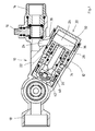
- a valve 10 is shown with a pressure reducer 12.
- the fitting 10 includes an inlet 14 for connection to a drinking water supply (not shown).
- the inlet 14 is shut off with a stopcock 16.
- Between the stopcock 16 and an outlet 18 of the generally designated 12 pressure reducer is provided.
- the pressure reducer 12 is arranged in a housing part 20 formed on the fitting housing 22.
- the water flows from the inlet 14 through a channel 24 in an input chamber 26.
- the housing part 20 is tubular, wherein the center axis forms an angle with the center axis of the remaining housing.
- a cylindrical strainer 28 is arranged, which covers the input chamber 26 of the channel 24.
- the housing part 20 is provided at one end 30 with a removable lid 32. In this way, the interior of the tubular housing part 20 is e.g. For maintenance or replacement of the pressure reducer accessible.
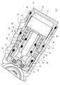
- the pressure reducer comprises a housing-fixed valve disk assembly and a movable valve seat body assembly ( Figure 2).
- the housing-fixed valve disc assembly comprises a valve stem 34.
- the valve stem 34 is elongate and provided with an axial center bore 36.
- the central bore 36 opens on the inlet side in the inlet chamber 26th
- a pot-shaped spring abutment body 38 is provided concentrically around the valve spindle, which is screwed onto the valve spindle 34.
- the spring abutment body 38 also has a passage in the region of the bore 36.
- the other, outlet-side end 40 of the valve stem 34 is slightly widened.
- This head so formed acting as a valve disc sealing member 42 is screwed.
- the sealing means cooperates with a seal 44 which is arranged in an annular groove in the head 40 of the valve spindle 34.
- a seal 46 is arranged in the form of an O-ring.
- the spring abutment body 38 is provided with a downstream open, deep annular groove 48.
- annular groove 48 Through the annular groove 48 two concentric cylindrical walls 52 and 54 are formed.
- a coil spring 50 is arranged, which is supported at the end of the annular groove 48 in the spring abutment body 38.
- the spring abutment body is sealed with a seal 58 against the housing 20 and screwed thereto.
- there is atmospheric pressure since it is connected via an opening 51 to the outer space of the housing.
- the spring 52 acts on the valve seat assembly. This is movably guided on the housing-fixed valve spindle 34.
- the valve seat assembly comprises a sliding sleeve 60 and a valve seat body 62 screwed onto it.
- the valve seat body 62 is cup-shaped and acts together with the valve disk 42 as a control valve. Between valve seat body 62 and sliding sleeve 60, a seal 64 is arranged.
- the sliding sleeve 60 is substantially tubular. It is guided with the upstream part on the valve stem 34 and sealed with a seal 66 against it.
- the inner diameter of the sliding sleeve 62 widens in the region of the head of the valve spindle 34. As a result, a cavity 68 is formed in the area in front of the valve between the valve spindle 34 and the sliding sleeve 62.
- the coil spring 52 presses against the sliding sleeve.
- the sliding sleeve has on the outside an annular groove in which a seal 70 is provided, with which the sliding sleeve is sealed relative to the housing 20.
- the valve spindle 34 has a radially extending transverse bore 72 in front of the region of the head. This is also shown in Fig. 4, which shows a further embodiment, in another section. About the transverse bore 72 and the channel 36, the space in front of the valve with the input chamber 26 is in communication.
- the pressure reducer works as follows:
- the outlet pressure in the outlet counteracts the annular, outer face of the valve seat body 62 of the force of the coil spring 52.
- the annular gap of the control valve between the fixed valve plate 42 and the valve seat 74 of the valve seat body 62 is throttled.
- the force of the coil spring 50 overcomes the discharge pressure and moves the valve seat assembly to the upper left in Fig.1, ie away from the fixed valve plate 42.
- the annular gap is increased, so that the outlet pressure can rise again. This situation is shown in FIG.
- the output pressure acting on the valve disk is received by the valve spindle 34 and by the latter from the housing.
- FIG. 4 The embodiment shown in Figures 1 to 3 shows a variant in which the entire pressure reducer assembly is installed at an angle in a valve. The arrangement is thus accessible via the lid 32 at any time. However, the fitting can be installed directly in a pipeline with appropriate dimensioning. This is shown in FIG. 4.
- inlet and outlet 78 are provided at the respective ends of the pressure reducer assembly 80, a linear arrangement can be achieved without providing lateral channels.
Landscapes
- Engineering & Computer Science (AREA)
- General Engineering & Computer Science (AREA)
- Mechanical Engineering (AREA)
- Physics & Mathematics (AREA)
- Fluid Mechanics (AREA)
- Details Of Valves (AREA)
- Safety Valves (AREA)
- Control Of Fluid Pressure (AREA)
Applications Claiming Priority (1)
| Application Number | Priority Date | Filing Date | Title |
|---|---|---|---|
| DE200510052385 DE102005052385B4 (de) | 2005-10-31 | 2005-10-31 | Druckminderer |
Publications (2)
| Publication Number | Publication Date |
|---|---|
| EP1780452A2 true EP1780452A2 (fr) | 2007-05-02 |
| EP1780452A3 EP1780452A3 (fr) | 2007-11-28 |
Family
ID=37663350
Family Applications (1)
| Application Number | Title | Priority Date | Filing Date |
|---|---|---|---|
| EP20060120367 Withdrawn EP1780452A3 (fr) | 2005-10-31 | 2006-09-08 | Réducteur de pression |
Country Status (5)
| Country | Link |
|---|---|
| US (1) | US20070095402A1 (fr) |
| EP (1) | EP1780452A3 (fr) |
| AU (1) | AU2006230770A1 (fr) |
| DE (1) | DE102005052385B4 (fr) |
| ZA (1) | ZA200608993B (fr) |
Cited By (5)
| Publication number | Priority date | Publication date | Assignee | Title |
|---|---|---|---|---|
| FR2917147A1 (fr) * | 2007-06-11 | 2008-12-12 | Perolo Sa Sa | Soupape de securite et conteneur-citerne equipe d'une telle soupape |
| DE102009030182A1 (de) * | 2009-06-24 | 2011-01-05 | Neoperl Gmbh | Ventil |
| EP2515021A3 (fr) * | 2011-04-18 | 2012-12-26 | Hans Sasserath & Co Kg | Agencement de filtre de réduction de pression doté d'une protection anti-fuites |
| CN108426044A (zh) * | 2018-03-29 | 2018-08-21 | 卢星霖 | 双阀体芯管阀 |
| CN108488403A (zh) * | 2018-03-29 | 2018-09-04 | 卢星霖 | 芯管阀 |
Families Citing this family (3)
| Publication number | Priority date | Publication date | Assignee | Title |
|---|---|---|---|---|
| CN102966774A (zh) * | 2012-11-14 | 2013-03-13 | 金祖贻 | 减压阀 |
| US9518670B2 (en) * | 2013-03-15 | 2016-12-13 | David E Albrecht | Main stage in-line pressure control cartridge with stepped retainer collar |
| CA2989323A1 (fr) * | 2015-06-14 | 2016-12-22 | David E. Albrecht | Cartouche de regulation de pression en ligne d'etage principal ayant un collier de retenue etage |
Citations (4)
| Publication number | Priority date | Publication date | Assignee | Title |
|---|---|---|---|---|
| FR1216484A (fr) | 1958-11-27 | 1960-04-26 | Détendeur pour gaz comprimés ou liquéfiés ou tous autres fluides | |
| DE3504785A1 (de) | 1984-03-01 | 1985-10-17 | Barmag Barmer Maschinenfabrik Ag, 5630 Remscheid | Druckregelventil |
| FR2754584A1 (fr) | 1996-10-15 | 1998-04-17 | Comap Sdh | Reducteur de pression pour installation de distribution de fluide |
| EP1431857A2 (fr) | 2002-12-17 | 2004-06-23 | Hans Sasserath & Co Kg | Bloc détendeur |
Family Cites Families (6)
| Publication number | Priority date | Publication date | Assignee | Title |
|---|---|---|---|---|
| US1038527A (en) * | 1912-02-24 | 1912-09-17 | Conrad Hubert | Needle-valve. |
| US3131715A (en) * | 1962-06-08 | 1964-05-05 | Lawrence M Sanders | Hydraulic braking accessory |
| DE4237451A1 (de) * | 1992-11-06 | 1994-05-11 | Teves Gmbh Alfred | Hydraulisches Druckminderventil |
| US5685297A (en) * | 1996-02-13 | 1997-11-11 | Schuler; Manfred | Freeze resistant liquid filled first stage scuba regulator |
| KR100215236B1 (ko) * | 1996-06-17 | 1999-08-16 | 오상수 | 차량 구동력 제어용 유압 공급장치 |
| US20040007269A1 (en) * | 2002-07-12 | 2004-01-15 | Larsen Todd W. | Inline pressure reducing regulator |
-
2005
- 2005-10-31 DE DE200510052385 patent/DE102005052385B4/de not_active Expired - Fee Related
-
2006
- 2006-09-08 EP EP20060120367 patent/EP1780452A3/fr not_active Withdrawn
- 2006-10-24 AU AU2006230770A patent/AU2006230770A1/en not_active Abandoned
- 2006-10-30 US US11/590,138 patent/US20070095402A1/en not_active Abandoned
- 2006-10-30 ZA ZA200608993A patent/ZA200608993B/xx unknown
Patent Citations (4)
| Publication number | Priority date | Publication date | Assignee | Title |
|---|---|---|---|---|
| FR1216484A (fr) | 1958-11-27 | 1960-04-26 | Détendeur pour gaz comprimés ou liquéfiés ou tous autres fluides | |
| DE3504785A1 (de) | 1984-03-01 | 1985-10-17 | Barmag Barmer Maschinenfabrik Ag, 5630 Remscheid | Druckregelventil |
| FR2754584A1 (fr) | 1996-10-15 | 1998-04-17 | Comap Sdh | Reducteur de pression pour installation de distribution de fluide |
| EP1431857A2 (fr) | 2002-12-17 | 2004-06-23 | Hans Sasserath & Co Kg | Bloc détendeur |
Cited By (9)
| Publication number | Priority date | Publication date | Assignee | Title |
|---|---|---|---|---|
| FR2917147A1 (fr) * | 2007-06-11 | 2008-12-12 | Perolo Sa Sa | Soupape de securite et conteneur-citerne equipe d'une telle soupape |
| EP2003380A1 (fr) * | 2007-06-11 | 2008-12-17 | Perolo S.A. | Soupape de sécurité et conteneur-citerne équipé d'une telle soupape |
| DE102009030182A1 (de) * | 2009-06-24 | 2011-01-05 | Neoperl Gmbh | Ventil |
| WO2010149313A3 (fr) * | 2009-06-24 | 2011-04-21 | Neoperl Gmbh | Soupape |
| US8919373B2 (en) | 2009-06-24 | 2014-12-30 | Neoperl Gmbh | Valve |
| EP2515021A3 (fr) * | 2011-04-18 | 2012-12-26 | Hans Sasserath & Co Kg | Agencement de filtre de réduction de pression doté d'une protection anti-fuites |
| CN108426044A (zh) * | 2018-03-29 | 2018-08-21 | 卢星霖 | 双阀体芯管阀 |
| CN108488403A (zh) * | 2018-03-29 | 2018-09-04 | 卢星霖 | 芯管阀 |
| CN108426044B (zh) * | 2018-03-29 | 2019-07-05 | 卢星霖 | 双阀体芯管阀 |
Also Published As
| Publication number | Publication date |
|---|---|
| EP1780452A3 (fr) | 2007-11-28 |
| ZA200608993B (en) | 2008-06-25 |
| AU2006230770A1 (en) | 2007-05-17 |
| US20070095402A1 (en) | 2007-05-03 |
| DE102005052385A1 (de) | 2007-05-24 |
| DE102005052385B4 (de) | 2008-07-10 |
Similar Documents
| Publication | Publication Date | Title |
|---|---|---|
| DE2450094A1 (de) | Schieber | |
| EP0487944B1 (fr) | Soupape de sécurité | |
| DE4310232C2 (de) | Notabschaltventil mit Regulator | |
| EP2527700A1 (fr) | Soupape | |
| DE102005052385B4 (de) | Druckminderer | |
| EP0401468B1 (fr) | Dispositif de soupape pour ouvrir et fermer en même temps deux conduites séparées de gaz ou de liquides | |
| DE2926320C2 (de) | Elektromagnetisch betätigtes Membran-Wasserventil mit einer hydraulischen Servoeinheit für die Regelung des Wasserkreislaufes in Heiz- bzw. Klimaanlagen | |
| EP2644788B1 (fr) | Agencement de séparation de tuyaux | |
| DE19824630B4 (de) | Ventilkombination aus einem Membranregler, einer Drossel und einem Regelventil | |
| EP1852642B1 (fr) | Soupape de sécurité | |
| EP1429064A1 (fr) | Electrovanne pilote | |
| EP0151563A2 (fr) | Electrovanne | |
| EP3561350B1 (fr) | Soupape de sécurité à vide | |
| DE19705200C1 (de) | Rückschlagventil | |
| EP0353266A1 (fr) | Clapet de non-retour, notamment pour conduits d'eau potable | |
| EP2644789B1 (fr) | Ensemble modulaire d'un agencement de séparation de tuyaux | |
| DE202012101123U1 (de) | Rohrtrenneranordnung | |
| DE19636410B4 (de) | Armatur für Wasserleitungen | |
| DE2259079B1 (de) | Ventil, insbesondere schwimmergesteuerter Kondensatableiter | |
| DE2503302A1 (de) | Schwimmergesteuertes ventil | |
| EP1503123B1 (fr) | Partie supérieure de soupape | |
| CH642434A5 (de) | Ventil. | |
| DE29517768U1 (de) | Wegeventil zur Steuerung eines Druckmittelstroms | |
| DE10045120B4 (de) | Flaschenverschlussvorrichtung | |
| DE10259205A1 (de) | Druckminderer-Baugruppe |
Legal Events
| Date | Code | Title | Description |
|---|---|---|---|
| PUAI | Public reference made under article 153(3) epc to a published international application that has entered the european phase |
Free format text: ORIGINAL CODE: 0009012 |
|
| AK | Designated contracting states |
Kind code of ref document: A2 Designated state(s): AT BE BG CH CY CZ DE DK EE ES FI FR GB GR HU IE IS IT LI LT LU LV MC NL PL PT RO SE SI SK TR |
|
| AX | Request for extension of the european patent |
Extension state: AL BA HR MK YU |
|
| PUAL | Search report despatched |
Free format text: ORIGINAL CODE: 0009013 |
|
| AK | Designated contracting states |
Kind code of ref document: A3 Designated state(s): AT BE BG CH CY CZ DE DK EE ES FI FR GB GR HU IE IS IT LI LT LU LV MC NL PL PT RO SE SI SK TR |
|
| AX | Request for extension of the european patent |
Extension state: AL BA HR MK YU |
|
| 17P | Request for examination filed |
Effective date: 20071221 |
|
| 17Q | First examination report despatched |
Effective date: 20080124 |
|
| AKX | Designation fees paid |
Designated state(s): AT BE BG CH CY CZ DE DK EE ES FI FR GB GR HU IE IS IT LI LT LU LV MC NL PL PT RO SE SI SK TR |
|
| STAA | Information on the status of an ep patent application or granted ep patent |
Free format text: STATUS: THE APPLICATION IS DEEMED TO BE WITHDRAWN |
|
| 18D | Application deemed to be withdrawn |
Effective date: 20100401 |