EP1780459A1 - Vorrichtung zum Abdichten von Muffen und undichten Pressverbindungen - Google Patents
Vorrichtung zum Abdichten von Muffen und undichten Pressverbindungen Download PDFInfo
- Publication number
- EP1780459A1 EP1780459A1 EP06405448A EP06405448A EP1780459A1 EP 1780459 A1 EP1780459 A1 EP 1780459A1 EP 06405448 A EP06405448 A EP 06405448A EP 06405448 A EP06405448 A EP 06405448A EP 1780459 A1 EP1780459 A1 EP 1780459A1
- Authority
- EP
- European Patent Office
- Prior art keywords
- counterpart
- sleeve
- pressure piece
- parts
- pipe
- Prior art date
- Legal status (The legal status is an assumption and is not a legal conclusion. Google has not performed a legal analysis and makes no representation as to the accuracy of the status listed.)
- Granted
Links
- 238000007789 sealing Methods 0.000 title claims description 60
- 239000011324 bead Substances 0.000 claims description 9
- 238000000034 method Methods 0.000 claims description 2
- 230000006835 compression Effects 0.000 description 11
- 238000007906 compression Methods 0.000 description 11
- 239000007789 gas Substances 0.000 description 4
- 229910052751 metal Inorganic materials 0.000 description 4
- 239000002184 metal Substances 0.000 description 4
- 238000000926 separation method Methods 0.000 description 4
- 244000089486 Phragmites australis subsp australis Species 0.000 description 3
- 230000002950 deficient Effects 0.000 description 3
- 239000007788 liquid Substances 0.000 description 3
- 239000004033 plastic Substances 0.000 description 3
- 238000003825 pressing Methods 0.000 description 3
- 238000005520 cutting process Methods 0.000 description 2
- 229920001971 elastomer Polymers 0.000 description 2
- 238000009434 installation Methods 0.000 description 2
- 238000004519 manufacturing process Methods 0.000 description 2
- 239000003566 sealing material Substances 0.000 description 2
- 230000007704 transition Effects 0.000 description 2
- 229910001369 Brass Inorganic materials 0.000 description 1
- 244000025254 Cannabis sativa Species 0.000 description 1
- 235000012766 Cannabis sativa ssp. sativa var. sativa Nutrition 0.000 description 1
- 235000012765 Cannabis sativa ssp. sativa var. spontanea Nutrition 0.000 description 1
- 229910000669 Chrome steel Inorganic materials 0.000 description 1
- 229910000831 Steel Inorganic materials 0.000 description 1
- 239000004809 Teflon Substances 0.000 description 1
- 229920006362 Teflon® Polymers 0.000 description 1
- 229910052782 aluminium Inorganic materials 0.000 description 1
- XAGFODPZIPBFFR-UHFFFAOYSA-N aluminium Chemical compound [Al] XAGFODPZIPBFFR-UHFFFAOYSA-N 0.000 description 1
- 239000010951 brass Substances 0.000 description 1
- 235000009120 camo Nutrition 0.000 description 1
- 235000005607 chanvre indien Nutrition 0.000 description 1
- 239000004020 conductor Substances 0.000 description 1
- 230000008878 coupling Effects 0.000 description 1
- 238000010168 coupling process Methods 0.000 description 1
- 238000005859 coupling reaction Methods 0.000 description 1
- 230000001419 dependent effect Effects 0.000 description 1
- 238000006073 displacement reaction Methods 0.000 description 1
- 238000005553 drilling Methods 0.000 description 1
- 230000005489 elastic deformation Effects 0.000 description 1
- 239000000806 elastomer Substances 0.000 description 1
- 230000002349 favourable effect Effects 0.000 description 1
- 239000000835 fiber Substances 0.000 description 1
- 238000010438 heat treatment Methods 0.000 description 1
- 239000011487 hemp Substances 0.000 description 1
- 239000000463 material Substances 0.000 description 1
- 231100000614 poison Toxicity 0.000 description 1
- 239000010959 steel Substances 0.000 description 1
- 239000003440 toxic substance Substances 0.000 description 1
- 238000003466 welding Methods 0.000 description 1
Images


Classifications
-
- F—MECHANICAL ENGINEERING; LIGHTING; HEATING; WEAPONS; BLASTING
- F16—ENGINEERING ELEMENTS AND UNITS; GENERAL MEASURES FOR PRODUCING AND MAINTAINING EFFECTIVE FUNCTIONING OF MACHINES OR INSTALLATIONS; THERMAL INSULATION IN GENERAL
- F16L—PIPES; JOINTS OR FITTINGS FOR PIPES; SUPPORTS FOR PIPES, CABLES OR PROTECTIVE TUBING; MEANS FOR THERMAL INSULATION IN GENERAL
- F16L13/00—Non-disconnectable pipe joints, e.g. soldered, adhesive, or caulked joints
- F16L13/14—Non-disconnectable pipe joints, e.g. soldered, adhesive, or caulked joints made by plastically deforming the material of the pipe, e.g. by flanging, rolling
- F16L13/141—Non-disconnectable pipe joints, e.g. soldered, adhesive, or caulked joints made by plastically deforming the material of the pipe, e.g. by flanging, rolling by crimping or rolling from the outside
- F16L13/142—Non-disconnectable pipe joints, e.g. soldered, adhesive, or caulked joints made by plastically deforming the material of the pipe, e.g. by flanging, rolling by crimping or rolling from the outside with a sealing element inserted into the female part before crimping or rolling
-
- F—MECHANICAL ENGINEERING; LIGHTING; HEATING; WEAPONS; BLASTING
- F16—ENGINEERING ELEMENTS AND UNITS; GENERAL MEASURES FOR PRODUCING AND MAINTAINING EFFECTIVE FUNCTIONING OF MACHINES OR INSTALLATIONS; THERMAL INSULATION IN GENERAL
- F16L—PIPES; JOINTS OR FITTINGS FOR PIPES; SUPPORTS FOR PIPES, CABLES OR PROTECTIVE TUBING; MEANS FOR THERMAL INSULATION IN GENERAL
- F16L19/00—Joints in which sealing surfaces are pressed together by means of a member, e.g. a swivel nut, screwed on, or into, one of the joint parts
-
- F—MECHANICAL ENGINEERING; LIGHTING; HEATING; WEAPONS; BLASTING
- F16—ENGINEERING ELEMENTS AND UNITS; GENERAL MEASURES FOR PRODUCING AND MAINTAINING EFFECTIVE FUNCTIONING OF MACHINES OR INSTALLATIONS; THERMAL INSULATION IN GENERAL
- F16L—PIPES; JOINTS OR FITTINGS FOR PIPES; SUPPORTS FOR PIPES, CABLES OR PROTECTIVE TUBING; MEANS FOR THERMAL INSULATION IN GENERAL
- F16L55/00—Devices or appurtenances for use in, or in connection with, pipes or pipe systems
- F16L55/16—Devices for covering leaks in pipes or hoses, e.g. hose-menders
- F16L55/168—Devices for covering leaks in pipes or hoses, e.g. hose-menders from outside the pipe
- F16L55/178—Devices for covering leaks in pipes or hoses, e.g. hose-menders from outside the pipe by clamping an outer gasket against a joint with sleeve or socket
Definitions
- the invention relates to a device for sealing leaky sleeves and press connections, according to the preamble of independent claim 1.
- pipes for the transport of gases and liquids are usually connected by means of sleeves.
- the tubes are wrapped with a sealing material, eg hemp fibers, and inserted into the sleeve.
- the sealing material swells up by absorbing moisture and seals the sleeve connection.
- the sleeve and the pipe are heated and welded by means of an inserted in this so-called. Welding sleeve conductor.
- the pipes are usually connected to press sleeves today. In such press connections or press fittings, a metal tube is inserted into a plastically deformable metal sleeve.
- This sleeve has a hollow bead at the longitudinal ends, in which a sealing ring made of an elastomer is inserted.
- a sealing ring made of an elastomer is inserted.
- Such a press connection is shown for example in EP 1'505'329 A2.
- the sleeve is then pressed with the tube. This leads firstly to a positive and non-positive connection of the sleeve and pipe, and on the other hand to a tight completion of the connection by an elastic deformation of the sealing ring in the bead. Due to incorrect manipulations, it may happen that the sealing ring of the compression sleeve is damaged.
- the object of the invention is to provide a sealing device of the type mentioned above, with which leaky sleeves and press connections can be sealed and repaired quickly and permanently during operation of the conduit system and without costly replacement of the connection.
- the principle of a sealing device according to the invention is based on the fact that a leaky socket connection is re-sealed at the point of entry of the pipe into the sleeve over the entire circumference of the pipe.
- the inventive device consists of a pipe circumference comprehensive pressure element, with which an additional seal is pressed onto the space between the sleeve and pipe, and a sleeve body comprehensive counterpart, by means of which the pressure piece are pulled in the direction of the sleeve body and positive and non-positive can be fixed.
- the pressure piece of a sealing device has substantially the shape of a hollow cylinder with an external thread, with an inner diameter which is equal to or slightly larger than the outer diameter of the tube, and an outer diameter which is greater than the maximum diameter of the sleeve.
- the counterpart also has essentially the shape of a hollow cylinder. Over a part of the length of the counterpart, the inner diameter corresponds to the diameter of a sleeve between the brieflywülsten. This area later encloses the sleeve. Over the remaining length, the counterpart has an internal thread with the same diameter as the external thread of the An Kunststoffs.
- pressure piece and counterpart of a sealing device according to the invention can be mounted around the completely installed pipe or around the sleeve, they must each consist of at least two half shells, which have an opening angle of at most 180 °.
- the at least two parts of the counterpart must be connected to each other positively and / or non-positively.
- the at least two parts need not necessarily be connected to each other, since these are fixed by screwing by themselves to each other,
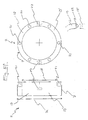
- FIG. 1 shows such a press connection in longitudinal section.
- a tube 5 in a compression sleeve 4 also called press fitting
- This press sleeve 4 which has at its end a bead 8 with sealing ring 9 inserted therein, is subsequently irreversibly pressed by means of a suitable tool with the tube 5.
- the sealing ring 9 is pressed flush with the tube 5, the press connection is sealed.
- the sealing ring 9 is damaged, for example, during assembly, there may be a leak 11.
- Liquid or gas can then flow under pressure from the interior of the tube 5 between the pipe and sleeve through the leak, and exit on the front side 10 of the sleeve 4.
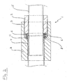
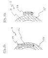
- FIG. 2 shows a longitudinal section of a possible embodiment of a sealing device 1 according to the invention, with a pressure piece 2 and a counterpart 3.
- a seal 6 was attached to the front side of the sleeve 4. This seal can not be a conventional, closed sealing ring, because it can not be pushed onto the tube 5 yes.
- the easiest way the seal 6 is created by wrapping the tube 5 with sealing cord, such as rubber cord or Teflon cord with eg 2 mm diameter.
- a modified sealing ring may be used, consisting of a severed sealing ring. Its cut-through surface is designed such that the two ends of the severed ring overlap with respect to the ring plane.
- Such a sealing ring can now be easily attached to the leaky sleeve. Upon later compression of the gasket perpendicular to the plane of the ring, the severing surfaces are then pressed together and the gasket is sealed.
- a plurality of separated by simple cutting sealing rings can be arranged one above the other on the pipe so that the interfaces are offset from each other.
- the pressure piece 2, which comprises the tube 5 is screwed into the counterpart 3 comprising the sleeve 4. On the inside of the counterpart 3 this is on the bead 8 of the sleeve 4.
- By screwing the An für Industriess 2 then the previously mounted seal 6 is pressed against the tube 5 and the front of the sleeve 4. This results in a seal of the gap between the bead 8 and tube 5.
- the press connection is permanently sealed and repaired.
- the pressure piece 2 and the counterpart 3 may be made of metal, in particular aluminum, steel, brass or chrome steel. Also possible is a production of a suitable plastic.
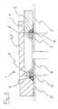
- Figures 3a and 3b show the counterpart 3 of Figure 2 in longitudinal section and seen from the pressure piece 2 opposite longitudinal end ago.
- the sectional plane of FIG. 3a is perpendicular to the sectional plane in FIG. 2.
- the counterpart is composed of a first part 12a and a second part 12b.
- the two parts 12a, 12b In the region of the smaller inner diameter 13, the two parts 12a, 12b have teeth 15, 15a which engage in one another and thus fix the position of the two parts relative to one another in the longitudinal direction.
- the teeth 15 In order for the second part 12b to be slipped over a sleeve, the teeth 15 have vertical walls, which is shown in FIG. 3b by the dashed lines.
- a bore 20 is mounted through which a pin 14 is inserted after attachment to the pipe sleeve.
- the diameter 16 of the internal thread 7 must be greater than the maximum diameter of a sleeve at the bead.
- two recesses 17 are attached to which, for example, a pipe wrench can attack.
- four or six recesses 17 could be used instead of two.
- one end of the counterpart 3 would have the shape of a hexagon nut. It is also conceivable to make the counterpart hexagonal over the entire length.
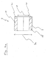
- Figures 4a and 4b show the An horrying 2 of Figure 2 in longitudinal section and seen from the counterpart 3 opposite longitudinal end ago.
- the sectional plane of FIG. 4a again stands perpendicular to the sectional plane in FIG. 2.
- the pressure piece 2 consists of two essentially identical parts 19, 19 '. These are not interconnected. However, these are automatically fixed in position to each other when screwed into the counterpart 3.
- the diameter 7a of the external thread corresponds to the internal thread of the counterpart 3.
- Der Inner diameter 18 substantially corresponds to the outer diameter of the tube. Both parts are provided with a bore 21 into which a key can engage with corresponding cams in order to screw the pressure piece 2 into the counterpart 3.
- FIG. 5 shows a further embodiment of a counterpart 3 for a sealing device according to the invention, in a longitudinal section, and viewed from the end opposite the pressure piece.
- both parts 12, 12 'of the counterpart 3 are made substantially identical, with only one tooth 15, 15a on each side.
- the pins 14 are arranged symmetrically opposite each other through the teeth 15, 15a.
- the teeth 15, 15a are in turn equipped with straight walls.
- the recesses 17 extend over a majority of the threadless area. Both the threadless area and the thread 7 are shorter compared to the diameter of the counterpart 3 as in the design example of Figures 2, 3a and 3b.
- the transition region between the threaded portion and the threadless portion is formed perpendicular to the longitudinal axis, and not conical.
- An advantage of the counterpart 3 in Figure 5 is the fact that two identical parts 12, 12 'can be used if a suitable thread is chosen.
- the shortened structure allows mounting in confined spaces.
- Figure 5a shows the drawing of a sealing device according to the invention in a disassembled state, with a two parts 19, 19 'existing Antik Federation 2 with external thread (not visible), consisting of two parts 12a, 12b counterpart 3, and two pins 14.
- the teeth 15th , 15a are designed analogously to the counterpart in Figure 3a, 3b.
- Figures 5b and 5c show the same sealing device 1 in partially assembled condition.
- the depressions 17 on the pressing piece 2 and on the counterpart 3 are clearly visible in FIG. 5 c.
- FIG. 5d shows a press connection consisting of compression sleeve 4 and tube 5, sealed by the sealing device 1 according to the invention from FIG. 5a, 5b, 5c.
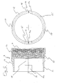
- FIG. 5e shows a further embodiment of a counterpart 3 for a sealing device according to the invention, viewed from the side and from the end opposite the pressure piece.
- both parts 12, 12 'of the counterpart 3 are designed substantially identical.
- the two parts 12, 12 ' are positively and non-positively connected by screws 23.
- Allen screws are used in the example shown, but of course other suitable screws can be chosen.
- the teeth 15, 15a are equipped with straight walls.
- the transition region between the threaded portion with thread diameter 16 and the unthreaded portion with inner diameter 13 is conical.
- six radial holes 21 are arranged.
- FIG. 5f shows a further embodiment of a pressure piece 2 for a sealing device according to the invention, seen from the side and from the opposite end from the counterpart.
- the two parts 19, 19 ' are substantially identical. Parallel to the plane of separation of the parts they are immovably fixed by two cams 22 which engage in corresponding recesses of a part.
- the cams can all be on be attached to a part. However, it is advantageous to attach a cam 22 on each part, since both parts 19, 19 'are identical.
- Figures 6a and 6b show schematically in cross-section two further possibilities for positive and non-positive connection of two parts 12a, 12b of a counterpart 3.
- the two parts are connected by screws 23rd Teeth are not necessary in such an embodiment.
- the screw 23 passes through two outer brackets, which are formed on identical parts 12, 12 '. Secured is the screw with a nut.
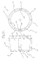
- FIG. 7 shows a further embodiment of a counterpart 3 for a sealing device according to the invention, seen from the end opposite the pressure piece.
- the two parts 12, 12 ' are substantially identical. Parallel to the plane of separation of the parts they are immovably fixed by cams 22 which engage in corresponding recesses of a part. The cams can all be distributed on one part or on both parts.
- the two parts comprising one or more bridges or clamps 25 are attached, which hold the parts perpendicular to the separation plane. It is even possible to use cable ties.
- This embodiment has the advantage that it is simple and therefore inexpensive to manufacture.
- FIG. 8 shows in longitudinal section a further embodiment of a pressure piece 2 of a sealing device according to the invention.
- the two parts are mutually protected with cam 22 against displacement parallel to the plane of separation between the two equal parts 19, 19 '.
- FIG. 9 shows a longitudinal section of a further embodiment of a sealing device 1 according to the invention.
- the rollers of the counterpart 3 and of the pressure piece 2 are reversed.
- the Anyak Gland 2 has an internal thread, and the counterpart 3 via an external thread.
- the at least two parts of the An für Swisss 2 must be positively and non-positively connected.
- the variants for counterpart and pressure piece shown can also be used analogously for this embodiment of a sealing device according to the invention shown.
- Figure 10 shows in longitudinal section a sealing device according to the invention 1 for sealing a sleeve or press connection with two leaking seals 9.
- the two attached to the opposite ends of the sleeve 4 An horrying Federatione 2, 2 'are of identical design and differ only by the opposite direction of the External thread 7a or 7b.
- the counterpart 3 has at its opposite ends on corresponding opposing internal thread.
- FIG. 11 shows a longitudinal section of another embodiment of a sealing device 1 according to the invention for sealing a sleeve or press connection with two leaky seals 9.
- the counterpart 3 simultaneously serves as the second pressure piece 2 '.
- the most space-saving design of a sealing device according to the invention is advantageous.
- the Antik choir be made very short, for example, with a length of only 5 mm.
- the external thread then has only a few passages. Analogously, the counterpart can be made very short.
Landscapes
- Engineering & Computer Science (AREA)
- General Engineering & Computer Science (AREA)
- Mechanical Engineering (AREA)
- Electrical Discharge Machining, Electrochemical Machining, And Combined Machining (AREA)
- Joints With Pressure Members (AREA)
- Gasket Seals (AREA)
- Quick-Acting Or Multi-Walled Pipe Joints (AREA)
- Pipe Accessories (AREA)
Abstract
Description
- Die Erfindung betrifft eine Vorrichtung zum Abdichten von undichten Muffen und Pressverbindungen, gemäss dem Oberbegriff des unabhängigen Anspruchs 1.
- Bei der Installation werden Rohre für den Transport von Gasen und Flüssigkeiten in der Regel mittels Muffen verbunden. Bei einer althergebrachten Technik werden die Rohre mit einem Dichtungsmaterial, z.B. Hanffasern, umwickelt und in die Muffe eingeschoben. Das Dichtungsmaterial quillt durch Aufnahme von Feuchtigkeit auf und dichtet die Muffenverbindung ab. Bei einer modernen Lösung für Rohre aus Kunststoff werden die Muffe und das Rohr mittels eines in diese sog. Schweissmuffe eingelegten Stromleiters erhitzt und verschweisst.
Für die effiziente Installation von Rohrleitungen aus Metall werden die Rohre heute in aller Regel mit Pressmuffen verbunden. Bei solchen Pressverbindungen oder Pressfittings wird ein Metallrohr in eine plastisch verformbare Metallmuffe eingeschoben. Diese Muffe verfügt an den Längsenden über einen hohlen Wulst, in welchen ein Dichtungsring aus einem Elastomer eingelegt ist. Eine solche Pressverbindung wird beispielsweise gezeigt in EP 1'505'329 A2.
Mit einem speziell dafür vorgesehenen Werkzeug wird anschliessend die Muffe mit dem Rohr verpresst. Dies führt zum einen zu einer form- und kraftschlüssigen Verbindung von Muffe und Rohr, und zum anderen zu einem dichten Abschluss der Verbindung durch eine elastische Verformung des Dichtungsrings im Wulst.
Durch Fehlmanipulationen kann es vorkommen, dass der Dichtungsring der Pressmuffe beschädigt wird. Nach dem Verpressen ist dann die Pressverbindung nicht dicht Ebenso ist es möglich, dass unbemerkt ein Rohr beschädigt wird, beispielsweise beim Ablängen mittels einer Säge, was ebenfalls zu einer lecken Muffenverbindung führen kann. Der Kunststoff der Dichtungsringe kann zudem altem und dabei spröde und rissig werden. In einiger Zukunft ist deshalb eventuell vermehrt mit undichten Pressverbindungen zu rechnen. - Da ein Leitungssystem normalerweise erst nach der endgültigen Erstellung befüllt wird, können etwaige Lecks oft erst nach Abschluss der Montage entdeckt und repariert werden. Während für die Reparatur von Lecks von Rohren während des Betriebs, also ohne Auswechseln des defekten Rohres, Lösungen bekannt sind, müssen defekte Muffenverbindungen, insbesondere Pressverbindungen, komplett ausgetauscht werden. Dazu muss das Leitungssystem entleert werden, was bei grösseren Systemen wie beispielsweise Heizungsanlagen von grösseren Gebäuden einige Zeit in Anspruch nehmen kann. Bei gewissen Systemen, beispielsweise Klimaanlagen, kann zudem der Leitungsinhalt nicht einfach in die Kanalisation abgelassen werden, da er toxische Substanzen enthält, und muss darum aufgefangen werden. Nach der Entleerung muss die defekte Muffe entfernt werden, was nur durch absägen möglich ist. Für die Reparatur sind dann schon in den einfacheren Fällen zwei Pressmuffen und ein Zwischenrohrstück erforderlich. Bei komplizierteren Fällen, beispielsweise bei T-Stücken, ist der Material- und Zeitaufwand noch grösser. Anschliessend an die Reparatur des Lecks muss das Leitungssystem wieder befüllt und dabei auch entlüftet werden, was ebenfalls viel Zeit in Anspruch nehmen kann. Es ist also durchaus möglich, dass die Reparatur einer einzigen undichten Pressmuffe mehrere Stunden in Anspruch nimmt.
- Aufgabe der Erfindung ist es, eine Abdichtungsvorrichtung der eingangs erwähnten Art zur Verfügung zu stellen, mit welcher undichte Muffen und Pressverbindungen während des Betriebs des Leitungssystems und ohne aufwendiges Auswechseln der Verbindung schnell und dauerhaft abgedichtet und repariert werden können.
- Diese und andere Aufgaben werden durch eine erfindungsgemässe Vorrichtung gemäss dem unabhängigen Anspruch gelöst. Weitere bevorzugte Ausführungsformen sind in den abhängigen Ansprüchen gegeben.
- Das Prinzip einer erfindungsgemässen Abdichtungsvorrichtung beruht darauf, dass eine undichte Muffenverbindung an der Eintrittsstelle des Rohrs in die Muffe über den gesamten Rohrumfang neu abgedichtet wird. Zu diesem Zweck besteht die erfindungsgemässe Vorrichtung aus einem den Rohrumfang umfassenden Andruckstück, mit welchem eine zusätzliche Dichtung auf den Zwischenraum zwischen Muffe und Rohr gedrückt wird, und einem den Muffenkörper umfassenden Gegenstück, mittels dem das Andruckstück in Richtung Muffenkörper gezogen werden und form- und kraftschlüssig fixiert werden kann.
Das Andruckstück einer erfindungsgemässen Abdichtungsvorrichtung weist im wesentlichen die Form eines Hohlzylinders mit einem Aussengewinde auf, mit einem Innendurchmesser, der gleich gross oder leicht grösser ist als der Aussendurchmesser des Rohres, und einem Aussendurchmesser, der grösser ist als der maximale Durchmesser der Muffe.
Das Gegenstück hat ebenfalls im wesentlichen die Form eines Hohlzylinders. Über einen Teil der Länge des Gegenstücks entspricht der Innendurchmesser dem Durchmesser einer Muffe zwischen den Aussenwülsten. Dieser Bereich umschliesst später die Muffe. Über die verbleibende Länge verfügt das Gegenstück über ein Innengewinde mit dem gleichen Durchmesser wie das Aussengewinde des Andruckstücks. Nachdem eine neue Dichtung angebracht worden ist, durch Umwickeln des Rohres mit Dichtungsschnur im Bereich des Muffenwulstes oder durch Anbringen eines geeignet modifizierten Dichtungsringes, wird das Andruckstück in das Gegenstück eingeschraubt, und drückt so die Dichtung auf die Lücke zwischen Rohr und Muffe. - Damit Andruckstück und Gegenstück einer erfindungsgemässen Abdichtungsvorrichtung um das fertig installierte Rohr bzw. um die Muffe herum montiert werden können, müssen sie jeweils aus mindestens zwei Halbschalen bestehen, welche einen Öffnungswinkel von maximal 180° aufweisen. Die mindestens zwei Teile des Gegenstücks müssen miteinander form- und/oder kraftschlüssig verbunden sein. Beim Andruckstück, welches in das Gegenstück eingeschraubt wird, müssen die mindestens zwei Teile nicht zwingend miteinander verbunden werden, da diese durch das Einschrauben von alleine aneinander fixiert werden,
Zusätzlich ist es von Vorteil, Andruckstück und Gegenstück mit Mitteln auszustatten, welche es erlauben, ein Drehmoment auf diese auszuüben. Möglich sind zum Beispiel Vertiefungen, an denen eine Zange angreifen kann, oder Ankopplungsstellen für spezielle Schlüssel. - Im folgenden wird die erfindungsgemässe Vorrichtung anhand von Zeichnungen erläutert.
- Figur 1 zeigt im Längsschnitt eine Pressverbindung, bestehend aus einer Pressmuffe mit eingeschobenem Rohr, bei welcher durch ein Leck in der Dichtung der Pressmuffe Flüssigkeit bzw. Gas austritt.
- Figur 2 zeigt im Längsschnitt die undichte Pressverbindung aus Figur 1, abgedichtet durch eine erfindungsgemässe Abdichtungsvorrichtung, im wesentlichen bestehend aus einem Andruckstück und einem Gegenstück.
- Figur 3a zeigt im Längsschnitt das Gegenstück der erfindungsgemässen Abdichtungsvorrichtung aus Figur 2, wobei die Schnittebene senkrecht zur Schnittebene in Figur 2 liegt.
- Figur 3b zeigt das Gegenstück aus Figur 3a, vom dem Andruckstück entgegengesetzten Längsende her gesehen.
- Figur 4a zeigt im Längsschnitt das Andruckstück der erfrndungsgemässen Abdichtungsvorrichtung aus Figur 2, wobei die Schnittebene senkrecht zur Schnittebene in Figur 2 liegt.
- Figur 4b zeigt das Andruckstück aus Figur 4a, vom dem Gegenstück entgegengesetzten Längsende her gesehen.
- Figur 5 zeigt eine weitere Gestaltungsform eines Gegenstücks für eine erfindungsgemässe Abdichtungsvorrichtung, im Längsschnitt und vom einem Andruckstück entgegengesetzten Längsende her gesehen.
- Figur 5a zeigt eine Zeichnung einer erfindungsgemässen Abdichtungsvorrichtung in zerlegtem Zustand, bestehend aus Andruckstück, Gegenstück und Stiften.
- Figur 5b zeigt das Gegenstück und das Andruckstück aus Figur 5a, in teilweise zusammengesetztem Zustand.
- Figur 5c zeigt eine weitere Zeichnung der erfindungsgemässen Abdichtungsvorrichtung aus Figur 5a, in zusammengesetztem Zustand.
- Figur 5d zeigt eine Zeichnung einer Pressmuffe mit eingeschobenem Rohr, abgedichtet durch die erfindungsgemässe Abdichtungsvorrichtung aus den Figuren 5a bis 5c.
- Figur 5e zeigt eine weitere Gestaltungsform eines Gegenstücks für eine erfindungsgemässe Abdichtungsvorrichtung, von der Seite her und vom einem Andruckstück entgegengesetzten Längsende her gesehen.
- Figur 5f zeigt eine weitere Gestaltungsform eines Andruckstücks für eine erfindungsgemässe Abdichtungsvorrichtung, von der Seite her und vom einem Gegenstück entgegengesetzten Längsende her gesehen.
- Figur 6a zeigt im Querschnitt eine mögliche Gestaltungsform der Verbindung zwischen den zwei Teilen eines Gegenstücks für eine erfindungsgemässe Abdichtungsvorrichtung.
- Figur 6b zeigt im Querschnitt eine weitere mögliche Gestaltungsform der Verbindung zwischen den zwei Teilen eines Gegenstücks für eine erfindungsgemässe Abdichtun gsvorrichtung.
- Figur 7 zeigt eine weitere mögliche Gestaltungsform eines Gegenstücks für eine erfindungsgemässe Abdichtungsvorrichtung, in Längsrichtung vom einem Andruckstück entgegengesetzten Längsende her gesehen.
- Figur 8 zeigt eine weitere mögliche Gestaltungsform eines Andruckstücks für eine erfindungsgemässe Abdichtungsvorrichtung, in Längsrichtung vom einem Gegenstück entgegengesetzten Längsende her gesehen.
- Figur 9 zeigt im Längsschnitt eine undichte Pressmuffe mit eingeschobenem Rohr, abgedichtet durch eine weitere Gestaltungsform einer erfindungsgemässen Abdichtungsvorrichtung.
- Figur 10 zeigt im Längsschnitt eine an zwei Enden undichte Pressmuffe mit zwei eingeschobenen Rohren, abgedichtet durch eine weitere Gestaltungsform einer erfindungsgemässen Abdichtungsvorrichtung.
- Figur 11 zeigt im Längsschnitt eine an zwei Enden undichte Pressmuffe mit zwei eingeschobenen Rohren, abgedichtet durch eine weitere Gestaltungsform einer erfindungsgemässen Abdichtungsvorrichtung.
- Die Probleme einer undichten Pressverbindung werden in Figur 1 ersichtlich, welche eine solche Pressverbindung im Längsschnitt zeigt. Beim Erstellen einer solchen Verbindung wird ein Rohr 5 in eine Pressmuffe 4, auch Pressfitting genannt, eingeschoben. Diese Pressmuffe 4, welche an ihrem Ende einen Wulst 8 mit darin eingelegtem Dichtungsring 9 aufweist, wird anschliessend mittels eines dafür geeigneten Werkzeugs mit dem Rohr 5 irreversibel verpresst. Dabei wird der Dichtungsring 9 bündig an das Rohr 5 gedrückt, die Pressverbindung ist dicht. Falls jedoch der Dichtungsring 9 beschädigt wird, beispielsweise bei der Montage, kann es zu einem Leck 11 kommen. Flüssigkeit oder Gas kann dann unter Druck aus dem Inneren des Rohres 5 zwischen Rohr und Muffe hindurch durch das Leck strömen, und an der Frontseite 10 der Muffe 4 austreten.
- Figur 2 zeigt im Längsschnitt eine mögliche Ausgestaltung einer erfindungsgemässen Abdichtungsvorrichtung 1, mit einem Andruckstück 2 und einem Gegenstück 3.
Vor der Montage der erfindungsgemässen Abdichtungsvorrichtung 1 wurde an der Frontseite der Muffe 4 eine Dichtung 6 angebracht. Diese Dichtung kann kein üblicher, geschlossener Dichtungsring sein, weil sie ja nicht auf das Rohr 5 aufgeschoben werden kann. Am einfachsten wird die Dichtung 6 durch Umwickeln des Rohres 5 mit Dichtungsschnur erstellt, beispielsweise Gummischnur oder Teflonschnur mit z.B. 2 mm Durchmesser.
Alternativ kann auch ein modifizierter Dichtungsring verwendet werden, bestehend aus einem durchtrennten Dichtungsring. Dessen Durchtrennungsfläche ist so ausgestaltet, dass mit Blick auf die Ringebene sich die beiden Enden des durchtrennten Rings überlappen. Ein derartiger Dichtungsring kann nun einfach an der undichten Muffe angebracht werden. Bei späteren Zusammenpressen der Dichtung senkrecht zur Ringebene werden dann die Durchtrennungsflächen aufeinander gedrückt, und die Dichtung ist dicht.
In einer weiteren Alternative können auch mehrere durch einfaches Zerschneiden aufgetrennte Dichtungsringe so übereinander auf dem Rohr angeordnet werden, dass die Schnittstellen zueinander versetzt sind.
Das Andruckstück 2, welches das Rohr 5 umfasst, ist in das die Muffe 4 umfassende Gegenstück 3 eingeschraubt. Auf der Innenseite des Gegenstücks 3 steht dieses auf dem Wulst 8 der Muffe 4 auf. Durch das Eindrehen des Andruckstücks 2 wird dann die zuvor angebrachte Dichtung 6 gegen das Rohr 5 und die Frontseite der Muffe 4 gedrückt. Daraus resultiert eine Abdichtung des Zwischenraums zwischen Wulst 8 und Rohr 5. Die Pressverbindung ist dauerhaft abgedichtet und repariert. - Das Andruckstück 2 und das Gegenstück 3 können aus Metall gefertigt sein, insbesondere Aluminium, Stahl, Messing oder Chromstahl. Möglich ist auch eine Fertigung aus einem geeignetem Kunststoff.
- Die Figuren 3a und 3b zeigen das Gegenstück 3 aus Figur 2 im Längsschnitt und vom dem Andruckstück 2 entgegengesetzten Längsende her gesehen. Die Schnittebene der Figur 3a steht dabei senkrecht zur Schnittebene in Figur 2. Das Gegenstück ist zusammengesetzt aus einem ersten Teil 12a und einem zweiten Teil 12b. Im Bereich des kleineren Innendurchmessers 13 weisen die beiden Teile 12a, 12b Zähne 15, 15a auf, welche ineinander greifen, und so die Position der beiden Teile zueinander in Längsrichtung fixieren. Damit das zweite Teil 12b über eine Muffe gestülpt werden kann, weisen die Zähne 15 senkrechte Wände auf, was in Figur 3b durch die gestrichelten Linien gezeigt wird. Zur form- und kraftschlüssigen Verbindung der beiden Teile 12a, 12b quer zur Längsachse ist auf beiden Seiten durchgehend durch die Zähne 15, 15a eine Bohrung 20 angebracht, durch die nach dem Anbringen an der Rohrmuffe je ein Stift 14 gesteckt wird. Dieser wird in einer vorteilhaften Variante am aussenliegenden Ende so ausgestaltet, dass er gegebenenfalls wieder entfernt werden kann. Der Durchmesser 16 des Innengewindes 7 muss grösser sein als der maximale Durchmesser einer Muffe am Wulst. Am dem Innengewinde 7 entgegengesetzten Ende des Gegenstücks 3 sind zwei Vertiefungen 17 angebracht, an denen beispielsweise eine Rohrzange angreifen kann.
In einer möglichen Variante könnten statt zwei auch vier oder sechs Vertiefungen 17 verwendet werden. Im letzteren Fall würde das eine Ende des Gegenstücks 3 die Form einer Sechskantmutter aufweisen. Denkbar ist auch, das Gegenstück über die gesamte Länge sechskantig auszuführen. - Die Figuren 4a und 4b zeigen das Andruckstück 2 aus Figur 2 im Längsschnitt und vom dem Gegenstück 3 entgegengesetzten Längsende her gesehen. Die Schnittebene der Figur 4a steht dabei wiederum senkrecht zur Schnittebene in Figur 2. Das Andruckstück 2 besteht aus zwei im wesentlichen identischen Teilen 19, 19'. Diese sind nicht miteinander verbunden. Jedoch werden diese beim Einschrauben in das Gegenstück 3 automatisch in der Position zueinander fixiert. Der Durchmesser 7a des Aussengewindes entspricht dem Innengewinde des Gegenstücks 3. Der Innendurchmesser 18 entspricht im wesentlichen dem Aussendurchmesser des Rohrs. Beide Teile sind mit einer Bohrung 21 versehen, in die ein Schlüssel mit entsprechenden Nocken eingreifen kann, um das Andruckstück 2 in das Gegenstück 3 einzudrehen.
- Figur 5 zeigt eine weitere Gestaltungsform für ein Gegenstück 3 für eine erfindungsgemässe Abdichtungsvorrichtung, in einem Längsschnitt, und vom dem Andruckstück entgegengesetzten Ende her gesehen. Im gezeigten Beispiel sind beide Teile 12, 12' des Gegenstücks 3 im wesentlichen identisch gestaltet, mit nur einem Zahn 15, 15a auf jeder Seite. Die Stifte 14 sind durchgehend durch die Zähne 15, 15a symmetrisch einander gegenüberliegend angeordnet. Die Zähne 15, 15a sind wiederum mit geraden Wänden ausgestattet. Die Vertiefungen 17 ziehen sich über einen Grossteil des gewindelosen Bereichs hin. Sowohl der gewindelose Bereich wie auch das Gewinde 7 sind kürzer im Vergleich zum Durchmesser des Gegenstücks 3 als im Gestaltungsbeispiel aus den Figuren 2, 3a und 3b. Der Übergangsbereich zwischen dem Gewindebereich und dem gewindelosen Bereich ist senkrecht zur Längsachse ausgeformt, und nicht konisch.
Ein Vorteil des Gegenstücks 3 in Figur 5 ist die Tatsache, dass zwei identische Teile 12, 12' verwendet werden können, falls ein passendes Gewinde gewählt wird. Zudem ermöglicht der verkürzte Aufbau eine Montage bei beengten Platzverhältnissen. - Figur 5a zeigt die Zeichnung einer erfindungsgemässen Abdichtungsvorrichtung in zerlegtem Zustand, mit einem aus zwei Teilen 19, 19' bestehenden Andruckstück 2 mit Aussengewinde (nicht sichtbar), einem aus zwei Teilen 12a, 12b bestehenden Gegenstück 3, und zwei Stiften 14. Die Zähne 15, 15a sind analog zum Gegenstück in Figur 3a, 3b gestaltet.
Die Figuren 5b und 5c zeigen die gleiche Abdichtungsvorrichtung 1 in teilweise zusammengebautem Zustand. In Figur 5c gut sichtbar sind die Vertiefungen 17 am Andruckstück 2 und am Gegenstück 3. - Figur 5d zeigt eine Pressverbindung bestehend aus Pressmuffe 4 und Rohr 5, abgedichtet durch die erfindungsgemässe Abdichtungsvorrichtung 1 aus Figur 5a, 5b, 5c.
- Figur 5e zeigt eine weitere Gestaltungsform für ein Gegenstück 3 für eine erfindungsgemässe Abdichtungsvorrichtung, von der Seite her und vom dem Andruckstück entgegengesetzten Ende her gesehen. Wie schon in Figur 5 sind beide Teile 12, 12' des Gegenstücks 3 im wesentlichen identisch gestaltet. Die beiden Teile 12, 12' sind durch Schrauben 23 form- und kraftschlüssig verbunden. Im gezeigten Beispiel werden inbusschrauben verwendet, aber selbstverständlich können auch andere geeignete Schrauben gewählt werden. Die Zähne 15, 15a sind mit geraden Wänden ausgestattet. Der Übergangsbereich zwischen dem Gewindebereich mit Gewindedurchmesser 16 und dem gewindelosen Bereich mit Innendurchmesser 13 ist konisch gestaltet. Über den äusseren Umfang des Gegenstücks 3 sind sechs radiale Bohrungen 21 angeordnet. Diese können bei der Montage einer erfindungsgemässen Abdichtungsvorrichtung dazu benutzt werden, das Gegenstück 3 zu fixieren oder ein Drehmoment darauf auszuüben, indem ein Stab mit passendern Durchmesser oder auch ein Schraubenzieher in eine der Bohrungen 21 gesteckt wird. Solch eine Lösung ist natürlich auch für Andruckstücke möglich.
Das Gegenstück 3 in Figur 5e ist gut geeignet für Muffen und Pressverbindungen mit grösseren Durchmessern, beispielsweise 10cm. - Figur 5f zeigt eine weitere Gestaltungsform eines Andruckstücks 2 für eine erfindungsgemässe Abdichtungsvorrichtung, vom der Seite her und vom dem Gegenstück entgegengesetzten Ende her gesehen.
Die zwei Teile 19, 19' sind im wesentlichen identisch. Parallel zur Trennungsebene der Teile sind diese unverschiebbar fixiert durch zwei Nocken 22, die in entsprechende Vertiefungen eines Teils eingreifen. Die Nocken können alle an einem Teil angebracht werden. Es ist jedoch vorteilhaft, an jedem Teil einen Nocken 22 anzubringen, da so beide Teile 19, 19' identisch sind. - Die Figuren 6a und 6b zeigen schematisch im Querschnitt zwei weitere Möglichkeiten zur form- und kraftschlüssigen Verbindung zweier Teile 12a, 12b eines Gegenstücks 3. In Figur 6a sind die zwei Teile durch Schrauben 23 verbunden. Zähne sind in solch einer Ausgestaltung nicht notwendig. In Figur 6b verläuft die Schraube 23 durch zwei äussere Halterungen, die an identische Teile 12, 12' angeformt sind. Gesichert ist die Schraube mit einer Mutter.
- Figur 7 zeigt eine weitere Gestaltungsform eines Gegenstücks 3 für eine erfindungsgemässe Abdichtungsvonichtung, vom dem Andruckstück entgegengesetzten Ende her gesehen.
Die zwei Teile 12, 12' sind im wesentlichen identisch. Parallel zur Trennungsebene der Teile sind diese unverschiebbar fixiert durch Nocken 22, die in entsprechende Vertiefungen eines Teils eingreifen. Die Nocken können alle an einem Teil oder auf beide Teile verteilt angebracht werden. Die beiden Teile umfassend sind eine oder mehrere Briden bzw. Schellen 25 angebracht, welche die Teile senkrecht zur Trennungsebene zusammenhalten. Möglich ist sogar die Verwendung von Kabelbindern. Diese Ausgestaltungsform hat den Vorteil, dass sie einfach und darum kostengünstig herzustellen ist. - Figur 8 zeigt im Längsschnitt eine weitere Ausgestaltungsform für ein Andruckstück 2 einer erfindungsgemässen Abdichtungsvorrichtung. Die beiden Teile sind gegenseitig mit Nocken 22 gegen eine Verschiebung parallel zur Trennungsebene zwischen den beiden gleichen Teilen 19, 19' geschützt.
Eine solche Fixierung ist zwar prinzipiell nicht nötig, da die beiden Teile beim Einschrauben in das Gegenstück ohnehin fixiert werden. Jedoch erleichtert diese Variante das Handling bei der Montage. - Figur 9 zeigt im Längsschnitt schematisch eine weitere Ausgestaltungsform einer erfindungsgemässen Abdichtungsvorrichtung 1. In diesem Beispiel sind die Rollen des Gegenstücks 3 und des Andruckstücks 2 vertauscht. Das Andruckstück 2 verfügt über ein Innengewinde, und das Gegenstück 3 über ein Aussengewinde. In diesem Fall müssen die mindestens zwei Teile des Andruckstücks 2 form- und kraftschlüssig verbunden werden. Die gezeigten Varianten für Gegenstück und Andruckstück können sinngemäss auch für diese gezeigte Ausgestaltung einer erfindungsgemässen Abdichtungsvorrichtung verwendet werden.
- Figur 10 zeigt im Längsschnitt eine erfindungsgemässe Abdichtungsvorrichtung 1 für das Abdichten einer Muffe bzw. Pressverbindung mit zwei undichten Dichtungen 9. Die zwei an den gegenüberliegenden Enden der Muffe 4 angebrachten Andruckstücke 2, 2' sind gleich ausgestaltet und unterscheiden sich nur durch die gegenläufige Laufrichtung des Aussengewindes 7a beziehungsweise 7b. Das Gegenstück 3 verfügt an seinen gegenüberliegenden Enden über entsprechende gegenläufige Innengewinde.
- Figur 11 zeigt im Längsschnitt eine andere Gestaltungsform einer erfindungsgemässen Abdichtungsvorrichtung 1 für das Abdichten einer Muffe oder Pressverbindung mit zwei undichten Dichtungen 9. In dieser Variante dient das Gegenstück 3 gleichzeitig als zweites Andruckstück 2'.
- Bei engen Platzverhältnissen, beispielsweise bei Muffen an Abzweigern oder Bogenstücken, ist eine möglichst platzsparende Bauweise einer erfindungsgemässen Abdichtungsvorrichtung von Vorteil. In solch einem Fall kann beispielsweise das Andruckstück sehr kurz gestaltet werden, beispielsweise mit einer Länge von nur 5 mm. Das Aussengewinde weist dann nur noch wenige Umgänge auf. Analog kann auch das Gegenstück sehr kurz gestaltet werden.
- Bei Abdiclitungsvorrichtungen für grössere Muffen oder Pressverbindungen kann es von Vorteil sein, das Andruckstück beziehungsweise das Gegenstück aus drei oder mehr Teilen zusammengesetzt zu gestalten.
Zum Halten und Drehen eines Gegenstücks bzw. eines Andruckstücks einer erfindungsgemässen Abdichtungsvorrichtung können in einer weiteren vorteilhaften Variante über den äusseren Umfang eines Gegenstücks oder eines Andruckstücks längsgerichtete Rippen angeformt sein. Diese Gestaltungsform ist besonders günstig für die Montage von Hand. Zum Abschluss kann das Andruckstück oder Gegenstück wiederum mit einer Zange gefasst werden. -
- 1
- Abdichtvorrichtung
- 2, 2'
- Andruckstück
- 3
- Gegenstück
- 4
- Muffe
- 5
- Rohr
- 6
- Dichtung
- 7
- Gewinde
- 7a
- Gewindedurchmesser
- 7b
- gegenläufiges Gewinde
- 8
- Wulst
- 9
- Dichtungsring
- 10
- Frontseite
- 11
- Leck
- 12, 12'
- Teil
- 12a
- erstes Teil
- 12b
- zweites Teil
- 13
- Innendurchmesser
- 14
- Stift
- 15, 15a
- Zahn
- 16
- Gewindedurchmesser
- 17
- Vertiefung
- 18
- Innendurchmesser
- 19, 19'
- Teil
- 20, 21
- Bohrung
- 22
- Nocken
- 23
- Schraube
- 25
- Bride/Schelle
Claims (11)
- Vorrichtung (1) zum Abdichten von undichten Muffen und Pressverbindungen, mit einem Andruckstück (2), das um ein Rohr (5) herum anbringbar ist, und einem Gegenstück (3), das um eine mit dem genannten Rohr (5) verbundene Muffe (4) herum anbringbar ist, wobei
das Andruckstück (2) und das Gegenstück (3) form- und/oder kraftschlüssig miteinander verbindbar sind,
das Andruckstück (2) aus mindestens zwei Teilen (19, 19') und das Gegenstück (3) aus mindestens zwei Teilen (12a, 12b, 12, 12') besteht, und
mittels dem Andruckelement (2) eine um das Rohr (6) herum angebrachte Dichtung (6) an Muffe (4) und Rohr (5) drückbar ist. - Vorrichtung nach Anspruch 1, dadurch gekennzeichnet, dass
die mindestens zwei Teile (19, 19') des Andruckstücks (2) und/oder die mindestens zwei Teile (12a, 12b, 12, 12') des Gegenstücks (3) jeweils form-und/oder kraftschlüssig miteinander verbunden sind. - Vorrichtung nach Anspruch 1 oder 2, dadurch gekennzeichnet, dass
das Andruckstück (2) im wesentlichen die Form eines Hohlzylinders aufweist, mit einem Innendurchmesser (18), welcher im wesentlichen dem Aussendurchmesser des Rohres (5) entspricht. - Vorrichtung nach Anspruch 3, dadurch gekennzeichnet, dass
das Andruckstück (2) an einem Längsende ein Aussengewinde aufweist und in eir Innengewinde eines Gegenstücks (3) einschraubbar ist. - Vorrichtung nach Anspruch 3, dadurch gekennzeichnet, dass
das Andruckstück (2) an einem Längsende ein Innengewinde aufweist, mit einem Durchmesser der grösser ist als der Innendurchmesser (18), wobei in das Innengewinde ein Gegenstück (3) einschraubbar ist. - Vorrichtung nach einem der Ansprüche 1 bis 5, dadurch gekennzeichnet, dass
das Gegenstück (3) im wesentlichen die Form eines Hohlzylinders aufweist, mit einem Innendurchmesser (13), welcher im wesentlichen dem Aussendurchmesser der Muffe (4) zwischen zwei Aussenwülsten (8) entspricht. - Vorrichtung nach Anspruch 6 unter Rückbezug auf Anspruch 4, dadurch gekennzeichnet, dass
das Gegenstück (3) an einem Längsende ein Innengewinde aufweist, mit einem Durchmesser (16) der grösser ist als der Innendurchmesser (13), wobei in das Innengewinde ein Andruckstück (2) einschraubbar ist. - Vorrichtung nach Anspruch 6 unter Rückbezug auf Anspruch 5, dadurch gekennzeichnet, dass
das Gegenstück (3) an einem Längsende ein Aussengewinde aufweist und in ein Innengewinde eines Andruckstücks (2) einschraubbar ist. - Vorrichtung nach Anspruch 1, dadurch gekennzeichnet, dass
das Gegenstück (3) im wesentlichen die Form eines Hohlzylinders aufweist, mit zwei an entgegengesetzten Längsenden angeordneten Innengewinden, in welche zwei Andruckstücke (2, 2') einschraubbar sind. - Bausatz zur Herstellung einer Vorrichtung zum Abdichten von undichten Muffen und Pressverbindungen nach einem der Ansprüche 1 bis 9.
- Verfahren zum Abdichten von undichten Muffen und Pressverbindungen, dadurch gekennzeichnet, dass
in beliebiger Reihenfolge ein Andruckstück (2) an einem Rohr (5) angebracht wird, ein Gegenstück (3) an einer Muffe (4) angebracht wird und eine Dichtung (6) am genannten Rohr (5) angebracht wird; und dass
anschliessend das Andruckstück (2) und das Gegenstück (3) verschraubt werden, wobei dabei die Dichtung (6) an eine Frontseite (10) der Muffe (4) und das Rohr (5) gedrückt wird.
Applications Claiming Priority (2)
| Application Number | Priority Date | Filing Date | Title |
|---|---|---|---|
| CH17132005 | 2005-10-25 | ||
| DE200520016869 DE202005016869U1 (de) | 2005-10-26 | 2005-10-26 | Vorrichtung zum Abdichten von undichten Muffen und Pressverbindungen |
Publications (2)
| Publication Number | Publication Date |
|---|---|
| EP1780459A1 true EP1780459A1 (de) | 2007-05-02 |
| EP1780459B1 EP1780459B1 (de) | 2009-03-18 |
Family
ID=37668265
Family Applications (1)
| Application Number | Title | Priority Date | Filing Date |
|---|---|---|---|
| EP06405448A Not-in-force EP1780459B1 (de) | 2005-10-25 | 2006-10-23 | Vorrichtung zum Abdichten von Muffen und undichten Pressverbindungen |
Country Status (7)
| Country | Link |
|---|---|
| US (1) | US20090102185A1 (de) |
| EP (1) | EP1780459B1 (de) |
| AT (1) | ATE426126T1 (de) |
| DE (1) | DE502006003162D1 (de) |
| DK (1) | DK1780459T3 (de) |
| ES (1) | ES2326189T3 (de) |
| PT (1) | PT1780459E (de) |
Citations (6)
| Publication number | Priority date | Publication date | Assignee | Title |
|---|---|---|---|---|
| CH225024A (fr) * | 1942-04-14 | 1942-12-31 | Gardiol Rene | Procëdë pour la réparation, après rupture, d'une conduite d'eau ou d'un autre fluide, et dispositif pour sa mise en oeuvre. |
| US3689110A (en) * | 1970-08-05 | 1972-09-05 | William B Ferguson | Fluid line coupling |
| EP0024709A1 (de) * | 1979-08-28 | 1981-03-11 | Franz Dümpelman | Verbindungsschelle mit Dichtungspackung für Gas- und Wasserrohre |
| US5022684A (en) * | 1990-04-30 | 1991-06-11 | Eagon James F | BNB clamp |
| US5219186A (en) * | 1990-02-06 | 1993-06-15 | Sierracin Corporation | Tube union |
| EP1505329A2 (de) * | 2003-08-07 | 2005-02-09 | Geberit Mapress GmbH | Pressverbindung |
Family Cites Families (8)
| Publication number | Priority date | Publication date | Assignee | Title |
|---|---|---|---|---|
| US2971781A (en) * | 1957-02-04 | 1961-02-14 | E B Wiggins Oil Tool Company I | Flexible coupling for beaded end tubing |
| US3058761A (en) * | 1958-07-02 | 1962-10-16 | Aeroquip Corp | Swivel joint having a resilient flange |
| US3041088A (en) * | 1959-06-18 | 1962-06-26 | Jr Ira M Brandon | Coupling assembly |
| US3223438A (en) * | 1960-06-20 | 1965-12-14 | Purolator Products Inc | Coupling |
| US4575134A (en) * | 1983-06-15 | 1986-03-11 | Nihon Radiator Co., Ltd. | Pipe joint construction |
| US4765661A (en) * | 1985-11-08 | 1988-08-23 | Diesel Kiki Co., Ltd. | Union joint assembly |
| FR2635369B1 (fr) * | 1988-08-09 | 1990-10-05 | Degremont | Dispositif pour le raccordement rapide, etanche, de tubes |
| US5303964A (en) * | 1993-01-25 | 1994-04-19 | Yi Lee M | Pipe connector |
-
2006
- 2006-10-23 AT AT06405448T patent/ATE426126T1/de active
- 2006-10-23 DE DE502006003162T patent/DE502006003162D1/de active Active
- 2006-10-23 ES ES06405448T patent/ES2326189T3/es active Active
- 2006-10-23 EP EP06405448A patent/EP1780459B1/de not_active Not-in-force
- 2006-10-23 PT PT06405448T patent/PT1780459E/pt unknown
- 2006-10-23 DK DK06405448T patent/DK1780459T3/da active
- 2006-10-24 US US11/585,657 patent/US20090102185A1/en not_active Abandoned
Patent Citations (6)
| Publication number | Priority date | Publication date | Assignee | Title |
|---|---|---|---|---|
| CH225024A (fr) * | 1942-04-14 | 1942-12-31 | Gardiol Rene | Procëdë pour la réparation, après rupture, d'une conduite d'eau ou d'un autre fluide, et dispositif pour sa mise en oeuvre. |
| US3689110A (en) * | 1970-08-05 | 1972-09-05 | William B Ferguson | Fluid line coupling |
| EP0024709A1 (de) * | 1979-08-28 | 1981-03-11 | Franz Dümpelman | Verbindungsschelle mit Dichtungspackung für Gas- und Wasserrohre |
| US5219186A (en) * | 1990-02-06 | 1993-06-15 | Sierracin Corporation | Tube union |
| US5022684A (en) * | 1990-04-30 | 1991-06-11 | Eagon James F | BNB clamp |
| EP1505329A2 (de) * | 2003-08-07 | 2005-02-09 | Geberit Mapress GmbH | Pressverbindung |
Also Published As
| Publication number | Publication date |
|---|---|
| DK1780459T3 (da) | 2009-07-20 |
| PT1780459E (pt) | 2009-06-24 |
| ES2326189T3 (es) | 2009-10-02 |
| DE502006003162D1 (de) | 2009-04-30 |
| EP1780459B1 (de) | 2009-03-18 |
| US20090102185A1 (en) | 2009-04-23 |
| ATE426126T1 (de) | 2009-04-15 |
Similar Documents
| Publication | Publication Date | Title |
|---|---|---|
| DE102008061441B4 (de) | Rohraufweitvorrichtung | |
| CH699688A1 (de) | Flanschverbindung. | |
| EP3121501B1 (de) | Kraftfahrzeug mit fahrzeugkomponente | |
| DE102013108201A1 (de) | Pressfitting für Gewindeanschluss | |
| DE102006061112A1 (de) | Verbindungsanordnung für Fluidleitungen | |
| DE2627375A1 (de) | Leicht loesbare steckverbindung fuer zwei korrosionsgefaehrdete rohre | |
| EP2586934A1 (de) | Sprinkleranschlussbox | |
| DE808173C (de) | Rohr- und Schlauchkupplung | |
| EP2053298B1 (de) | Verteileranordnung | |
| EP1780459B1 (de) | Vorrichtung zum Abdichten von Muffen und undichten Pressverbindungen | |
| EP1484544B1 (de) | Leitungsdurchführung für die Installation von einer durch eine Wand hindurchführende Sanitärleitung | |
| DE3147050A1 (de) | "boerdel-verschraubung" | |
| DE102010009618B4 (de) | Anschlussvorrichtung für ein modulares Installationssystem | |
| DE202005016869U1 (de) | Vorrichtung zum Abdichten von undichten Muffen und Pressverbindungen | |
| DE202011003529U1 (de) | Vorrichtung zum Verbinden von Rohren | |
| DE102009051025B4 (de) | Vorrichtung und Verfahren zum Demontieren eines Anschlussteiles | |
| DE1928403C3 (de) | Lösbare Verbindung für abgasführende Rohrleitungen in Kraftfahrzeugen | |
| DE10133940A1 (de) | Verbindungsvorrichtung für Leitungen, insbesondere für einen Wärmetauscher in einem Fahrzeug | |
| DE102012022975A1 (de) | Vorrichtung zur Abdichtung einer Undichtheit an einer fluidführenden Leitung; Verfahren zur Abdichtung einer Undichtheit an einer fluidführenden Leitung | |
| EP3492796B1 (de) | Verbindungssystem zur reparatur von kunststoffverbundrohrsystemen | |
| DE19717751C2 (de) | Muffenaußendichtung für Glockenmuffen | |
| DE19743926C1 (de) | Verbindungsstück für Rohrleitungen | |
| DE102004009416A1 (de) | Rohrverbindung | |
| CH674068A5 (de) | ||
| DE19911042A1 (de) | Stoßstelle, an der zwei miteinander fluchtende Rohrleitungen miteinander verbunden sind |
Legal Events
| Date | Code | Title | Description |
|---|---|---|---|
| PUAI | Public reference made under article 153(3) epc to a published international application that has entered the european phase |
Free format text: ORIGINAL CODE: 0009012 |
|
| AK | Designated contracting states |
Kind code of ref document: A1 Designated state(s): AT BE BG CH CY CZ DE DK EE ES FI FR GB GR HU IE IS IT LI LT LU LV MC NL PL PT RO SE SI SK TR |
|
| AX | Request for extension of the european patent |
Extension state: AL BA HR MK YU |
|
| 17P | Request for examination filed |
Effective date: 20071105 |
|
| AKX | Designation fees paid |
Designated state(s): AT BE BG CH CY CZ DE DK EE ES FI FR GB GR HU IE IS IT LI LT LU LV MC NL PL PT RO SE SI SK TR |
|
| GRAP | Despatch of communication of intention to grant a patent |
Free format text: ORIGINAL CODE: EPIDOSNIGR1 |
|
| GRAS | Grant fee paid |
Free format text: ORIGINAL CODE: EPIDOSNIGR3 |
|
| GRAA | (expected) grant |
Free format text: ORIGINAL CODE: 0009210 |
|
| AK | Designated contracting states |
Kind code of ref document: B1 Designated state(s): AT BE BG CH CY CZ DE DK EE ES FI FR GB GR HU IE IS IT LI LT LU LV MC NL PL PT RO SE SI SK TR |
|
| REG | Reference to a national code |
Ref country code: GB Ref legal event code: FG4D Free format text: NOT ENGLISH |
|
| REG | Reference to a national code |
Ref country code: CH Ref legal event code: EP |
|
| REG | Reference to a national code |
Ref country code: IE Ref legal event code: FG4D Free format text: LANGUAGE OF EP DOCUMENT: GERMAN |
|
| REF | Corresponds to: |
Ref document number: 502006003162 Country of ref document: DE Date of ref document: 20090430 Kind code of ref document: P |
|
| REG | Reference to a national code |
Ref country code: PT Ref legal event code: SC4A Free format text: AVAILABILITY OF NATIONAL TRANSLATION Effective date: 20090617 |
|
| REG | Reference to a national code |
Ref country code: CH Ref legal event code: NV Representative=s name: SCHNEIDER FELDMANN AG PATENT- UND MARKENANWAELTE |
|
| REG | Reference to a national code |
Ref country code: SE Ref legal event code: TRGR |
|
| REG | Reference to a national code |
Ref country code: DK Ref legal event code: T3 |
|
| PG25 | Lapsed in a contracting state [announced via postgrant information from national office to epo] |
Ref country code: SI Free format text: LAPSE BECAUSE OF FAILURE TO SUBMIT A TRANSLATION OF THE DESCRIPTION OR TO PAY THE FEE WITHIN THE PRESCRIBED TIME-LIMIT Effective date: 20090318 Ref country code: LT Free format text: LAPSE BECAUSE OF FAILURE TO SUBMIT A TRANSLATION OF THE DESCRIPTION OR TO PAY THE FEE WITHIN THE PRESCRIBED TIME-LIMIT Effective date: 20090318 Ref country code: FI Free format text: LAPSE BECAUSE OF FAILURE TO SUBMIT A TRANSLATION OF THE DESCRIPTION OR TO PAY THE FEE WITHIN THE PRESCRIBED TIME-LIMIT Effective date: 20090318 |
|
| PG25 | Lapsed in a contracting state [announced via postgrant information from national office to epo] |
Ref country code: LV Free format text: LAPSE BECAUSE OF FAILURE TO SUBMIT A TRANSLATION OF THE DESCRIPTION OR TO PAY THE FEE WITHIN THE PRESCRIBED TIME-LIMIT Effective date: 20090318 Ref country code: PL Free format text: LAPSE BECAUSE OF FAILURE TO SUBMIT A TRANSLATION OF THE DESCRIPTION OR TO PAY THE FEE WITHIN THE PRESCRIBED TIME-LIMIT Effective date: 20090318 |
|
| REG | Reference to a national code |
Ref country code: ES Ref legal event code: FG2A Ref document number: 2326189 Country of ref document: ES Kind code of ref document: T3 |
|
| PG25 | Lapsed in a contracting state [announced via postgrant information from national office to epo] |
Ref country code: CZ Free format text: LAPSE BECAUSE OF FAILURE TO SUBMIT A TRANSLATION OF THE DESCRIPTION OR TO PAY THE FEE WITHIN THE PRESCRIBED TIME-LIMIT Effective date: 20090318 Ref country code: EE Free format text: LAPSE BECAUSE OF FAILURE TO SUBMIT A TRANSLATION OF THE DESCRIPTION OR TO PAY THE FEE WITHIN THE PRESCRIBED TIME-LIMIT Effective date: 20090318 |
|
| PG25 | Lapsed in a contracting state [announced via postgrant information from national office to epo] |
Ref country code: RO Free format text: LAPSE BECAUSE OF FAILURE TO SUBMIT A TRANSLATION OF THE DESCRIPTION OR TO PAY THE FEE WITHIN THE PRESCRIBED TIME-LIMIT Effective date: 20090318 Ref country code: SK Free format text: LAPSE BECAUSE OF FAILURE TO SUBMIT A TRANSLATION OF THE DESCRIPTION OR TO PAY THE FEE WITHIN THE PRESCRIBED TIME-LIMIT Effective date: 20090318 Ref country code: IS Free format text: LAPSE BECAUSE OF FAILURE TO SUBMIT A TRANSLATION OF THE DESCRIPTION OR TO PAY THE FEE WITHIN THE PRESCRIBED TIME-LIMIT Effective date: 20090718 |
|
| PLBE | No opposition filed within time limit |
Free format text: ORIGINAL CODE: 0009261 |
|
| STAA | Information on the status of an ep patent application or granted ep patent |
Free format text: STATUS: NO OPPOSITION FILED WITHIN TIME LIMIT |
|
| PG25 | Lapsed in a contracting state [announced via postgrant information from national office to epo] |
Ref country code: BG Free format text: LAPSE BECAUSE OF FAILURE TO SUBMIT A TRANSLATION OF THE DESCRIPTION OR TO PAY THE FEE WITHIN THE PRESCRIBED TIME-LIMIT Effective date: 20090618 |
|
| PGFP | Annual fee paid to national office [announced via postgrant information from national office to epo] |
Ref country code: AT Payment date: 20091113 Year of fee payment: 4 Ref country code: DE Payment date: 20091110 Year of fee payment: 4 Ref country code: DK Payment date: 20091112 Year of fee payment: 4 Ref country code: ES Payment date: 20091123 Year of fee payment: 4 Ref country code: IE Payment date: 20091030 Year of fee payment: 4 Ref country code: SE Payment date: 20091029 Year of fee payment: 4 Ref country code: TR Payment date: 20091111 Year of fee payment: 4 |
|
| 26N | No opposition filed |
Effective date: 20091221 |
|
| PGFP | Annual fee paid to national office [announced via postgrant information from national office to epo] |
Ref country code: NL Payment date: 20091030 Year of fee payment: 4 |
|
| PGFP | Annual fee paid to national office [announced via postgrant information from national office to epo] |
Ref country code: PT Payment date: 20091111 Year of fee payment: 4 |
|
| PGFP | Annual fee paid to national office [announced via postgrant information from national office to epo] |
Ref country code: FR Payment date: 20091113 Year of fee payment: 4 Ref country code: IT Payment date: 20091031 Year of fee payment: 4 |
|
| PG25 | Lapsed in a contracting state [announced via postgrant information from national office to epo] |
Ref country code: MC Free format text: LAPSE BECAUSE OF NON-PAYMENT OF DUE FEES Effective date: 20091031 |
|
| PGFP | Annual fee paid to national office [announced via postgrant information from national office to epo] |
Ref country code: BE Payment date: 20091110 Year of fee payment: 4 |
|
| PG25 | Lapsed in a contracting state [announced via postgrant information from national office to epo] |
Ref country code: GR Free format text: LAPSE BECAUSE OF FAILURE TO SUBMIT A TRANSLATION OF THE DESCRIPTION OR TO PAY THE FEE WITHIN THE PRESCRIBED TIME-LIMIT Effective date: 20090619 |
|
| PG25 | Lapsed in a contracting state [announced via postgrant information from national office to epo] |
Ref country code: LU Free format text: LAPSE BECAUSE OF NON-PAYMENT OF DUE FEES Effective date: 20091023 |
|
| BERE | Be: lapsed |
Owner name: AGIM RAMNABAJA Effective date: 20101031 |
|
| REG | Reference to a national code |
Ref country code: PT Ref legal event code: MM4A Free format text: LAPSE DUE TO NON-PAYMENT OF FEES Effective date: 20110426 |
|
| REG | Reference to a national code |
Ref country code: NL Ref legal event code: V1 Effective date: 20110501 |
|
| REG | Reference to a national code |
Ref country code: DK Ref legal event code: EBP |
|
| REG | Reference to a national code |
Ref country code: CH Ref legal event code: PL |
|
| GBPC | Gb: european patent ceased through non-payment of renewal fee |
Effective date: 20101023 |
|
| PG25 | Lapsed in a contracting state [announced via postgrant information from national office to epo] |
Ref country code: HU Free format text: LAPSE BECAUSE OF FAILURE TO SUBMIT A TRANSLATION OF THE DESCRIPTION OR TO PAY THE FEE WITHIN THE PRESCRIBED TIME-LIMIT Effective date: 20090919 |
|
| PG25 | Lapsed in a contracting state [announced via postgrant information from national office to epo] |
Ref country code: PT Free format text: LAPSE BECAUSE OF NON-PAYMENT OF DUE FEES Effective date: 20110426 Ref country code: LI Free format text: LAPSE BECAUSE OF NON-PAYMENT OF DUE FEES Effective date: 20101031 Ref country code: FR Free format text: LAPSE BECAUSE OF NON-PAYMENT OF DUE FEES Effective date: 20101102 Ref country code: CH Free format text: LAPSE BECAUSE OF NON-PAYMENT OF DUE FEES Effective date: 20101031 |
|
| REG | Reference to a national code |
Ref country code: FR Ref legal event code: ST Effective date: 20110630 |
|
| REG | Reference to a national code |
Ref country code: IE Ref legal event code: MM4A |
|
| PG25 | Lapsed in a contracting state [announced via postgrant information from national office to epo] |
Ref country code: BE Free format text: LAPSE BECAUSE OF NON-PAYMENT OF DUE FEES Effective date: 20101031 Ref country code: NL Free format text: LAPSE BECAUSE OF NON-PAYMENT OF DUE FEES Effective date: 20110501 Ref country code: GB Free format text: LAPSE BECAUSE OF NON-PAYMENT OF DUE FEES Effective date: 20101023 |
|
| REG | Reference to a national code |
Ref country code: DE Ref legal event code: R119 Ref document number: 502006003162 Country of ref document: DE Effective date: 20110502 |
|
| PG25 | Lapsed in a contracting state [announced via postgrant information from national office to epo] |
Ref country code: CY Free format text: LAPSE BECAUSE OF FAILURE TO SUBMIT A TRANSLATION OF THE DESCRIPTION OR TO PAY THE FEE WITHIN THE PRESCRIBED TIME-LIMIT Effective date: 20090318 Ref country code: SE Free format text: LAPSE BECAUSE OF NON-PAYMENT OF DUE FEES Effective date: 20101024 |
|
| PG25 | Lapsed in a contracting state [announced via postgrant information from national office to epo] |
Ref country code: DK Free format text: LAPSE BECAUSE OF NON-PAYMENT OF DUE FEES Effective date: 20101031 Ref country code: IE Free format text: LAPSE BECAUSE OF NON-PAYMENT OF DUE FEES Effective date: 20101025 |
|
| REG | Reference to a national code |
Ref country code: ES Ref legal event code: FD2A Effective date: 20111118 |
|
| PG25 | Lapsed in a contracting state [announced via postgrant information from national office to epo] |
Ref country code: IT Free format text: LAPSE BECAUSE OF NON-PAYMENT OF DUE FEES Effective date: 20101023 |
|
| PG25 | Lapsed in a contracting state [announced via postgrant information from national office to epo] |
Ref country code: ES Free format text: LAPSE BECAUSE OF NON-PAYMENT OF DUE FEES Effective date: 20101024 |
|
| REG | Reference to a national code |
Ref country code: AT Ref legal event code: MM01 Ref document number: 426126 Country of ref document: AT Kind code of ref document: T Effective date: 20111023 |
|
| PG25 | Lapsed in a contracting state [announced via postgrant information from national office to epo] |
Ref country code: AT Free format text: LAPSE BECAUSE OF NON-PAYMENT OF DUE FEES Effective date: 20111023 Ref country code: TR Free format text: LAPSE BECAUSE OF NON-PAYMENT OF DUE FEES Effective date: 20101023 |
|
| PG25 | Lapsed in a contracting state [announced via postgrant information from national office to epo] |
Ref country code: DE Free format text: LAPSE BECAUSE OF NON-PAYMENT OF DUE FEES Effective date: 20110502 |