EP1780462B1 - Moduliertes Fahrzeugsbeleuchtungsverfahren und dieses Verfahren umsetzender Scheinwerfer - Google Patents
Moduliertes Fahrzeugsbeleuchtungsverfahren und dieses Verfahren umsetzender Scheinwerfer Download PDFInfo
- Publication number
- EP1780462B1 EP1780462B1 EP06291634A EP06291634A EP1780462B1 EP 1780462 B1 EP1780462 B1 EP 1780462B1 EP 06291634 A EP06291634 A EP 06291634A EP 06291634 A EP06291634 A EP 06291634A EP 1780462 B1 EP1780462 B1 EP 1780462B1
- Authority
- EP
- European Patent Office
- Prior art keywords
- light
- vehicle
- lighting
- road
- headlight according
- Prior art date
- Legal status (The legal status is an assumption and is not a legal conclusion. Google has not performed a legal analysis and makes no representation as to the accuracy of the status listed.)
- Ceased
Links
Images


Classifications
-
- B—PERFORMING OPERATIONS; TRANSPORTING
- B60—VEHICLES IN GENERAL
- B60Q—ARRANGEMENT OF SIGNALLING OR LIGHTING DEVICES, THE MOUNTING OR SUPPORTING THEREOF OR CIRCUITS THEREFOR, FOR VEHICLES IN GENERAL
- B60Q1/00—Arrangement of optical signalling or lighting devices, the mounting or supporting thereof or circuits therefor
- B60Q1/02—Arrangement of optical signalling or lighting devices, the mounting or supporting thereof or circuits therefor the devices being primarily intended to illuminate the way ahead or to illuminate other areas of way or environments
- B60Q1/04—Arrangement of optical signalling or lighting devices, the mounting or supporting thereof or circuits therefor the devices being primarily intended to illuminate the way ahead or to illuminate other areas of way or environments the devices being headlights
- B60Q1/06—Arrangement of optical signalling or lighting devices, the mounting or supporting thereof or circuits therefor the devices being primarily intended to illuminate the way ahead or to illuminate other areas of way or environments the devices being headlights adjustable, e.g. remotely-controlled from inside vehicle
- B60Q1/08—Arrangement of optical signalling or lighting devices, the mounting or supporting thereof or circuits therefor the devices being primarily intended to illuminate the way ahead or to illuminate other areas of way or environments the devices being headlights adjustable, e.g. remotely-controlled from inside vehicle automatically
- B60Q1/085—Arrangement of optical signalling or lighting devices, the mounting or supporting thereof or circuits therefor the devices being primarily intended to illuminate the way ahead or to illuminate other areas of way or environments the devices being headlights adjustable, e.g. remotely-controlled from inside vehicle automatically due to special conditions, e.g. adverse weather, type of road, badly illuminated road signs or potential dangers
-
- B—PERFORMING OPERATIONS; TRANSPORTING
- B60—VEHICLES IN GENERAL
- B60K—ARRANGEMENT OR MOUNTING OF PROPULSION UNITS OR OF TRANSMISSIONS IN VEHICLES; ARRANGEMENT OR MOUNTING OF PLURAL DIVERSE PRIME-MOVERS IN VEHICLES; AUXILIARY DRIVES FOR VEHICLES; INSTRUMENTATION OR DASHBOARDS FOR VEHICLES; ARRANGEMENTS IN CONNECTION WITH COOLING, AIR INTAKE, GAS EXHAUST OR FUEL SUPPLY OF PROPULSION UNITS IN VEHICLES
- B60K35/00—Instruments specially adapted for vehicles; Arrangement of instruments in or on vehicles
- B60K35/20—Output arrangements, i.e. from vehicle to user, associated with vehicle functions or specially adapted therefor
- B60K35/29—Instruments characterised by the way in which information is handled, e.g. showing information on plural displays or prioritising information according to driving conditions
-
- F—MECHANICAL ENGINEERING; LIGHTING; HEATING; WEAPONS; BLASTING
- F21—LIGHTING
- F21S—NON-PORTABLE LIGHTING DEVICES; SYSTEMS THEREOF; VEHICLE LIGHTING DEVICES SPECIALLY ADAPTED FOR VEHICLE EXTERIORS
- F21S41/00—Illuminating devices specially adapted for vehicle exteriors, e.g. headlamps
- F21S41/10—Illuminating devices specially adapted for vehicle exteriors, e.g. headlamps characterised by the light source
- F21S41/14—Illuminating devices specially adapted for vehicle exteriors, e.g. headlamps characterised by the light source characterised by the type of light source
- F21S41/141—Light emitting diodes [LED]
- F21S41/147—Light emitting diodes [LED] the main emission direction of the LED being angled to the optical axis of the illuminating device
-
- F—MECHANICAL ENGINEERING; LIGHTING; HEATING; WEAPONS; BLASTING
- F21—LIGHTING
- F21S—NON-PORTABLE LIGHTING DEVICES; SYSTEMS THEREOF; VEHICLE LIGHTING DEVICES SPECIALLY ADAPTED FOR VEHICLE EXTERIORS
- F21S41/00—Illuminating devices specially adapted for vehicle exteriors, e.g. headlamps
- F21S41/10—Illuminating devices specially adapted for vehicle exteriors, e.g. headlamps characterised by the light source
- F21S41/14—Illuminating devices specially adapted for vehicle exteriors, e.g. headlamps characterised by the light source characterised by the type of light source
- F21S41/141—Light emitting diodes [LED]
- F21S41/151—Light emitting diodes [LED] arranged in one or more lines
-
- F—MECHANICAL ENGINEERING; LIGHTING; HEATING; WEAPONS; BLASTING
- F21—LIGHTING
- F21S—NON-PORTABLE LIGHTING DEVICES; SYSTEMS THEREOF; VEHICLE LIGHTING DEVICES SPECIALLY ADAPTED FOR VEHICLE EXTERIORS
- F21S41/00—Illuminating devices specially adapted for vehicle exteriors, e.g. headlamps
- F21S41/20—Illuminating devices specially adapted for vehicle exteriors, e.g. headlamps characterised by refractors, transparent cover plates, light guides or filters
- F21S41/24—Light guides
-
- F—MECHANICAL ENGINEERING; LIGHTING; HEATING; WEAPONS; BLASTING
- F21—LIGHTING
- F21S—NON-PORTABLE LIGHTING DEVICES; SYSTEMS THEREOF; VEHICLE LIGHTING DEVICES SPECIALLY ADAPTED FOR VEHICLE EXTERIORS
- F21S41/00—Illuminating devices specially adapted for vehicle exteriors, e.g. headlamps
- F21S41/60—Illuminating devices specially adapted for vehicle exteriors, e.g. headlamps characterised by a variable light distribution
- F21S41/65—Illuminating devices specially adapted for vehicle exteriors, e.g. headlamps characterised by a variable light distribution by acting on light sources
- F21S41/663—Illuminating devices specially adapted for vehicle exteriors, e.g. headlamps characterised by a variable light distribution by acting on light sources by switching light sources
-
- G—PHYSICS
- G06—COMPUTING OR CALCULATING; COUNTING
- G06V—IMAGE OR VIDEO RECOGNITION OR UNDERSTANDING
- G06V20/00—Scenes; Scene-specific elements
- G06V20/50—Context or environment of the image
- G06V20/56—Context or environment of the image exterior to a vehicle by using sensors mounted on the vehicle
- G06V20/58—Recognition of moving objects or obstacles, e.g. vehicles or pedestrians; Recognition of traffic objects, e.g. traffic signs, traffic lights or roads
-
- B—PERFORMING OPERATIONS; TRANSPORTING
- B60—VEHICLES IN GENERAL
- B60K—ARRANGEMENT OR MOUNTING OF PROPULSION UNITS OR OF TRANSMISSIONS IN VEHICLES; ARRANGEMENT OR MOUNTING OF PLURAL DIVERSE PRIME-MOVERS IN VEHICLES; AUXILIARY DRIVES FOR VEHICLES; INSTRUMENTATION OR DASHBOARDS FOR VEHICLES; ARRANGEMENTS IN CONNECTION WITH COOLING, AIR INTAKE, GAS EXHAUST OR FUEL SUPPLY OF PROPULSION UNITS IN VEHICLES
- B60K2360/00—Indexing scheme associated with groups B60K35/00 or B60K37/00 relating to details of instruments or dashboards
- B60K2360/18—Information management
- B60K2360/191—Highlight information
-
- B—PERFORMING OPERATIONS; TRANSPORTING
- B60—VEHICLES IN GENERAL
- B60Q—ARRANGEMENT OF SIGNALLING OR LIGHTING DEVICES, THE MOUNTING OR SUPPORTING THEREOF OR CIRCUITS THEREFOR, FOR VEHICLES IN GENERAL
- B60Q2300/00—Indexing codes for automatically adjustable headlamps or automatically dimmable headlamps
- B60Q2300/05—Special features for controlling or switching of the light beam
- B60Q2300/056—Special anti-blinding beams, e.g. a standard beam is chopped or moved in order not to blind
-
- B—PERFORMING OPERATIONS; TRANSPORTING
- B60—VEHICLES IN GENERAL
- B60Q—ARRANGEMENT OF SIGNALLING OR LIGHTING DEVICES, THE MOUNTING OR SUPPORTING THEREOF OR CIRCUITS THEREFOR, FOR VEHICLES IN GENERAL
- B60Q2300/00—Indexing codes for automatically adjustable headlamps or automatically dimmable headlamps
- B60Q2300/40—Indexing codes relating to other road users or special conditions
- B60Q2300/41—Indexing codes relating to other road users or special conditions preceding vehicle
-
- B—PERFORMING OPERATIONS; TRANSPORTING
- B60—VEHICLES IN GENERAL
- B60Q—ARRANGEMENT OF SIGNALLING OR LIGHTING DEVICES, THE MOUNTING OR SUPPORTING THEREOF OR CIRCUITS THEREFOR, FOR VEHICLES IN GENERAL
- B60Q2300/00—Indexing codes for automatically adjustable headlamps or automatically dimmable headlamps
- B60Q2300/40—Indexing codes relating to other road users or special conditions
- B60Q2300/42—Indexing codes relating to other road users or special conditions oncoming vehicle
-
- B—PERFORMING OPERATIONS; TRANSPORTING
- B60—VEHICLES IN GENERAL
- B60Q—ARRANGEMENT OF SIGNALLING OR LIGHTING DEVICES, THE MOUNTING OR SUPPORTING THEREOF OR CIRCUITS THEREFOR, FOR VEHICLES IN GENERAL
- B60Q2300/00—Indexing codes for automatically adjustable headlamps or automatically dimmable headlamps
- B60Q2300/40—Indexing codes relating to other road users or special conditions
- B60Q2300/45—Special conditions, e.g. pedestrians, road signs or potential dangers
-
- F—MECHANICAL ENGINEERING; LIGHTING; HEATING; WEAPONS; BLASTING
- F21—LIGHTING
- F21S—NON-PORTABLE LIGHTING DEVICES; SYSTEMS THEREOF; VEHICLE LIGHTING DEVICES SPECIALLY ADAPTED FOR VEHICLE EXTERIORS
- F21S41/00—Illuminating devices specially adapted for vehicle exteriors, e.g. headlamps
- F21S41/60—Illuminating devices specially adapted for vehicle exteriors, e.g. headlamps characterised by a variable light distribution
- F21S41/63—Illuminating devices specially adapted for vehicle exteriors, e.g. headlamps characterised by a variable light distribution by acting on refractors, filters or transparent cover plates
- F21S41/64—Illuminating devices specially adapted for vehicle exteriors, e.g. headlamps characterised by a variable light distribution by acting on refractors, filters or transparent cover plates by changing their light transmissivity, e.g. by liquid crystal or electrochromic devices
- F21S41/645—Illuminating devices specially adapted for vehicle exteriors, e.g. headlamps characterised by a variable light distribution by acting on refractors, filters or transparent cover plates by changing their light transmissivity, e.g. by liquid crystal or electrochromic devices by electro-optic means, e.g. liquid crystal or electrochromic devices
Definitions
- the present invention relates to a method of illuminating a road in front of a vehicle in which the projected light is modulated according to the detection of the presence in the environment at the front of the obstacle vehicle or particular objects or living beings identified.
- These particular objects may consist of other vehicles traveling in the same direction or in the opposite direction, the lighting being modulated to avoid dazzling drivers of these other vehicles. They can also consist of dazzling sources such as retro-reflective traffic signs, the lighting being modulated to avoid dazzle the driver of the vehicle by the reflection of the light beam sent by his own vehicle. They may also consist of obstacles identified as such, the lighting being modulated to illuminate them more particularly and bring them to the attention of the driver. They can still be made of characters present in front of the vehicle and likely to be dazzled by the light beams emitted by the projectors of the vehicle.
- the present invention also relates to a vehicle headlamp implementing this lighting method.
- the invention has applications in the field of vehicles traveling on roads such as, for example, motor vehicles or heavy goods vehicles. It finds, in particular, applications in the field of the projection of light by these vehicles.
- Road lighting is achieved by means of road projectors which each send a light beam directed towards the horizon.
- crossing lighting is achieved by means of crossing projectors, also called code projectors, each of which sends a downward beam of light, whose slope is typically 1%, giving visibility over a distance of about 60 to 80 meters.
- the beam is limited upward, in a plane perpendicular to the longitudinal axis of the vehicle, by a line called cut, and defined by a standard. This break is a maximum lighting line above which it is forbidden to illuminate in crossing mode. In countries with right-hand traffic, it is horizontal across the entire width of the road and on the lower left side of the road and forms an angle of 15 degrees above the horizontal on the lower right side of the road .
- This downward beam of light is intended to avoid dazzling drivers of vehicles traveling in the opposite direction and those of vehicles traveling in the same direction, in the road scene extending in front of the vehicle.
- the road lighting makes it possible to illuminate the road extending in front of the vehicle to substantially the horizon.
- the road lighting sends a light beam directed towards the horizon, that is to say right in front of the vehicle, which does not fail to dazzle the drivers of other vehicles traveling on the same road.
- this light beam is received by the traffic signs which, if they are highly retroreflective, can constitute a dazzling source for the driver of the vehicle emitting the driving beam.
- the projectors described in the documents are known US-A-6,144,158 and DE-102 42 864 .
- a projector for modulating the main illumination beam of the vehicle on the road.
- a projector is described in the patent applications DE - 199 07 943 or US - 5,938,319 .
- This projector makes it possible to project on the road a luminous indication, such as an arrow, to indicate, for example, the direction to be followed by the driver. This indication is then illuminated while the surrounding area is dark, that is to say unlit.
- a luminous indication is achieved by means of a projector comprising a plurality of micromirrors having dimensions of the order of 1/10 th or 1/100 th of a millimeter.
- This type of modulated light projector is intended to allow the projection of a crossing or road lighting with only one light source.
- it comprises, between a reflector and a single light source or between the reflector and an optical system for forming the light beam, an occultation screen interposed on the path of the light rays and comprising occultation zones consisting of crystals liquids capable of conferring on these zones several states of transparency.
- the blackout screen is completely transparent, allowing projection of the entire light beam on the road.
- the occultation screen is partly obscuring, thus allowing the projection of only a portion of the light beam emitted by the light source and, in particular, the part below the cutoff line.
- the document JP - 04 08 13 37 presents another embodiment according to which the liquid crystal screen is disposed directly on the same surface of the reflecting mirror surrounding the light source, so as to control the reflection factor, and thus modulate the beam of light rays reflected by this mirror associated with the LCD screen.
- a liquid crystal display causes a very significant yield reduction in terms of light flux, of the order of 50%, which implies the use of very powerful light sources to obtain after crossing the crystal screen a light beam in accordance with the various regulations concerning the luminous intensity at different characteristic points of a driving beam and a passing beam.
- a liquid crystal blanking screen such as that described in these patent applications, whatever its location, is very sensitive to the energy received and, in particular, to the temperature to which it is subjected.
- a liquid crystal occultation screen subjected to too much energy is necessarily defective.
- the light source used for road lighting is a powerful light source, too powerful for the LCD screen to physically resist. There is therefore a contradiction between the use of a liquid crystal display and the use of powerful light sources.
- Document is also known US - 6,281,806 a driver assistance device, in which one or more sensors are used to analyze the environment of the vehicle and are connected to a controlled light source.
- a processor receives the information from the sensor (s) and determines whether a particular object in that environment presents a potential hazard and should be particularly brought to the attention of the driver, which object may be a character, an animal or an inert obstacle. If so, the processor transmits a control signal for a light source to provide illumination of the particular object detected, and thus signals the driver.
- This light source is controlled so as to continuously illuminate the identified detected object, regardless of the respective movements of the vehicle and / or the detected object.
- the device comprises one or more detectors of the vehicle environment, an image signal processing system provided by this or these detectors, which identifies an obstacle in the environment of the vehicle and which delivers control signals to a servomotor controlling the elevation and azimuth orientation of a high intensity light source to that obstacle.
- this electromechanical device is of relatively complex design in order to be able to accommodate automobile-related stresses such as vibrations, and on the other hand that this device is not capable of taking into account only one obstacle at a time, and only one direction of illumination of this obstacle.
- the invention is placed in this context and its purpose is precisely to overcome the disadvantages of the techniques described above by proposing a lighting system able to illuminate only specific areas of the road while ensuring extinction in areas in which it is considered that this lighting would be inconvenient, because it would be dazzling for example for drivers of other vehicles traveling on the same road, or for the driver himself of the vehicle emitting the light beam, because of retroreflection for example by signs, or for characters present in front of the vehicle, or because it would be directed to areas in which it is considered preferable to attract less attention from the driver than in other areas which must be illuminated.
- the areas in which the illumination is to be modulated either by projecting less light in order not to dazzle the driver of another vehicle, the driver of the vehicle emitting the light beam or a character in the front environment of the vehicle, or by constantly projecting light to attract the attention of the driver of the vehicle, will be called "critical areas”.
- the detection of critical areas in which it is advisable not to send light rays must be carried out simply, quickly and reliably.
- Both detection and modulated lighting functions must be able to be performed by physically separate systems, in order to have information on the vehicle environment for other needs or applications, or with a single system physical. These two detection and modulated lighting functions must be fulfilled in real time, and thus require only simple and fast calculations.
- the invention also allows a contrario to propose a lighting system able to illuminate only certain critical areas of the road to bring them more particularly to the attention of the driver, while ensuring extinction or lighting of lesser intensity in areas considered to be less informative or non-critical.
- the detection of critical areas in which it is advisable on the contrary to send light rays to attract the attention of the driver of the vehicle can It can also be carried out in a simple manner, for example using algorithms from empty image processing which make it possible to distinguish in a series of consecutive images the trajectories of the moving obstacles from those of the fixed obstacles.
- the reaction times of the moving obstacle detection system is inversely proportional to the number of sensors used.
- the invention proposes a vehicle lighting method, in which the beam of light emitted is spatially modulated according to the information collected on the environment of the vehicle in front of the vehicle.
- this for example depending on the presence of any light sources on the road in front of the vehicle, that these sources are independent of the vehicle emitting the beam, like those of other vehicles traveling on the same road in the opposite direction or in the same meaning, or that these sources consist of reflections of the emitted beam, for example by retro-reflective traffic signs, or depending on the presence of obstacles to be illuminated preferentially or the presence of characters that are appropriate not to dazzle.
- This lighting method is intended to emit a lighting beam formed by the superposition of a plurality of partial beams each associated with a light source, each partial beam being emitted in a chosen direction, and extinguishing the light source of at least one partial beam such that the resulting beam contains no or few light rays in a predetermined direction.
- the method further includes detecting obstacles, characters or external light sources in the road scene, and controlling the individual power supply of the light sources to modulate the light beam emitted so that does not contain light rays emitted towards the vicinity of these external light sources or these characters, or so that it contains light rays directed mainly towards the vicinity of the identified obstacles.
- the external light sources are constituted by the headlamps of a vehicle traveling in the opposite direction, or by the rear lights of a vehicle traveling in the same direction, the drivers of these vehicles should not be dazzled. .
- the external light sources consist of retroreflections caused by road signs on the lower side of the road or above it, it is advantageous not to illuminate these signs too strongly, so to continue to distinguish the indications they carry, without the retroreflected light becoming dazzling.
- the drivers of the other vehicles as well as the characters on the road and the road signs are thus in a relative shade, even total in the beam of light, the drivers of the other vehicles and the characters not being dazzled and the panels signaling are not dazzling.
- the invention also proposes a lighting projector implementing this modulated lighting method.
- this method is applied to the lighting zone of the road situated above the cutoff.
- the invention also relates to a projector implementing this method.
- This lighting projector modulated a road scene for a vehicle comprising at least one light source associated with a device for forming a lighting beam.
- the projector comprises a plurality of light sources, each emitting in association with the device for forming a light beam of illumination a partial light beam the superposition of the partial light beams forming a lighting beam, each source luminaire being individually adjustable to control the luminous flux of at least one partial light beam emitted in a predetermined direction in the illumination beam.
- the invention proposes a modulated lighting method of a road scene according to the information received by a detection unit and processed by a computer.
- This method can be used to modulate a beam of beam or a passing beam as a whole. It can also be used to illuminate a road scene in addition to conventional crossover lighting. This method then offers a greater range of illumination than for conventional crossing lighting, without risk of glare for other drivers of vehicles traveling on the same road or by road signs. the low sides of the road or above it. In the latter case, the method of the invention proposes to illuminate the road above the cutoff by not sending light rays in the direction of external light sources in this area.
- FIG. 1 an example of a road scene is shown.
- the route is referenced R. It has a low left side BC1 and a low side right BC2.
- a first V1 vehicle traveling in the opposite direction is on the other traffic line. It is located in zone 1, located above the cutoff, that is to say the area of the road scene illuminated by the projector of the invention.
- This vehicle V1 which is located in the infinite lighting zone is in an AV region of the light beam devoid of light rays, allowing its driver not to be dazzled.
- a second vehicle V2 traveling in the same direction is on the same traffic line. It is located in zone H, located below the cutoff, that is to say the area of the road scene illuminated by the projector of the invention.
- This vehicle V2 which is located in the near lighting zone is in an AR region of the light beam devoid of light rays, allowing its driver not to be dazzled.
- a P sign is on the lower right side of the road. It is located in the usual crossover lighting zone, zone H. It is not illuminated by the crossing lighting emitted by the projectors of the vehicle, because it is in a PS region of the light beam devoid of light rays, allowing the driver of the vehicle emitting the lighting beam according to the invention not to be dazzled by the retroreflections induced by this sign.
- all the light sources located in the road scene are detected, whether they are external sources coming from other vehicles, or passive sources consisting of retroreflective signs.
- the Figure 2 represents, functionally, the projector of the invention with an example of illumination of the road scene.
- the example of road scene of the Figure 2 shows the V1 vehicle in an AV region around it, in the lighting zone I.
- the AV region devoid of light rays is created by means of an optical system 1 associated with a light source detection system 2 and possibly an electronic system 3 for processing the signals generated by the detection system 2.
- the optical system 1 and the electronic signal processing system 3 together form a system 10 for modulating the light emitted by a light source.
- the electronic system 3 and the optical system 1 are shown independent of each other. In practice, the electronic system 3 can be integrated within the optical system 1 as will be seen later.
- the detection system 2 may consist of a thermal camera, which takes pictures of the road scene in front of the vehicle. These images of the road scene, called natural images, are transferred to the processing system 3, as shown by the arrow 4, which then performs an electronic processing of these images.
- This treatment makes it possible to locate the sources of heat in the road scene. These heat sources are constituted by other vehicles in motion, or by living beings, human beings or animals.
- image processing is described in the document FR 2,850,616 , in the name of the Applicant.
- the method described in this document is effective for detecting so-called "hot" sources, such as for example characters. Once a character is detected and located in the road scene in front of the vehicle, a simple image processing allows to locate the head of this character, by analysis of the silhouette and the characteristic shape of the shoulders.
- the camera 2 is a thermal camera capable of detecting a hot source such as a living being or a moving thermal engine vehicle, for example a thermal camera at 10 microns
- the camera detects the sources hot that appear brighter on the image than the rest of the image of the road scene.
- a thermal image is then obtained.
- an area to be treated that is to say the brightest area of the image, is selected. This selection is determined according to a predefined brightness threshold. Beyond this threshold, it is considered that the matrix element of the camera corresponds to a hot zone and therefore to the presence of a moving vehicle or a living being.
- Each micro-bolometric element of the matrix of the camera is thus thresholded to determine whether it is a hot zone or not the camera.
- the image processing performed by the electronic system 3 consists in selecting the zones of the thermal image beyond a certain temperature, that is to say a predefined threshold.
- a thresholded image that shows only the hot source in the road scene.
- This thresholded image has two levels, namely a white level and a black level.
- the hot source appears on a white saturated level while the rest of the image appears on a saturated black level.
- a similar method can be implemented with a sensitive camera working in the visible or the near infrared.
- the detection system 2 can also be an infrared camera associated with motion detection.
- the camera takes an image of a road scene and the electronic system 3 detects and locates the external light sources by detecting their relative movement.
- a thermal detection can be coupled with a motion detection to secure the detection of external light sources.
- the detection system 2 may also consist of a CCD or CMOS video camera, acquiring the images of the road scene in front of the vehicle. The processing of the images thus acquired can then be carried out as described in the patent application FR 04 12 266 of 18 November 2004 in the name of the Claimant.
- the method described in this document is very efficient for locating the light sources in the road scene in front of the vehicle, and for identifying the nature of these light sources solely according to the movement of their image on the sensitive surface of the light source detection system. 2. Knowing the nature of the light sources encountered, the signal processing system deduces the traffic condition in which the equipped vehicle is located, and in particular if it is necessary to control the switching of the vehicle headlights of a vehicle. first state "high beam” to a second state "low beam” or vice versa. The treatment as just described is performed in real time.
- the optical system 1 forms not a single illumination beam using a single light source, but a composite beam, resulting from the superposition of several elementary light beams, each generated by an elementary light source, each of these light sources being for example controllable individually according to the information received from the detection system 2 and processed by the processing system 3.
- the elementary or individual light sources in the present invention must be understood as covering two notions: on the one hand, light sources strictly speaking, such as for example a light-emitting diode, controllable independently of each other, and on the other hand for outputting optical fibers or light guides, the other input ends of which receive light from the same single common source, a modulation of each optical fiber or of each light guide being carried out so that the light intensity each output end can be controlled independently of the other output ends.
- the method for creating the AV zone that is devoid of light rays is as follows: the processing system 3 detects in the images taken by the camera 2 a light source in the road scene situated in front of the vehicle, for example in zone I at above the C cut, locate this source in space and determine its nature: projector, traffic light or road sign.
- the electronic system 3 determines which part of the light beam emitted by the vehicle is directed towards this direction, and controls the extinction of the corresponding elementary light source.
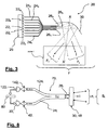
- This projector assembly comprises a plurality of light sources 22 a, 22 b, ..., 22 n. These light sources consist, for example, of polychromatic light emitting diodes, emitting a white light.
- the diodes 22 a, 22 b, ..., 22 n are controlled by an electronic control circuit 25.
- light-emitting diode arrays currently available as power diodes, comprising a plurality of diodes juxtaposed on the same substrate.
- Each diode 22 a, 22 b, ..., 22 n is associated with a light guide 24 a, 24 b, ..., 24 n, respectively, for example via an optical device so the majority of the light flux emitted by the diode is injected into a first end of the corresponding light guide.
- the second ends 26 a, 26 b, ..., 26 n of the guides 24 a, 24 b, ..., 24 n are combined so as to be side by side and aligned with each other.
- the whole of the second ends 26 a, 26 b, ..., 26 n is then placed at the focus of a reflecting mirror 30, of the type with complex surface, such as for example described in documents FR 2,760,067 and FR 2,760,068 , in the name of the plaintiff.
- the mirrors described in these documents intended to equip motor vehicle headlamps, have the particularity of distributing the light vertically (formation of the horizontal cut and that which forms an angle of 15 degrees) as well as horizontally (distribution of the light on the ground) ensuring a very good homogeneity.
- the protective glass of the projector is freed from any optical function, and is therefore smooth, or very weakly deviating.
- all the light sources 22 a, 22 b, ..., 22 n are turned on, all the ends 26 a, 26 b, ..., 26 n of the light guides 24 a, 24 b, ... 24n behaves like a continuous filament.
- the mirror 30 then forms a conventional illumination beam F.
- the beam F is actually composite, and it results from the superposition of the elementary light beams, each generated by one of the light sources 22 a, 22 b, ..., 22 n.
- the beam F i is generated in the direction i by the end 26 j of the guide 24 i , itself supplied with light by the light source 22 i
- the beam F j is generated in the direction j by the end 26 d of guide 24 d , which is itself powered by light from the light source 22 d .
- the partial beams F i , F j thus constitute a beam F, organized around an optical axis X-X '.
- the beam F then comprises all the elementary beams F a , F b , ..., F n , except the beam F i . It follows therefore that the light beam F illuminates the road scene in front of the vehicle, except in the direction i, corresponding to the elementary beam F i generated by the light source 22 i . Similarly, if the sources 22 i and 22 j are alone extinguished, the beam F then comprises all the elementary beams F a , F b , ..., F n , except the beams F i and F j .
- the light beam F illuminates the road scene in front of the vehicle, except in the directions i and j, corresponding to the elementary beams F i and F j generated by the light sources 22 j and 22 j .
- the beam F therefore has in the directions i and j shaded areas, such as the areas AV, AR and PS on the Figure 1 .
- the directions i and j will be such that the shadow areas are merged with the zones AR and PS of the Figure 1 , so as not to dazzle the driver of the vehicle V2 through its mirror, and not be dazzled by the retroreflection in the panel P.
- the headlamp 20 can for example illuminate the road above the horizontal cutoff to provide additional illumination to conventional crossing lighting that is to say in zone I of the Figure 1 .
- the direction i will be such that the shadow zone is confused with the AV zone of the Figure 1 , so as not to dazzle the driver of the vehicle V1.
- the directions i, j and k will be such that the shadow zones merge with the zones AV, AR and PS of the Figure 1 , so as not to dazzle the drivers of the vehicles V1 and V2, and not to be dazzled by the retroreflection in the panel P.
- the processing system 3 after having located an external light source such as V1, V2 or P on the Figure 1 , control the extinction of the sources 22 i , 22 j and / or 22 k to create the shadow areas AV, AR and / or PS of the Figure 1 to avoid dazzling the drivers of other vehicles and / or to avoid being dazzled by traffic signs.
- an external light source such as V1, V2 or P on the Figure 1
- This projector assembly generally designated by reference numeral 40, there further comprises a plurality of light sources 22 a, 22 b, ..., 22 n, which may also consist of light emitting diodes polychroma tick, emitting white light.
- the diodes 22 a, 22 b, ..., 22 n are as in the previous example controlled by an electronic drive circuit 25.
- the diodes 22 a, 22 b, ..., 22 n are again associated with light guides 24 a, 24 b, ..., 24 n, respectively.
- a light injector device 42 a , 42 b may be interposed between the diodes and the light guides. , ..., 42 n .
- An example of such a light injector device 42 i is shown in more detail on the Figure 5 .
- the device consists of a first collimator element 44 i , receiving all of the luminous flux emitted by the diode 22 i , and transforming all this light into a beam of parallel rays.
- This parallel beam is then received by a convergent element 46 i , which focuses all the light to its focus F i .
- a convergent element 46 i which focuses all the light to its focus F i .
- Such a light injector device can of course be used with the light guides of the embodiment of the invention.
- Figure 3 Such a light injector device can of course be used with the light guides of the embodiment of the invention.
- All of the second ends 26 a, 26 b, ..., 26 n of the guides 24 a, 24 b, ..., 24 n are combined so as to be side by side and aligned with each other .
- the whole of the second ends 26 a, 26 b, ..., 26 n is then placed at the focus of a convergent lens 48 plano-convex, the same type as those used to design elliptical lighting modules.
- a light source such as the filament of an incandescent lamp or the electric arc of a discharge lamp
- a mirror forms a real image of this source at its second focus, thus generating a spot of light concentration.
- a convergent lens is arranged so that its object focus coincides with the second focus of the elliptical mirror, so that this lens forms infinity an image of the spot of luminous concentration.
- This image at infinity then constitutes the light beam of illumination provided by the elliptical module, typically a driving beam.
- there is usually a cache in the object focal plane of the converging lens this cache intercepting the portion of the light rays that emerge from the converging lens being directed above the regulatory cutoff.
- the second ends 26 a, 26 b, ..., 26 n of the guides 24 a, 24 b, ..., 24 n constitute separate light sources, located at the same place as the concentration spot a modulus conventional elliptical lighting.
- the lens 48 forms images at infinity of these light sources 26 a , 26 b , ..., 26 n .
- the set of these infinite images then constitutes a lighting light beam F projected by the convergent plano-convex lens, and composed of the partial light beams F i , F j , the resulting beam F being again organized around an optical axis X-X '.
- the treatment system 3 after having located a direction in which it is undesirable to emit light rays, to control the extinction of one or more sources 22 i , 22 i and / or 22 k to create in the total light beam the shadow areas AV, AR and / or PS of the Figure 1 to avoid dazzling the drivers of other vehicles and / or to avoid being dazzled by traffic signs.
- This set projector generally designated by the reference 50, this time comprises a common light source 22.
- This common light source 22 consists of one or more separate sources, but whose light fluxes are all concentrated in one place.
- an elliptical module mirror as mentioned above, by disposing a discharge lamp at the first focus of a mirror substantially in the shape of an ellipsoid of revolution, and considering the concentration spot. formed at the second focus of the mirror as a common light source 22.
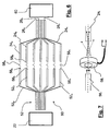
- the light coming from the common light source 22 is injected into a beam 52 of light guides, so that the first end of each individual guide 52 a, 52 b, ..., 52 n receives substantially the same amount of light.
- the light guides 52 a, 52 b, ..., 52 n in which light from the common source 22 was injected were then unbundled so that their second ends 56 a, 56 b, ..., 56 n serve as a light source for light guides 24 a, 24 b, ..., 24 n, as in the embodiments of Figures 3 and 4 , each guide 52 j being associated with a single guide 24 j .
- All of the second ends 26 a, 26 b, ..., 26 n of the guides 24 a, 24 b, ..., 24 n are combined so as to be side by side and aligned with each other at the focus of a lighting beam forming device 60.
- the device 60 may consist of a reflection system, similar to the mirror 30 in the Figure 3 , or a projection system, similar to the lens 48 of the Figure 4 , to emit a light beam F organized around an optical axis X-X '.
- modulation of the light penetrating into the guides 24 a , 24 b , ..., 24 n can be obtained by inserting a modulator shutter device 58 i between the output face of the guides 54 i and the input face of the guides 24. i .
- modulators 58 i have been schematically represented by switches.
- a shutter device 58 i may consist of a simple mechanical or electromechanical shutter, allowing the interposition of an opaque element in the path of the light rays between the guides 52 i and 24 i or the controlled deviation of the light rays between these two guides.
- piezoelectric polymers may be used.
- mechanically defocusable lenses such as those known under the trade name "Varioptic”, or else micro-mirrors whose orientation is electrically controlled. Holographic lenses, as well as electrically defocusable flat lenses currently under development, can also be used for this purpose.
- the device 58 i may also consist of a shutter or an optical modulator, for example an electrochromic glass interposed in the path of the light rays between the guides 52 i and 24 j or an electro-controllable liquid crystal system.
- a lens of this type comprises an enclosure filled with a first conductive liquid, such as water, a drop of a second liquid being placed at rest on an area of a first face of an insulating wall of the enclosure, the two liquids being immiscible, of different optical indices and neighboring densities.
- the first liquid is conductive
- the second liquid is insulating, for example oil, and means are used to apply an electrical voltage between the conductive liquid and an electrode disposed on the second side of the wall.
- the drop of oil has a variable profile, because it will wet differently the wall on which it was deposited, as well as the difference in surface tension between them.
- two liquids is modified by the application of the electric field, which has the effect of modifying the focal length of the lens itself composed of this drop.
- the focal length is adjusted by applying the appropriate voltage, so that the lens focuses the light received from the guide 56 i on the input face of the guide 24 i , which transmits the light of a guide to the other, or that it focuses this light away from the input face of the guide 24 i , as shown in dashed lines on the Figure 7 , which transmits very little light from one guide to another.
- the processing system 3 after having located in the images captured by the detection system 2 an external light source such as V1, V2 or P on the Figure 1 , control the extinction of the sources 22 i , 22 j and / or 22 k to create the shadow areas AV, AR and / or PS of the Figure 1 to avoid dazzling the drivers of other vehicles and / or to avoid being dazzled by traffic signs.
- an external light source such as V1, V2 or P on the Figure 1
- the partial light beams F i , F j have a small vertical numerical aperture, of the order of a few degrees, so as to optimize and refine the modulation of the illumination provided. by the resulting beam F.
- the numerical aperture of the partial beams F i , F j close to the optical axis XX ' is smaller than that of the partial beams F i , F j whose mean directions are farther from the optical axis X-X ', so as to increase the definition of the modulation of the light beam F in the vicinity of the optical axis XX' of the projector 20, 40 or 60.
- this optical axis X-X 'being parallel to the longitudinal axis of the vehicle is directed in a direction in which the information is most numerous for the driver of the vehicle: vehicles traveling in the same direction or in the opposite direction, characters and possible obstacles, and therefore need to be illuminated with modulated manner according to the invention with maximum selectivity.
- both the intensity and angular accuracy required are lower laterally than in the extension of the longitudinal axis of the vehicle.
- the light sources 26 i , 26 j are arranged in one or two superposed horizontal lines, so that the partial light beams F i , F j are joined.
- the total beam created by this line of light sources is close to that of a complementary low-altitude road beam, with the possibility of modulating different portions of this complementary beam, as has been seen above.
- the total beam created by this second line of light sources is generally less horizontally extended than the total beam created by the first line of light sources, and that the partial beams F k , F l created by the upper line are of greater horizontal extent. This minimizes the number of light sources in the second line, which significantly reduces the complexity of the system.
- the upper line of light sources makes it possible, in a beam complementary to a passing beam, to modulate in height the luminous intensity emitted to reduce the glare due to the signaling panels located at height on gantries, while allowing, on average distance, not to dazzle drivers of vehicles traveling in the opposite direction and above average height, such as trucks and some minivans, while illuminating the bottom of their vehicle, which remains visible.
- a complementary light beam to a passing beam modular as seen above, and which illuminates the areas of the road scene that are not illuminated by the regulatory passing beam, and which are likely to include an obstacle relevant for night driving or a potentially dazzling reflective object.
- the invention proposes constituting a regulatory lighting beam by the superposition of several elementary light beams, each of these beams being associated with an individual light source. So if we replace the light sources 22a, 22b, ..., 22 i of the first and second embodiments shown schematically in Figures 3 and 4
- light detectors 122 a, 122 b, ..., 122 n can be simply whether one or more light sources present in the road scene ahead of the vehicle, and in which regions of this scene they are located , depending on the light detector (s) 122 i providing an output signal.
- the detectors 122i may advantageously consist of photodiodes or phototransistors.
- the light emitted by the source 22 i is injected into a guide 24 i by means of an injector 42 i , the second end 26 i of this guide being at the focus of a beam forming system F i of illumination in the direction i such as a mirror 30 or a lens 48.
- the beam forming system 30 or 48 will form an image on the second end 26 i of the guide 24 i , applying the principle of reverse return of light.
- a separator 70 i on the guide 24 i , it will be possible to direct the light rays received from the external source S i in a guide 124 i so that these rays are finally received by a detector 122 i .
- the detector 122 i receives light, it means that an external light source S i is in the illumination beam F of the vehicle, and more particularly in the partial beam F i , and that it is therefore projectors or lights of another vehicle or a retro-reflective sign.
- the detector 122 i then sends a signal to an electronic element 80 j , which then controls the extinction of the source 22 i .
- the set of electronic elements 80 i can be combined in an electronic system 80 for processing the signals generated by all the detectors 122 i , the electronic system 80 can then be much simpler to produce, faster and more reliable than the processing system 3, as described in relation to the Figure 2 .
- the two detectors simultaneously provide a signal greater than a predetermined threshold, or if only the colorless filter detector provides a signal greater than a predetermined threshold, it means that the light received is white, and therefore comes from a vehicle traveling in the direction reverse. If only the detector with red filter provides a signal greater than a predetermined threshold, it means that the received light is red, and therefore comes from a vehicle traveling in the same direction.
- any light-emitting diode usually dedicated to the emission of a light beam, is also able to function as an optical detector in a spectral band close to its emission spectral range. .
- the white light emitting diodes whose flux is obtained, at least in part, by conversion using phosphors, are not very sensitive as light detectors in the visible spectrum (they have in practice only at high fluxes of ultraviolet rays). Nevertheless, today there exist miniature housings of comparable size to those of the above-mentioned diodes and having 2 to 4 emitter chips devoid of phosphorus, very close to each other. These diodes thus make it possible to create a white light beam by additive synthesis.
- Each light-emitting diode will then be driven by the electronic control circuit 25 so as to operate alternately in a transmission mode and in a reception mode.
- the time intervals during which the diodes operate in receive mode are chosen to be short enough so as not to disturb the lighting beam and be imperceptible to the driver's eyes.
- the rise and fall times of light-emitting diodes used in lighting and vehicle signaling are very low, and in any case much lower than the time constants of the human eye, such as retinal persistence, which are order of 25 Hertz, which allows switching operation with such short time intervals.
- the electronic control circuit 25 then controls for each light-emitting diode during a first time interval operation of the light-emitting diode for the formation of a partial light beam in the vehicle lighting beam, and during a second interval temporal operation of the diode in optical detection of external light source in the direction of the partial beam associated with the considered diode.
- the electronic control circuit 25 also comprises electronic detection circuits connected to each diode for receiving the measurement signal produced by the latter in response to the reception of a light beam emitted by an external source during the second time interval, in receiving mode, and outputting detection information resulting from a processing of the measurement signal.
- the electronic control circuit 25 also comprises for each diode switching circuits controlled during the second time interval, in reception mode, to inhibit the power supply of the light emitting diode during the first time interval, in transmission mode, in case of detecting the presence of an external light source during this second time interval of reception.
- the electronic control circuit 25 in such a way that a chip emitting in a length of determined wave, corresponding for example to the green color, emits a very brief pulse, of the order of a few milliseconds, and at low frequency, of the order of a few tens of Hertz, so as to be imperceptible by the eye human.
- the electronic control circuit 25 can then use in the time slot considered the chip emitting the complementary color of the first, for example the red color, as a detector. It is thus possible to produce an obstacle presence detector, even if it is not illuminated, in the angular sector and in the direction corresponding to those of the partial beam associated with this diode.
- a miniature housing comprising several radiation emitting chips of different wavelengths further has the advantage of being able to discriminate the nature of the received light, namely white or red, without the interposition of additional color filter.
- the diodes are sensitive to light rays of wavelength less than that of the light it emits.
- the simple analysis of the signals emitted by the diodes of the housing will make it possible to know the color of the light that they have received.
- the whole of a road lighting beam may consist of elementary light beams as described, so as to present to the driver an optimal illumination of the road scene. It may also be provided that the modulated lighting beam according to the invention is an additional beam to the passing beam, located above the cutoff of this beam dipped.
- the invention then provides a higher crossing illumination than usual lighting, located above the cut, while ensuring that this additional lighting does not dazzle the drivers of possible vehicles traveling on the same road, and does not dazzle the driver himself as a result of retroreflections on signs.
- This additional light obtained in zone I allows the driver to see the road scene beyond the cutoff C.
- the projector of the invention provides better perception and better visibility of the road to the driver. Indeed, this projector allows a classic lighting of the road scene and as well as more distant lighting, beyond the cut. Even if this lighting has dark or dark spots, even if they are numerous, for example in the case of heavy traffic, the driver necessarily has better visibility than with conventional lighting since this lighting more far away is additional lighting.
- the device can be used to draw the driver's attention to a potential obstacle, and illuminating this obstacle and not lighting up or less intensely its immediate vicinity.
- the device can be used to draw the driver's attention to a potential obstacle, and illuminating this obstacle and not lighting up or less intensely its immediate vicinity.
- several optical devices for example several mirrors such as in the Figure 3 or more lenses such as 48 in the Figure 4 , which together contribute to form a single beam, each mirror and / or lens being in turn associated with a group of light sources.
Landscapes
- Engineering & Computer Science (AREA)
- General Engineering & Computer Science (AREA)
- Physics & Mathematics (AREA)
- Microelectronics & Electronic Packaging (AREA)
- Optics & Photonics (AREA)
- Mechanical Engineering (AREA)
- General Physics & Mathematics (AREA)
- Multimedia (AREA)
- Theoretical Computer Science (AREA)
- Chemical & Material Sciences (AREA)
- Combustion & Propulsion (AREA)
- Transportation (AREA)
- Lighting Device Outwards From Vehicle And Optical Signal (AREA)
- Photo Coupler, Interrupter, Optical-To-Optical Conversion Devices (AREA)
Claims (13)
- Kraftfahrzeugscheinwerfer zur modulierten Beleuchtung einer Straßenszene, mit wenigstens einer Lichtquelle (26i, 26j), die einer Vorrichtung (30, 48) zur Bildung eines Beleuchtungslichtbündels zugeordnet ist,
der Art, dass er eine Vielzahl von Lichtquellen (26i, 26j, 56i, 56j) umfasst, die jeweils in Verbindung mit der Vorrichtung (30, 48) zur Bildung eines Beleuchtungslichtbündels ein Teillichtbündel (Fi, Fj) emittieren, wobei durch die Überlagerung der Teillichtbündel (Fi, Fj) ein Lichtbündel (F) gebildet wird, wobei jede Lichtquelle (26i, 26j) individuell modulierbar ist, um den Lichtstrom wenigstens eines in einer vorbestimmten Richtung (i, j) emittierten Teillichtbündels (Fi, Fj) in dem Beleuchtungslichtbündel derart zu steuern, dass die Lichtquelle wenigstens eines Teillichtbündels so gelöscht wird, dass das daraus resultierende Lichtbündel keine oder wenige Lichtstrahlen in einer vorbestimmten Richtung enthält, die Lichtquellen (26i, 26j) von zwei Enden (26i, 26j) von Lichtleitern (24i, 24j) gebildet sind, die das durch ihr erstes Ende empfangene Licht übertragen, die ersten Enden der Lichtleiter (24i, 24j) jeweils das Licht einer Lichtemissionsvorrichtung (22i, 22j) empfangen, dessen Intensität individuell gesteuert werden kann, die Lichtemissionsvorrichtungen (22i, 22j) von Leuchtdioden (22i 22j) gebildet sind, die weißes Licht emittieren, die Lichtemissionsvorrichtungen (22i, 22j) durch einen elektronischen Steuerkreis (25) gesteuert werden und die Leuchtdioden (22i, 22j) durch den elektronischen Steuerkreis (25) so gesteuert werden, dass sie alternativ in einem Emissionsmodus und in einem Empfangsmodus arbeiten. - Scheinwerfer nach Anspruch 1,
dadurch gekennzeichnet, dass die Vorrichtung (30) zur Bildung eines Beleuchtungslichtbündels von einem Spiegelreflektor (30) des Typs mit komplexer Oberfläche gebildet ist, in dessen Brennpunkt die Lichtquellen (26i, 26j) angeordnet sind. - Scheinwerfer nach Anspruch 1,
dadurch gekennzeichnet, dass die Vorrichtung (48) zur Bildung eines Beleuchtungslichtbündels von einer Sammellinse (48) gebildet ist, in deren Brennpunkt die Lichtquellen (26i, 26j) angeordnet sind. - Scheinwerfer nach Anspruch 1,
dadurch gekennzeichnet, dass die ersten Enden der Lichtleiter (24i, 24j) jeweils das Licht einer Lichtmodulationsvorrichtung (58i, 58j) empfangen, deren Transmissionsgrad individuell gesteuert werden kann. - Scheinwerfer nach Anspruch 4,
dadurch gekennzeichnet, dass die Lichtmodulationsvorrichtung (58i, 58j) durch eine mechanische oder elektromechanische Verschlussvorrichtung, durch piezoelektrische Polymere, durch mechanisch defokussierbare Linsen, durch Mikroreflektoren gebildet ist. - Scheinwerfer nach Anspruch 4,
dadurch gekennzeichnet, dass die Lichtmodulationsvorrichtung (58i, 58j) durch eine Verschlussvorrichtung oder einen optischen Modulator, ein elektrochromes Glas oder ein System mit elektrisch steuerbaren Flüssigkristallen gebildet ist. - Scheinwerfer nach Anspruch 4,
dadurch gekennzeichnet, dass die Lichtmodulationsvorrichtung (58i, 58j) durch eine Linse mit elektrisch veränderbarer Brennweite gebildet ist. - Scheinwerfer nach einem der Ansprüche 1 bis 7,
dadurch gekennzeichnet, dass die Lichtmodulationsvorrichtungen (58i, 58j) zwischen der Eintrittsfläche der Lichtleiter (24i, 24j) und der Austrittsseite von Primärlichtleitern (52i, 52j) eingefügt sind, deren Eintrittsflächen das gesamte Licht einer einzigen Lichtemissionsvorrichtung empfangen. - Scheinwerfer nach Anspruch 1,
dadurch gekennzeichnet, dass Lichteinkopplungsvorrichtungen (42i, 42j) zwischen den Leuchtdioden (22i, 22j) und den Eintrittsflächen der Lichtleiter (24i, 24j) eingefügt sind. - Scheinwerfer nach einem der Ansprüche 1 bis 9,
dadurch gekennzeichnet, dass er ferner ein System (2) zum Detektieren von externen Lichtquellen (V1, V2, P) in der Straßenszene vor dem Fahrzeug aufweist. - Scheinwerfer nach Anspruch 10,
dadurch gekennzeichnet, dass das Detektionssystem (2) durch eine Wärmebildkamera, eine Infrarotkamera oder eine CCD- oder CMOS-Videokamera gebildet ist. - Scheinwerfer nach Anspruch 10,
dadurch gekennzeichnet, dass das Detektionssystem (2) durch Photodioden (122i, 122j), Phototransistoren (122i, 122j) oder als Empfangsdioden verwendete Leuchtdioden (22i, 22j) gebildet ist. - Scheinwerfer nach einem der Ansprüche 1 bis 12,
dadurch gekennzeichnet, dass die Lichtquellen (26i, 26j, 56i, 56j) entlang einer horizontalen Linie oder entlang zweier übereinanderliegender horizontaler Linien angeordnet sind, wobei das Beleuchtungslichtbündel (F) ein zu einem Abblendlichtbündel komplementäres Lichtbündel ist.
Applications Claiming Priority (1)
| Application Number | Priority Date | Filing Date | Title |
|---|---|---|---|
| FR0510893A FR2894905B1 (fr) | 2005-10-25 | 2005-10-25 | Procede d'eclairage module d'une route et projecteur de vehicule mettant en oeuvre ce procede. |
Publications (2)
| Publication Number | Publication Date |
|---|---|
| EP1780462A1 EP1780462A1 (de) | 2007-05-02 |
| EP1780462B1 true EP1780462B1 (de) | 2009-12-30 |
Family
ID=36645320
Family Applications (1)
| Application Number | Title | Priority Date | Filing Date |
|---|---|---|---|
| EP06291634A Ceased EP1780462B1 (de) | 2005-10-25 | 2006-10-20 | Moduliertes Fahrzeugsbeleuchtungsverfahren und dieses Verfahren umsetzender Scheinwerfer |
Country Status (5)
| Country | Link |
|---|---|
| EP (1) | EP1780462B1 (de) |
| JP (1) | JP2007182214A (de) |
| AT (1) | ATE453833T1 (de) |
| DE (1) | DE602006011406D1 (de) |
| FR (1) | FR2894905B1 (de) |
Cited By (1)
| Publication number | Priority date | Publication date | Assignee | Title |
|---|---|---|---|---|
| EP2551579B2 (de) † | 2011-07-25 | 2018-10-10 | Sharp Kabushiki Kaisha | Lichtquellenvorrichtung, Beleuchtungsvorrichtung, Fahrzeugscheinwerfer und Fahrzeug |
Families Citing this family (44)
| Publication number | Priority date | Publication date | Assignee | Title |
|---|---|---|---|---|
| JP4624257B2 (ja) * | 2005-12-28 | 2011-02-02 | 株式会社小糸製作所 | 車両用灯具 |
| DE102007036081A1 (de) * | 2007-08-01 | 2009-02-05 | GM Global Technology Operations, Inc., Detroit | Beleuchtungseinrichtung für ein Kraftfahrzeug und Verfahren zur Steuerung einer Leuchte |
| DE102007040042B4 (de) | 2007-08-24 | 2019-02-21 | HELLA GmbH & Co. KGaA | System zum Erzeugen eines Lichtbündels im Vorfeld eines Kraftfahrzeuges |
| DE102007052746A1 (de) * | 2007-11-06 | 2009-05-07 | Hella Kgaa Hueck & Co. | Scheinwerfer für Fahrzeuge |
| DE102007052745A1 (de) * | 2007-11-06 | 2009-05-07 | Hella Kgaa Hueck & Co. | Scheinwerfer für Fahrzeuge |
| DE102007054048A1 (de) * | 2007-11-13 | 2009-05-14 | Daimler Ag | Verfahren und Vorrichtung für eine Fahrlichtsteuerung eines Fahrzeugs |
| FR2923890A1 (fr) | 2007-11-16 | 2009-05-22 | Valeo Vision Sa | Dispositif d'eclairage pour vehicule automobile |
| JP5151452B2 (ja) * | 2007-12-19 | 2013-02-27 | 株式会社豊田中央研究所 | 情報表示装置 |
| JP4995748B2 (ja) * | 2008-01-29 | 2012-08-08 | 株式会社小糸製作所 | 車両用前照灯装置及び車両用前照灯装置の制御方法 |
| JP4613970B2 (ja) | 2008-03-12 | 2011-01-19 | トヨタ自動車株式会社 | 車両用照明装置 |
| DE102008025947A1 (de) | 2008-05-30 | 2009-12-03 | Hella Kgaa Hueck & Co. | Verfahren und Vorrichtung zum Steuern der Lichtabgabe eines Frontscheinwerfers eines Fahrzeugs |
| DE102008053945B4 (de) * | 2008-10-30 | 2018-12-27 | Volkswagen Ag | Verfahren zum Steuern einer Scheinwerferanordnung für ein Fahrzeug und Scheinwerferanordnung hierfür |
| DE102009021018A1 (de) * | 2009-05-13 | 2010-11-18 | Dr. Ing. H.C. F. Porsche Aktiengesellschaft | Verfahren zum Betreiben eines Fahrzeugscheinwerfers |
| JP5438410B2 (ja) * | 2009-07-15 | 2014-03-12 | 株式会社小糸製作所 | 車両用前照灯装置 |
| FR2948439B1 (fr) | 2009-07-21 | 2011-08-05 | Valeo Vision | Module d'eclairage pour projecteur de vehicule automobile, et projecteur equipe d'au moins un tel module. |
| DE102009053581B3 (de) * | 2009-10-05 | 2011-03-03 | Automotive Lighting Reutlingen Gmbh | Lichtmodul für eine Beleuchtungseinrichtung eines Kraftfahrzeugs |
| DE102009054227B4 (de) | 2009-11-21 | 2025-10-02 | Volkswagen Ag | Verfahren zum Steuern einer Scheinwerferanordnung für ein Fahrzeug und Scheinwerferanordnung |
| JP5394901B2 (ja) * | 2009-11-25 | 2014-01-22 | 株式会社小糸製作所 | 車両用前照灯システム |
| EP2338731B1 (de) * | 2009-12-04 | 2014-09-03 | Hella KGaA Hueck & Co. | Steuergerät zur Steuerung von Fahrzeugscheinwerfern zum Erzeugen einer Lichtverteilung mit nachführbaren vertikalen Hell-Dunkel-Grenzen |
| JP2011162008A (ja) * | 2010-02-08 | 2011-08-25 | Mitsubishi Electric Corp | ヘッドランプ用led点灯装置 |
| DE102010015731A1 (de) * | 2010-04-21 | 2011-10-27 | Audi Ag | Verfahren zur Steuerung eines Scheinwerfersystems eines Kraftfahrzeugs und Kraftfahrzeug |
| DE102011004937A1 (de) | 2011-03-02 | 2012-09-06 | Robert Bosch Gmbh | Verfahren und Steuergerät zum Beeinflussen einer Beleuchtungsszene vor einem Fahrzeug |
| DE102013009791A1 (de) * | 2013-06-12 | 2014-12-18 | Audi Ag | Leuchtvorrichtung für ein Kraftfahrzeug und Verfahren zum Betreiben |
| DE102013213649A1 (de) * | 2013-07-12 | 2015-01-15 | Bayerische Motoren Werke Aktiengesellschaft | Verfahren zur Bildverarbeitung in einem Kraftfahrzeug |
| KR20150052638A (ko) * | 2013-11-06 | 2015-05-14 | 현대모비스 주식회사 | Adb 헤드램프 시스템 및 adb 헤드램프 시스템을 이용한 빔 제어 방법 |
| JP6669428B2 (ja) * | 2014-08-13 | 2020-03-18 | 株式会社小糸製作所 | 照明装置と照明方法及び表示システム |
| DE102014019344A1 (de) * | 2014-12-22 | 2016-06-23 | GM Global Technology Operations LLC (n. d. Ges. d. Staates Delaware) | Kraftfahrzeugscheinwerfer, Kraftfahrzeugscheinwerfersystem, Kraftfahrzeug sowie Verfahren zum Betrieb eines Kraftfahrzeugs |
| US9896022B1 (en) * | 2015-04-20 | 2018-02-20 | Ambarella, Inc. | Automatic beam-shaping using an on-car camera system |
| DE102015008729A1 (de) * | 2015-07-07 | 2017-01-12 | GM Global Technology Operations LLC (n. d. Ges. d. Staates Delaware) | Kraftfahrzeugscheinwerferanordnung, Kraftfahrzeugscheinwerfersystem, Kraftfahrzeug sowie Verfahren zum Betrieb eines Kraftfahrzeugs |
| FR3048392B1 (fr) * | 2016-03-02 | 2019-04-05 | Valeo Vision | Projecteur anti-eblouissement |
| DE102016005458B4 (de) * | 2016-07-29 | 2026-04-02 | Mercedes-Benz Group AG | Betreiben eines Scheinwerfers |
| FR3055267B1 (fr) * | 2016-08-31 | 2021-04-16 | Valeo Schalter & Sensoren Gmbh | Dispositif de commande d'un projecteur de lumiere d'un vehicule, dispositif d'eclairage et procede associes |
| CN108162858B (zh) * | 2016-12-07 | 2020-05-29 | 杭州海康威视数字技术股份有限公司 | 车载监控装置及其方法 |
| DE102017209815A1 (de) * | 2017-06-09 | 2018-12-13 | Osram Gmbh | Beleuchtungsvorrichtung für einen scheinwerfer eines fahrzeugs, scheinwerfer, lichtsystem, fahrzeug sowie verfahren |
| AT519976B1 (de) * | 2017-07-05 | 2018-12-15 | Zkw Group Gmbh | Verfahren zum melden einer von gegenverkehr ausgehenden blendung und eine kraftfahrzeugbeleuchtungseinrichtung zum ausführen eines solchen verfahrens |
| DE102017214407A1 (de) * | 2017-08-18 | 2019-02-21 | Osram Gmbh | Beleuchtungssystem und scheinwerfer |
| FR3119009A1 (fr) * | 2021-01-21 | 2022-07-22 | Psa Automobiles Sa | Procédé de commande d’un projecteur de véhicule automobile |
| CN117120300A (zh) * | 2021-04-16 | 2023-11-24 | 株式会社小糸制作所 | 车辆用灯具系统、配光控制装置以及配光控制方法 |
| CN221969464U (zh) * | 2021-09-07 | 2024-11-08 | 华域视觉科技(上海)有限公司 | 前照灯和包括该前照灯的车辆 |
| CA3232012A1 (en) * | 2021-09-17 | 2023-03-23 | Joshua Grabovic | Adaptive driving light system |
| CN116963337A (zh) * | 2022-04-13 | 2023-10-27 | 华域视觉科技(上海)有限公司 | 前照灯、车辆及前照灯的控制方法 |
| CN115146014A (zh) * | 2022-06-20 | 2022-10-04 | 岚图汽车科技有限公司 | 一种高精度地图的阳光炫目场景集成方法及系统 |
| CN116400325B (zh) * | 2022-09-14 | 2024-01-26 | 苏州睿新微系统技术有限公司 | 一种光发射组件及激光雷达 |
| DE102024114380A1 (de) * | 2024-05-23 | 2025-11-27 | HELLA GmbH & Co. KGaA | Scheinwerfer für Fahrzeuge sowie Ansteuerverfahren |
Family Cites Families (13)
| Publication number | Priority date | Publication date | Assignee | Title |
|---|---|---|---|---|
| IT1237274B (it) * | 1989-11-17 | 1993-05-27 | Carello Spa | Gruppo di illuminazione per veicoli, in particolare autoveicoli |
| FR2671163B1 (fr) * | 1990-12-27 | 1993-04-30 | Valeo Vision | Projecteur de vehicule automobile a moyens de conduction de lumiere. |
| JPH1040713A (ja) * | 1996-07-23 | 1998-02-13 | Fuji Heavy Ind Ltd | 車両のヘッドランプ装置 |
| US6144158A (en) * | 1996-11-07 | 2000-11-07 | Sensci Corporation | Adaptive/anti-blinding headlights |
| ES2255737T3 (es) * | 1997-12-09 | 2006-07-01 | Federal-Mogul Ignition Company | Estructuras de guia de ondas para iluminacion de vehiculo. |
| DE19901413C2 (de) * | 1999-01-16 | 2002-12-05 | Helmut Haf | Elektronik eines Fahrzeuges, vorzugsweise eines Kraftfahrzeuges |
| US6281806B1 (en) * | 2000-10-12 | 2001-08-28 | Ford Global Technologies, Inc. | Driver road hazard warning and illumination system |
| DE10242864A1 (de) * | 2002-09-14 | 2004-03-25 | Adam Opel Ag | Automatische Scheinwerfer-Regeleinrichtung für ein Kraftfahrzeug mit mindestens einem mindestens eine Lichtquelle aufweisenden Scheinwerfer |
| GB0225839D0 (en) * | 2002-11-06 | 2002-12-11 | Ford Global Tech Inc | Interactive lighting system |
| DE10314524A1 (de) * | 2003-03-31 | 2004-10-28 | Osram Opto Semiconductors Gmbh | Scheinwerfer und Scheinwerferelement |
| DE10321564A1 (de) * | 2003-05-14 | 2004-12-16 | Audi Ag | Kraftfahrzeugscheinwerfer |
| US20040263346A1 (en) * | 2003-06-27 | 2004-12-30 | Guide Corporation, A Delaware Corporation | Solid state adaptive forward lighting system |
| DE10344173A1 (de) * | 2003-09-22 | 2005-04-28 | Hella Kgaa Hueck & Co | Scheinwerfer für Fahrzeuge |
-
2005
- 2005-10-25 FR FR0510893A patent/FR2894905B1/fr not_active Expired - Fee Related
-
2006
- 2006-10-20 DE DE602006011406T patent/DE602006011406D1/de active Active
- 2006-10-20 AT AT06291634T patent/ATE453833T1/de not_active IP Right Cessation
- 2006-10-20 EP EP06291634A patent/EP1780462B1/de not_active Ceased
- 2006-10-25 JP JP2006289309A patent/JP2007182214A/ja active Pending
Cited By (1)
| Publication number | Priority date | Publication date | Assignee | Title |
|---|---|---|---|---|
| EP2551579B2 (de) † | 2011-07-25 | 2018-10-10 | Sharp Kabushiki Kaisha | Lichtquellenvorrichtung, Beleuchtungsvorrichtung, Fahrzeugscheinwerfer und Fahrzeug |
Also Published As
| Publication number | Publication date |
|---|---|
| FR2894905B1 (fr) | 2009-07-10 |
| JP2007182214A (ja) | 2007-07-19 |
| FR2894905A1 (fr) | 2007-06-22 |
| DE602006011406D1 (de) | 2010-02-11 |
| ATE453833T1 (de) | 2010-01-15 |
| EP1780462A1 (de) | 2007-05-02 |
Similar Documents
| Publication | Publication Date | Title |
|---|---|---|
| EP1780462A1 (de) | Moduliertes Fahrzeugsbeleuchtungsverfahren und dieses Verfahren umsetzender Scheinwerfer | |
| EP2690352B1 (de) | Adaptives Beleuchtungssystem für Kraftfahrzeug | |
| EP1442927B1 (de) | Verfahren und Scheinwerfer zur modulierten Beleuchtung einer Strasse | |
| US7015944B2 (en) | Device for improving visibility in vehicles | |
| EP1369639B1 (de) | Kfz-Scheinwerfer nach dem Projektionsprinzip mit einer sekundären Lichtquelle | |
| EP3002504B1 (de) | Leuchtmodul zur beleuchtung für kraftfahrzeug | |
| FR3027654B1 (fr) | Systeme d'eclairage et/ou de signalisation comprenant des moyens de telemetrie | |
| EP3093557B1 (de) | Beleuchtungsmodul mit doppelfunktion für abblend- und fernlicht für kraftfahrzeug | |
| FR2934669A1 (fr) | Installation d'eclairage de vehicule automobile | |
| FR2704625A1 (fr) | Installation de projecteurs pour véhicules automobiles. | |
| EP2415636A2 (de) | Beleuchtungssystem für Kraftfahrzeug | |
| JP2021101436A (ja) | ヘッドライト装置 | |
| EP3027961A1 (de) | Projektor und beleuchtungssystem, insbesondere für ein kraftfahrzeug | |
| FR2977927A1 (fr) | Dispositif d'eclairage/signalisation multifonctions pour vehicule automobile. | |
| FR2730035A1 (fr) | Projecteur infrarouge pour systeme d'aide a la vision pour vehicule automobile et systeme d'aide a la vision le comportant | |
| EP3350507B1 (de) | Beleuchtungsvorrichtung für kraftfahrzeuge | |
| JP2016146583A (ja) | 撮像装置、移動体機器制御システム及びプログラム | |
| FR2916036A1 (fr) | Projecteur de vehicule | |
| JP2016200528A (ja) | 物体検出装置、移動体機器制御システム及び物体検出用プログラム | |
| FR3019266A1 (fr) | Systeme d'eclairage pour vehicule avec reglage automatise | |
| JP6701542B2 (ja) | 検出装置、移動体機器制御システム及び検出用プログラム | |
| FR3056695A1 (fr) | Dispositif d'eclairage pour vehicule automobile comportant un guide de lumiere | |
| FR3053758A1 (fr) | Dispositif d'eclairage et/ou de signalisation pour vehicule automobile | |
| FR2699259A1 (fr) | Projecteur de véhicule automobile comportant des moyens pour engendrer deux faisceaux différents à partir d'une même source et d'un même miroir. | |
| EP3276249B1 (de) | Leuchtsystem für beleuchtungsvorrichtung und optional für signalvorrichtung für kraftfahrzeug |
Legal Events
| Date | Code | Title | Description |
|---|---|---|---|
| PUAI | Public reference made under article 153(3) epc to a published international application that has entered the european phase |
Free format text: ORIGINAL CODE: 0009012 |
|
| AK | Designated contracting states |
Kind code of ref document: A1 Designated state(s): AT BE BG CH CY CZ DE DK EE ES FI FR GB GR HU IE IS IT LI LT LU LV MC NL PL PT RO SE SI SK TR |
|
| AX | Request for extension of the european patent |
Extension state: AL BA HR MK YU |
|
| 17P | Request for examination filed |
Effective date: 20071010 |
|
| 17Q | First examination report despatched |
Effective date: 20071107 |
|
| AKX | Designation fees paid |
Designated state(s): AT BE BG CH CY CZ DE DK EE ES FI FR GB GR HU IE IS IT LI LT LU LV MC NL PL PT RO SE SI SK TR |
|
| GRAP | Despatch of communication of intention to grant a patent |
Free format text: ORIGINAL CODE: EPIDOSNIGR1 |
|
| GRAS | Grant fee paid |
Free format text: ORIGINAL CODE: EPIDOSNIGR3 |
|
| GRAA | (expected) grant |
Free format text: ORIGINAL CODE: 0009210 |
|
| AK | Designated contracting states |
Kind code of ref document: B1 Designated state(s): AT BE BG CH CY CZ DE DK EE ES FI FR GB GR HU IE IS IT LI LT LU LV MC NL PL PT RO SE SI SK TR |
|
| REG | Reference to a national code |
Ref country code: GB Ref legal event code: FG4D Free format text: NOT ENGLISH |
|
| REG | Reference to a national code |
Ref country code: CH Ref legal event code: EP |
|
| REG | Reference to a national code |
Ref country code: IE Ref legal event code: FG4D |
|
| REF | Corresponds to: |
Ref document number: 602006011406 Country of ref document: DE Date of ref document: 20100211 Kind code of ref document: P |
|
| PG25 | Lapsed in a contracting state [announced via postgrant information from national office to epo] |
Ref country code: SE Free format text: LAPSE BECAUSE OF FAILURE TO SUBMIT A TRANSLATION OF THE DESCRIPTION OR TO PAY THE FEE WITHIN THE PRESCRIBED TIME-LIMIT Effective date: 20091230 Ref country code: FI Free format text: LAPSE BECAUSE OF FAILURE TO SUBMIT A TRANSLATION OF THE DESCRIPTION OR TO PAY THE FEE WITHIN THE PRESCRIBED TIME-LIMIT Effective date: 20091230 Ref country code: LT Free format text: LAPSE BECAUSE OF FAILURE TO SUBMIT A TRANSLATION OF THE DESCRIPTION OR TO PAY THE FEE WITHIN THE PRESCRIBED TIME-LIMIT Effective date: 20091230 |
|
| REG | Reference to a national code |
Ref country code: NL Ref legal event code: VDEP Effective date: 20091230 |
|
| LTIE | Lt: invalidation of european patent or patent extension |
Effective date: 20091230 |
|
| PG25 | Lapsed in a contracting state [announced via postgrant information from national office to epo] |
Ref country code: LV Free format text: LAPSE BECAUSE OF FAILURE TO SUBMIT A TRANSLATION OF THE DESCRIPTION OR TO PAY THE FEE WITHIN THE PRESCRIBED TIME-LIMIT Effective date: 20091230 Ref country code: PL Free format text: LAPSE BECAUSE OF FAILURE TO SUBMIT A TRANSLATION OF THE DESCRIPTION OR TO PAY THE FEE WITHIN THE PRESCRIBED TIME-LIMIT Effective date: 20091230 Ref country code: SI Free format text: LAPSE BECAUSE OF FAILURE TO SUBMIT A TRANSLATION OF THE DESCRIPTION OR TO PAY THE FEE WITHIN THE PRESCRIBED TIME-LIMIT Effective date: 20091230 |
|
| PG25 | Lapsed in a contracting state [announced via postgrant information from national office to epo] |
Ref country code: AT Free format text: LAPSE BECAUSE OF FAILURE TO SUBMIT A TRANSLATION OF THE DESCRIPTION OR TO PAY THE FEE WITHIN THE PRESCRIBED TIME-LIMIT Effective date: 20091230 |
|
| REG | Reference to a national code |
Ref country code: IE Ref legal event code: FD4D |
|
| PG25 | Lapsed in a contracting state [announced via postgrant information from national office to epo] |
Ref country code: RO Free format text: LAPSE BECAUSE OF FAILURE TO SUBMIT A TRANSLATION OF THE DESCRIPTION OR TO PAY THE FEE WITHIN THE PRESCRIBED TIME-LIMIT Effective date: 20091230 Ref country code: NL Free format text: LAPSE BECAUSE OF FAILURE TO SUBMIT A TRANSLATION OF THE DESCRIPTION OR TO PAY THE FEE WITHIN THE PRESCRIBED TIME-LIMIT Effective date: 20091230 Ref country code: EE Free format text: LAPSE BECAUSE OF FAILURE TO SUBMIT A TRANSLATION OF THE DESCRIPTION OR TO PAY THE FEE WITHIN THE PRESCRIBED TIME-LIMIT Effective date: 20091230 Ref country code: ES Free format text: LAPSE BECAUSE OF FAILURE TO SUBMIT A TRANSLATION OF THE DESCRIPTION OR TO PAY THE FEE WITHIN THE PRESCRIBED TIME-LIMIT Effective date: 20100410 Ref country code: IS Free format text: LAPSE BECAUSE OF FAILURE TO SUBMIT A TRANSLATION OF THE DESCRIPTION OR TO PAY THE FEE WITHIN THE PRESCRIBED TIME-LIMIT Effective date: 20100430 Ref country code: PT Free format text: LAPSE BECAUSE OF FAILURE TO SUBMIT A TRANSLATION OF THE DESCRIPTION OR TO PAY THE FEE WITHIN THE PRESCRIBED TIME-LIMIT Effective date: 20100430 Ref country code: BG Free format text: LAPSE BECAUSE OF FAILURE TO SUBMIT A TRANSLATION OF THE DESCRIPTION OR TO PAY THE FEE WITHIN THE PRESCRIBED TIME-LIMIT Effective date: 20100330 |
|
| PG25 | Lapsed in a contracting state [announced via postgrant information from national office to epo] |
Ref country code: SK Free format text: LAPSE BECAUSE OF FAILURE TO SUBMIT A TRANSLATION OF THE DESCRIPTION OR TO PAY THE FEE WITHIN THE PRESCRIBED TIME-LIMIT Effective date: 20091230 Ref country code: CZ Free format text: LAPSE BECAUSE OF FAILURE TO SUBMIT A TRANSLATION OF THE DESCRIPTION OR TO PAY THE FEE WITHIN THE PRESCRIBED TIME-LIMIT Effective date: 20091230 |
|
| PG25 | Lapsed in a contracting state [announced via postgrant information from national office to epo] |
Ref country code: IE Free format text: LAPSE BECAUSE OF FAILURE TO SUBMIT A TRANSLATION OF THE DESCRIPTION OR TO PAY THE FEE WITHIN THE PRESCRIBED TIME-LIMIT Effective date: 20091230 Ref country code: CY Free format text: LAPSE BECAUSE OF FAILURE TO SUBMIT A TRANSLATION OF THE DESCRIPTION OR TO PAY THE FEE WITHIN THE PRESCRIBED TIME-LIMIT Effective date: 20091230 Ref country code: GR Free format text: LAPSE BECAUSE OF FAILURE TO SUBMIT A TRANSLATION OF THE DESCRIPTION OR TO PAY THE FEE WITHIN THE PRESCRIBED TIME-LIMIT Effective date: 20100331 |
|
| PLBE | No opposition filed within time limit |
Free format text: ORIGINAL CODE: 0009261 |
|
| STAA | Information on the status of an ep patent application or granted ep patent |
Free format text: STATUS: NO OPPOSITION FILED WITHIN TIME LIMIT |
|
| 26N | No opposition filed |
Effective date: 20101001 |
|
| PG25 | Lapsed in a contracting state [announced via postgrant information from national office to epo] |
Ref country code: DK Free format text: LAPSE BECAUSE OF FAILURE TO SUBMIT A TRANSLATION OF THE DESCRIPTION OR TO PAY THE FEE WITHIN THE PRESCRIBED TIME-LIMIT Effective date: 20091230 |
|
| PG25 | Lapsed in a contracting state [announced via postgrant information from national office to epo] |
Ref country code: IT Free format text: LAPSE BECAUSE OF FAILURE TO SUBMIT A TRANSLATION OF THE DESCRIPTION OR TO PAY THE FEE WITHIN THE PRESCRIBED TIME-LIMIT Effective date: 20091230 |
|
| BERE | Be: lapsed |
Owner name: VALEO VISION Effective date: 20101031 |
|
| PG25 | Lapsed in a contracting state [announced via postgrant information from national office to epo] |
Ref country code: MC Free format text: LAPSE BECAUSE OF NON-PAYMENT OF DUE FEES Effective date: 20101031 |
|
| REG | Reference to a national code |
Ref country code: CH Ref legal event code: PL |
|
| GBPC | Gb: european patent ceased through non-payment of renewal fee |
Effective date: 20101020 |
|
| PG25 | Lapsed in a contracting state [announced via postgrant information from national office to epo] |
Ref country code: LI Free format text: LAPSE BECAUSE OF NON-PAYMENT OF DUE FEES Effective date: 20101031 Ref country code: CH Free format text: LAPSE BECAUSE OF NON-PAYMENT OF DUE FEES Effective date: 20101031 |
|
| PG25 | Lapsed in a contracting state [announced via postgrant information from national office to epo] |
Ref country code: BE Free format text: LAPSE BECAUSE OF NON-PAYMENT OF DUE FEES Effective date: 20101031 Ref country code: GB Free format text: LAPSE BECAUSE OF NON-PAYMENT OF DUE FEES Effective date: 20101020 |
|
| PG25 | Lapsed in a contracting state [announced via postgrant information from national office to epo] |
Ref country code: HU Free format text: LAPSE BECAUSE OF FAILURE TO SUBMIT A TRANSLATION OF THE DESCRIPTION OR TO PAY THE FEE WITHIN THE PRESCRIBED TIME-LIMIT Effective date: 20100701 Ref country code: LU Free format text: LAPSE BECAUSE OF NON-PAYMENT OF DUE FEES Effective date: 20101020 |
|
| PG25 | Lapsed in a contracting state [announced via postgrant information from national office to epo] |
Ref country code: TR Free format text: LAPSE BECAUSE OF FAILURE TO SUBMIT A TRANSLATION OF THE DESCRIPTION OR TO PAY THE FEE WITHIN THE PRESCRIBED TIME-LIMIT Effective date: 20091230 |
|
| REG | Reference to a national code |
Ref country code: FR Ref legal event code: PLFP Year of fee payment: 10 |
|
| REG | Reference to a national code |
Ref country code: FR Ref legal event code: PLFP Year of fee payment: 11 |
|
| REG | Reference to a national code |
Ref country code: FR Ref legal event code: PLFP Year of fee payment: 12 |
|
| REG | Reference to a national code |
Ref country code: DE Ref legal event code: R079 Ref document number: 602006011406 Country of ref document: DE Free format text: PREVIOUS MAIN CLASS: F21S0008120000 Ipc: F21S0041000000 |
|
| REG | Reference to a national code |
Ref country code: FR Ref legal event code: PLFP Year of fee payment: 13 |
|
| PGFP | Annual fee paid to national office [announced via postgrant information from national office to epo] |
Ref country code: FR Payment date: 20221020 Year of fee payment: 17 |
|
| PGFP | Annual fee paid to national office [announced via postgrant information from national office to epo] |
Ref country code: DE Payment date: 20221012 Year of fee payment: 17 |
|
| P01 | Opt-out of the competence of the unified patent court (upc) registered |
Effective date: 20230528 |
|
| REG | Reference to a national code |
Ref country code: DE Ref legal event code: R119 Ref document number: 602006011406 Country of ref document: DE |
|
| PG25 | Lapsed in a contracting state [announced via postgrant information from national office to epo] |
Ref country code: FR Free format text: LAPSE BECAUSE OF NON-PAYMENT OF DUE FEES Effective date: 20231031 Ref country code: DE Free format text: LAPSE BECAUSE OF NON-PAYMENT OF DUE FEES Effective date: 20240501 |