EP1780506A2 - Gyroscope à fibre optique interférométrique utilisant une technique de modulation pour calibrer la référence de longueur d'onde en temps réel dans un environnement sévère - Google Patents
Gyroscope à fibre optique interférométrique utilisant une technique de modulation pour calibrer la référence de longueur d'onde en temps réel dans un environnement sévère Download PDFInfo
- Publication number
- EP1780506A2 EP1780506A2 EP06123307A EP06123307A EP1780506A2 EP 1780506 A2 EP1780506 A2 EP 1780506A2 EP 06123307 A EP06123307 A EP 06123307A EP 06123307 A EP06123307 A EP 06123307A EP 1780506 A2 EP1780506 A2 EP 1780506A2
- Authority
- EP
- European Patent Office
- Prior art keywords
- ifog
- port
- wavelength
- coupler
- signal
- Prior art date
- Legal status (The legal status is an assumption and is not a legal conclusion. Google has not performed a legal analysis and makes no representation as to the accuracy of the status listed.)
- Withdrawn
Links
Images



Classifications
-
- G—PHYSICS
- G01—MEASURING; TESTING
- G01C—MEASURING DISTANCES, LEVELS OR BEARINGS; SURVEYING; NAVIGATION; GYROSCOPIC INSTRUMENTS; PHOTOGRAMMETRY OR VIDEOGRAMMETRY
- G01C19/00—Gyroscopes; Turn-sensitive devices using vibrating masses; Turn-sensitive devices without moving masses; Measuring angular rate using gyroscopic effects
- G01C19/58—Turn-sensitive devices without moving masses
- G01C19/64—Gyrometers using the Sagnac effect, i.e. rotation-induced shifts between counter-rotating electromagnetic beams
- G01C19/72—Gyrometers using the Sagnac effect, i.e. rotation-induced shifts between counter-rotating electromagnetic beams with counter-rotating light beams in a passive ring, e.g. fibre laser gyrometers
- G01C19/726—Phase nulling gyrometers, i.e. compensating the Sagnac phase shift in a closed loop system
Definitions
- the present invention relates generally to interferometric fiber optic gyroscopes (IFOGs) and improvements thereto.
- IFOGs interferometric fiber optic gyroscopes
- Figure 1 illustrates the basic operation and fundamental components of an IFOG.
- the IFOG design comprises six major components: fiber light source 110, coupler 112, multi-function integrated optic chip (IOC) 114 containing Y-junction and phase modulators, fiber sensing coil 118, photo detectors 120 and processing electronics 125.
- Fiber light source 110 generates light, and sends the light to the fiber sensing loop 118 through source coupler 112 and IOC 114.
- the source coupler 112 takes the input light and splits it in half to send it through both output legs.
- One output leg takes the source light further to IOC 114.
- the other output leg can be terminated without any further usage or used to detect the light intensity and excess noise for further processing.
- the source coupler 112 works in reverse with light sent to photo detector 120 for rate signal processing.
- the IOC 114 has multiple functions implemented in a single chip as is well-known in the art, including Y-junction, polarizer, and phase modulators.
- the polarizer which may be the waveguide itself such as a proton-exchange waveguide, polarizes the incoming light to accommodate not only single-polarization modulation, but also suppression of bias instability induced by the cross-couplings between the two polarization modes.. Without the polarizer the un-modulated light forms additional interference which reduces the contrast of the sensing interferometer.
- the Y-junction in the IOC splits the light into the sensing coil 118 for clockwise (CW) and counter clockwise (CCW) waves, This junction also combines the CW and CCW waves returning from the sensing loop 118 and sends the light back through the source coupler 112 and the photo detector 120.
- the phase modulator is used to modulate the light to create higher sensitivity with rate polarity in the interferogram.
- the modulator also provides the closed loop phase to cancel the Sagnac phase shift in closed loop operation.
- Figures 2A and 2B illustrate a resulting interferogram, which is basically a raised cosine function corresponding to the interference pattern of the CW and CCW waves. Without the injected modulation, there is no sensitivity near zero due to constructive interference. At ⁇ (180°) phase difference, the interferogram shows destructive interference resulting in zero light intensity at the photo detector level.
- a square wave shown towards the bottom of Figure 2A is usually applied to the phase modulator to bias the interferogram away from the zero point to the phase of ⁇ /2 for rate detection sensitivity, linearity, and polarity.
- Figure 2B depicts the case when there is a Sagnac phase shift from the fiber sensing coil.
- the photo detector signal is demodulated in the IFOG processor 125 through subtraction of level B from level A to obtain the actual rotation rate.
- the rotation rate output is a function of the non-linearity of the interferogram. Fluctuation of the light intensity along the optical path including light source 110, coupler 112, IOC 114, coil 118, and multiple fiber splices also impact the rotation rate measurement accuracy. Open loop IFOG operation therefore requires significant compensation techniques to obtain reasonable bias stability and scale factor linearity performance.
- closed loop operation In order to eliminate the dependency on the light intensity amplitude, another modulation technique called closed loop operation is now more commonly employed in IFOGs.
- the IFOG processor demodulates the photo detector signal and sends a feedback signal to the phase modulator to nullify the Sagnac phase shift.
- the closed loop operation forces the gyro to operate at the null condition.
- the digital representation of the voltage level necessary for locking at the null condition is continuously updated and stored in a register, such as an accumulator, inside the IFOG processing circuitry to indicate the magnitude of the feedback signal required to cancel the demodulation signal from photo detector.
- the rotation rate does not depend on the nos-linearity of the interferogram nor on the intensity fluctuation along the optical path.
- the closed loop design provides better modulation performance by eliminating power dependency and shifting the one to one scale factor nonlinearity to a square-root reduction due to imperfection in IOC and its associated drives.
- the high speed modulation required by the closed loop signal design makes the phase modulator the key component to high performance.
- WDM wave division multiplexor
- the present invention introduces a unique and novel signal processing technique in IFOG loop-closure operations to temporarily suppress the gyro returned signal and at the same time extract radiation-induced (or any environmental-induced) wavelength drift, in real time, for reference WDM (scale factor) and dual-photodetector calibration.
- the suppression of the IFOG returned signal can be relatively short in terms of loop transit time or multiples of loop transit time.
- a key advantage of this processing technique is that it can be implemented electronically. And, no additional optical components such as modulators are needed.
- the gyro return signal Periodically, at a preset interval, the gyro return signal is shut off by biasing the gyro at ⁇ or multiples of ⁇ . During this short shut off period, there is no gyro return signal. Consequently, the WDM error plus the mismatch between the two photodetectors can be calibrated with the external absolute wavelength reference.
- the wavelength calibration can be open-loop through measuring the power difference of the two photodetectors pigtailed to the WDM output leads.
- the technique is implemented in IFOG loop-closure circuitry embodied in a field programmable gate array (FPGA), or in an application specific integrated circuit (ASIC).
- the gyro bias is controlled by sending the proper modulation depth other than ⁇ (such as ⁇ /2 or 3 ⁇ /4) to the phase modulator of the IOC.
- the gyro signal is on for most of the time, and off periodically for extracting the scale factor calibration information to be processed by the FPGA (or ASIC) for scale factor error calibration.
- the scale factor calibration is performed as follows.
- a WDM When a WDM is fabricated as a scale factor reference device, it means that the 50/50 output splitting ratio of the WDM is tuned to the mean wavelength of the IFOG FLS with a certain tolerance.
- power output at the two output ports is equal and balanced.
- the power difference between the two output WDM ports is zero because there is no mean wavelength drift in the input port.
- Such a power difference at the two output ports versus mean wavelength drift at the input port is a linear relationship over a wide range.
- the WDM is preferably recalibrated based on an absolute wavelength reference as shown in Figure 7.
- the absolute wavelength reference has a spectral line very close to the mean wavelength of FLS (also the mean wavelength of the 50/50 WDM coupler) employed in the IFOG.
- the gyro returned signal is shut off by modulating at ⁇ , power from the absolute wavelength reference is then launched into the WDM coupler for recalibration based on the same principle described above.
- recalibration process not only calibrate the the mean wavelength drift, but includes the responsivity mismatch between the two photodetectors, and can be AC modulated for better signal-to-noise ratio.
- the recalibration mean wavelength (scale factor) value is stored in the memory for further processing or sensor scale factor calibration.
- Figure 1 illustrates the basic operation and fundamental components of an IFOG.
- Figures 2A and 2B illustrate a typical interferogram generated by an IFOG.
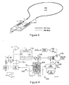
- Figure 3 depicts a dual depolarizer IFOG design.
- Figure 4 depicts an exemplary functional diagram of an IFOG.
- Figures 5 and 6 illustrate successively improved performance characteristics of the IFOG of Figure 4.
- Figure 7 illustrates an exemplary embodiment of the present invention.
- the very first fiber optic gyroscopes were constructed using single mode (SM) fiber.
- SM single mode
- PM fiber Polarization maintaining (PM) fiber, which appeared on the market in the early 1980s, offered properties which preserved the simplicity of the gyroscope architecture and at the same time offered a simple solution to the problems of signal fading and polarization errors, Therefore, the most prevalent design thus far has used PM fiber to meet the stringent performance requirements of navigation gyroscopes,
- Dual Depolarizer Design In fiber optic gyros which use SM fiber, light is depolarized before entering the gyro loop. Depolarization is accomplished by bunching linearly polarized light, emerging from the IOC, into the sections of polarization maintaining fibers at 45°, as shown in Figure 3. Since light propagates with different velocities in the two eigen states of linearly birefringent PM fiber, there is a delay between the eigen modes (often called the fast and the slow propagation mode). The birefringence induced delays t 1 and t 2 in two depolarizers are substantially longer than the coherence time of the light source, t c .
- the light in the fast mode is decorrelated with the light in the slow mode resulting in "random" polarization state at the end of the depolarizer.
- the gyro architecture shown in Figure 3 which utilizes two depolarizers located on the opposite sides of the loop, provides increased immunity to several non-reciprocal effects, and thus establishes the preferred architecture for low drift applications. It is noted that SM fiber could also be used.
- a high-performance depolarized gyro design utilizes a dual depolarizer gyro architecture like that illustrated in Figure 3.
- An exemplary function diagram of such an IFOG is shown in Figure 4.
- Light from the fiber light source (FLS) 110 propagates through a 50/50 coupler (or a circulator) 112 to the integrated optics chip (IOC) 114 where the light wave is split into clockwise and counter-clockwise waves. Rotation introduces a phase shift, j S , between these two waves.
- WDM wave division multiplexor
- the WDM 410 splits the incoming wave again. However, this time, the splitting ratio reflects the mean wavelength of the arriving light wave.
- Dual detectors at the WDM 410 provide information about the total power, P C + P T , and power difference between the two ports of the WDM 410, P C - P T .
- the respective signals are used to close two servo loops: rotation sensing loop 420 and mean wavelength control loop 430, as shown in Figure 4.
- the total power, P C + P T , when processed by dosed loop electronics 440 provides information about the non-reciprocal, rotation-induced Sagnac phase shift, j S , between the counter propagating waves.
- the loop is closed by the phase modulation which injects into the gyro loop the phase shift equal in magnitude but opposite in sign to j S .
- the power difference, P C - P T provides a measure of the mean wavelength and it is used to close the mean wavelength servo loop 430 by changing the operating condition of the fiber light source 110.
- the wavelength servo can be replaced by wavelength calibration in which power difference of the WDM coupler is fed to the loop-closure electronics for digitization, processing and gyro scale factor calibration, all done by firmware control and processing (see Figure 7).
- the components shown in the block diagram of Figure 4 (and Figure 7) are in temperature stabilized environment.
- the scale factor is directly proportional to the mean wavelength and to the size of the sensing coil both of which can be affected by environmental perturbation, especially radiation.
- the approach according to embodiments of the present invention is to maximize the mean wavelength stability of the light arriving to the WDM and further improve the stability by employing WDM based active wavelength control or calibration. Preferably, close attention is also paid to the design of the sensing coil and its mechanical stability.
- FLS stability Typically, the spectrum of a fiber light source (FLS) can be decomposed into a sum of three gaussian functions. The analysis of the spectra before and after radiation clearly indicates that not all of the gaussian peaks comprising the spectrum are affected by the radiation, to the same degree.
- the emission peak which is most stable (in wavelength and power) is the peak at 1.53mm.
- An FLS with power contained primarily in the 1.53mm emission peak is known. See, for example, U.S. Patent 6,744,966 , which is incorporated herein by reference.
- This passive spectral shaping design results in substantial reduction of the radiation induced mean wavelength shift from 2100ppm (without spectral shaping), to about 13ppm (with spectral shaping).
- Active wavelength control using the gyro detected signal is especially desirable because radiation can affect not only the FLS but also the transmission properties of the fiber used in the sensing coil, which also leads to the shift of the mean wavelength. Additional information about active wavelength control can also be found in U.S. Patents 5,323,409 and 5,684,590 , which are incorporated herein by reference.
- the present invention includes an Absolute Wavelength Reference 700, as shown in Figure 7, that is connected to one of the input ports of WDM 410.
- This absolute wavelength reference 700 could be, for example, an atomic reference or other reference device that will not change with time or external perturbation.
- the IFOG operating cycle is split into measurement and calibration periods. More specifically, the IFOG measures the input rotation rate most of the time by operating at other than +/- ⁇ (preferably at either 1/2 ⁇ or 3/4 ⁇ for better random noise). And, depending on the application and/or environmental dynamics, for a fraction of the duty cycle (e.g., from 0.01% to 10%), the IFOG operates at ⁇ to shut down the gyro returning signal (light) and let only the signal from the Absolute Wavelength Reference 700 reach the system detector to calibrate the IFOG scale factor.
- a fraction of the duty cycle e.g., from 0.01% to 10%
- the specification may have presented the method and/or process of the present invention as a particular sequence of steps. However, to the extent that the method or process does not rely on the particular order of steps set forth herein, the method or process should not be limited to the particular sequence of steps described. As one of ordinary skill in the art would appreciate, other sequences of steps may be possible. Therefore, the particular order of the steps set forth in the specification should not be construed as limitations on the claims, In addition, the claims directed to the method and/or process of the present invention should not be limited to the performance of their steps in the order written, and one skilled in the art can readily appreciate that the sequences may be varied and still remain within the spirit and scope of the present invention.
Landscapes
- Engineering & Computer Science (AREA)
- Physics & Mathematics (AREA)
- Power Engineering (AREA)
- Optics & Photonics (AREA)
- Electromagnetism (AREA)
- General Physics & Mathematics (AREA)
- Radar, Positioning & Navigation (AREA)
- Remote Sensing (AREA)
- Gyroscopes (AREA)
Applications Claiming Priority (1)
| Application Number | Priority Date | Filing Date | Title |
|---|---|---|---|
| US11/262,911 US20070097374A1 (en) | 2005-11-01 | 2005-11-01 | IFOG modulation technique for real-time calibration of wavelength reference under harsh environment |
Publications (2)
| Publication Number | Publication Date |
|---|---|
| EP1780506A2 true EP1780506A2 (fr) | 2007-05-02 |
| EP1780506A3 EP1780506A3 (fr) | 2008-09-03 |
Family
ID=37714499
Family Applications (1)
| Application Number | Title | Priority Date | Filing Date |
|---|---|---|---|
| EP06123307A Withdrawn EP1780506A3 (fr) | 2005-11-01 | 2006-11-01 | Gyroscope à fibre optique interférométrique utilisant une technique de modulation pour calibrer la référence de longueur d'onde en temps réel dans un environnement sévère |
Country Status (3)
| Country | Link |
|---|---|
| US (1) | US20070097374A1 (fr) |
| EP (1) | EP1780506A3 (fr) |
| JP (1) | JP2007127648A (fr) |
Cited By (6)
| Publication number | Priority date | Publication date | Assignee | Title |
|---|---|---|---|---|
| CN101886925A (zh) * | 2010-05-27 | 2010-11-17 | 北京大学 | 基于载波调制的多波长干涉式光纤陀螺 |
| CN101943581A (zh) * | 2010-08-19 | 2011-01-12 | 中国航空工业第六一八研究所 | 陀螺力矩器线圈成型模具及成型方法 |
| CN103438881A (zh) * | 2013-08-20 | 2013-12-11 | 重庆华渝电气仪表总厂 | 一种抑制光纤环中间段背向散射噪声的方法 |
| CN104613954A (zh) * | 2015-01-27 | 2015-05-13 | 浙江大学 | 单光源双波峰的光纤陀螺仪 |
| US10830589B2 (en) | 2016-07-29 | 2020-11-10 | The Board Of Trustees Of Western Michigan University | Magnetic nanoparticle-based gyroscopic sensor |
| CN115574801A (zh) * | 2022-12-09 | 2023-01-06 | 中国船舶集团有限公司第七〇七研究所 | 一种基于波分频分复用的降低噪声的方法及光纤陀螺 |
Families Citing this family (18)
| Publication number | Priority date | Publication date | Assignee | Title |
|---|---|---|---|---|
| CA2531177A1 (fr) * | 2005-12-30 | 2007-06-30 | Jesse Zheng | Gyroscope de sagnac differentiel a onde entretenue modulee en frequence a fibre birefringente |
| US7515271B2 (en) * | 2006-04-03 | 2009-04-07 | Honeywell International Inc. | Wavelength calibration in a fiber optic gyroscope |
| US7777889B2 (en) * | 2008-08-07 | 2010-08-17 | Honeywell International Inc. | Bias-instability reduction in fiber optic gyroscopes |
| US7973938B2 (en) * | 2008-09-24 | 2011-07-05 | Honeywell International Inc. | Bias-reduced fiber optic gyroscope with polarizing fibers |
| US8446589B2 (en) * | 2009-03-06 | 2013-05-21 | Honeywell International Inc. | Residual intensity modulation (RIM) control loop in a resonator fiber-optic gyroscope (RFOG) |
| US8294900B2 (en) | 2009-04-01 | 2012-10-23 | Honeywell International Inc. | Systems and methods for resonator fiber optic gyroscope intensity modulation control |
| US8223341B2 (en) * | 2010-05-28 | 2012-07-17 | Honeywell International Inc. | System and method for enhancing signal-to-noise ratio of a resonator fiber optic gyroscope |
| US8213019B2 (en) | 2010-09-07 | 2012-07-03 | Honeywell International Inc. | RFOG with optical heterodyning for optical signal discrimination |
| US8773665B1 (en) | 2011-04-01 | 2014-07-08 | Emcore Corporation | Compact fiber optic gyroscope |
| US8798405B2 (en) * | 2011-08-04 | 2014-08-05 | Emcore Corporation | Method of making a fiber optic gyroscope |
| US8947671B2 (en) | 2013-02-22 | 2015-02-03 | Honeywell International Inc. | Method and system for detecting optical ring resonator resonance frequencies and free spectral range to reduce the number of lasers in a resonator fiber optic gyroscope |
| US9008221B2 (en) | 2013-04-01 | 2015-04-14 | Honeywell International Inc. | Spurious frequency attenuation servo |
| US9001336B1 (en) | 2013-10-07 | 2015-04-07 | Honeywell International Inc. | Methods and apparatus of tracking/locking resonator free spectral range and its application in resonator fiber optic gyroscope |
| US9041934B2 (en) | 2013-10-25 | 2015-05-26 | Honeywell International Inc. | Dispersion managed interferometric fiber optic gyroscope |
| CN106030318B (zh) | 2013-12-20 | 2020-11-17 | Abb电网瑞士股份公司 | 光纤传感器和方法 |
| US9429426B2 (en) | 2014-01-22 | 2016-08-30 | Northrop Grumman Systems Corporation | Adaptive inertial measurement system and method |
| US10502585B2 (en) | 2014-10-23 | 2019-12-10 | The Boeing Company | Gyro rate computation for an interferometric fiber optic gyro |
| US10914587B1 (en) | 2019-07-23 | 2021-02-09 | Honeywell International Inc. | Systems and methods for correcting errors in gyroscopes |
Family Cites Families (6)
| Publication number | Priority date | Publication date | Assignee | Title |
|---|---|---|---|---|
| US5184195A (en) * | 1991-05-28 | 1993-02-02 | Litton Systems, Inc. | Triaxial fiber optic Sagnac interferometer with single source and detector |
| US5598489A (en) * | 1994-07-27 | 1997-01-28 | Litton Systems, Inc. | Depolarized fiber optic rotation sensor with low faraday effect drift |
| US5684590A (en) * | 1995-12-29 | 1997-11-04 | Honeywell Inc. | Fiber optic gyroscope source wavelength control |
| US6801319B2 (en) * | 2002-01-03 | 2004-10-05 | Honeywell International, Inc. | Symmetrical depolarized fiber optic gyroscope |
| US7269190B2 (en) * | 2002-10-02 | 2007-09-11 | The Board Of Trustees Of The Leland Stanford Junior University | Er-doped superfluorescent fiber source with enhanced mean wavelength stability |
| US7227644B2 (en) * | 2004-02-26 | 2007-06-05 | Honeywell International, Inc. | Fiber optic gyroscope using a narrowband FBG filter as a wavelength reference |
-
2005
- 2005-11-01 US US11/262,911 patent/US20070097374A1/en not_active Abandoned
-
2006
- 2006-11-01 EP EP06123307A patent/EP1780506A3/fr not_active Withdrawn
- 2006-11-01 JP JP2006297852A patent/JP2007127648A/ja not_active Withdrawn
Cited By (9)
| Publication number | Priority date | Publication date | Assignee | Title |
|---|---|---|---|---|
| CN101886925A (zh) * | 2010-05-27 | 2010-11-17 | 北京大学 | 基于载波调制的多波长干涉式光纤陀螺 |
| CN101943581A (zh) * | 2010-08-19 | 2011-01-12 | 中国航空工业第六一八研究所 | 陀螺力矩器线圈成型模具及成型方法 |
| CN103438881A (zh) * | 2013-08-20 | 2013-12-11 | 重庆华渝电气仪表总厂 | 一种抑制光纤环中间段背向散射噪声的方法 |
| CN103438881B (zh) * | 2013-08-20 | 2016-01-20 | 重庆华渝电气仪表总厂 | 一种抑制光纤环中间段背向散射噪声的方法 |
| CN104613954A (zh) * | 2015-01-27 | 2015-05-13 | 浙江大学 | 单光源双波峰的光纤陀螺仪 |
| CN104613954B (zh) * | 2015-01-27 | 2017-04-12 | 浙江大学 | 单光源双波峰的光纤陀螺仪 |
| US10830589B2 (en) | 2016-07-29 | 2020-11-10 | The Board Of Trustees Of Western Michigan University | Magnetic nanoparticle-based gyroscopic sensor |
| CN115574801A (zh) * | 2022-12-09 | 2023-01-06 | 中国船舶集团有限公司第七〇七研究所 | 一种基于波分频分复用的降低噪声的方法及光纤陀螺 |
| CN115574801B (zh) * | 2022-12-09 | 2023-02-24 | 中国船舶集团有限公司第七〇七研究所 | 一种基于波分频分复用的降低噪声的方法及光纤陀螺 |
Also Published As
| Publication number | Publication date |
|---|---|
| EP1780506A3 (fr) | 2008-09-03 |
| JP2007127648A (ja) | 2007-05-24 |
| US20070097374A1 (en) | 2007-05-03 |
Similar Documents
| Publication | Publication Date | Title |
|---|---|---|
| EP1780506A2 (fr) | Gyroscope à fibre optique interférométrique utilisant une technique de modulation pour calibrer la référence de longueur d'onde en temps réel dans un environnement sévère | |
| Strandjord et al. | Resonator fiber optic gyro employing a polarization-rotating resonator | |
| Lefevre et al. | Integrated optics: a practical solution for the fiber-optic gyroscope | |
| US5090810A (en) | Ring resonator gyroscope controlling two servo control loops based on the output of a single interference detector | |
| JPS6129715A (ja) | 閉ル−プ干渉計において生じる非可逆的位相シフトを測定するための装置 | |
| JP5362180B2 (ja) | 光ファイバ・ジャイロスコープの非同期復調 | |
| EP3370076B1 (fr) | Système et procédé pour un magnétomètre à cavité faisant appel à un détecteur pound-drever-hall | |
| US5349441A (en) | Fiber optic gyroscope refractive index induced error compensation | |
| WO1996041132A1 (fr) | Suiveur de frequence propre pour bobine de detection en fibre optique | |
| CN112113556B (zh) | 一种基于自注入锁频的高灵敏度谐振式微光学陀螺及其检测方法 | |
| US9291458B2 (en) | Fiber-optic measurement device, gyrometer, and navigation and inertial-stabilization system | |
| US11378401B2 (en) | Polarization-maintaining fully-reciprocal bi-directional optical carrier microwave resonance system and angular velocity measurement method thereof | |
| US20030169428A1 (en) | Saw tooth bias modulation and loop closure for an interferometric fiber optic gyroscope | |
| Strandjord et al. | Effects of imperfect serrodyne phase modulation in resonator fiber optic gyroscopes | |
| RU2160885C1 (ru) | Способ стабилизации масштабного коэффициента волоконно-оптического гироскопа | |
| CN106796125A (zh) | 具有微分调制相位检测的干涉测定传感器 | |
| US5365337A (en) | Method and apparatus for compensating for the residual birefringence in interferometric fiber-optic gyros | |
| Strandjord et al. | Performance improvements of a polarization-rotating resonator fiber optic gyroscope | |
| RU2532997C2 (ru) | Стабилизированный твердотельный лазерный гироскоп | |
| CN114459457B (zh) | 基于互易调制二次解调的谐振式光纤陀螺系统及方法 | |
| Hu et al. | Compact resonant fiber-optic gyroscope with a broadband light source | |
| Carrara | Drift caused by phase-modulator nonlinearities in fiber gyroscopes | |
| Shu et al. | Zero-bias-suppressed angular velocity sensing via a dual-frequency optoelectronic oscillator | |
| Wang et al. | IFOG Output Fluctuation Caused by Electrostriction Effect and Its Solution | |
| Ferrar | Progress in fiber optic gyro development |
Legal Events
| Date | Code | Title | Description |
|---|---|---|---|
| PUAI | Public reference made under article 153(3) epc to a published international application that has entered the european phase |
Free format text: ORIGINAL CODE: 0009012 |
|
| AK | Designated contracting states |
Kind code of ref document: A2 Designated state(s): AT BE BG CH CY CZ DE DK EE ES FI FR GB GR HU IE IS IT LI LT LU LV MC NL PL PT RO SE SI SK TR |
|
| AX | Request for extension of the european patent |
Extension state: AL BA HR MK YU |
|
| PUAL | Search report despatched |
Free format text: ORIGINAL CODE: 0009013 |
|
| AK | Designated contracting states |
Kind code of ref document: A3 Designated state(s): AT BE BG CH CY CZ DE DK EE ES FI FR GB GR HU IE IS IT LI LT LU LV MC NL PL PT RO SE SI SK TR |
|
| AX | Request for extension of the european patent |
Extension state: AL BA HR MK RS |
|
| AKX | Designation fees paid | ||
| REG | Reference to a national code |
Ref country code: DE Ref legal event code: 8566 |
|
| STAA | Information on the status of an ep patent application or granted ep patent |
Free format text: STATUS: THE APPLICATION IS DEEMED TO BE WITHDRAWN |
|
| 18D | Application deemed to be withdrawn |
Effective date: 20090304 |