EP1780992A2 - Dispositif de communication avec deux boîtiers pour désactiver une touche en fonction du mouvement relatif des boîtiers - Google Patents
Dispositif de communication avec deux boîtiers pour désactiver une touche en fonction du mouvement relatif des boîtiers Download PDFInfo
- Publication number
- EP1780992A2 EP1780992A2 EP06022410A EP06022410A EP1780992A2 EP 1780992 A2 EP1780992 A2 EP 1780992A2 EP 06022410 A EP06022410 A EP 06022410A EP 06022410 A EP06022410 A EP 06022410A EP 1780992 A2 EP1780992 A2 EP 1780992A2
- Authority
- EP
- European Patent Office
- Prior art keywords
- housing
- communication terminal
- stepped surface
- main body
- control unit
- Prior art date
- Legal status (The legal status is an assumption and is not a legal conclusion. Google has not performed a legal analysis and makes no representation as to the accuracy of the status listed.)
- Granted
Links
- 238000004891 communication Methods 0.000 title claims abstract description 78
- 238000000034 method Methods 0.000 description 5
- 230000008901 benefit Effects 0.000 description 4
- 238000010586 diagram Methods 0.000 description 4
- 239000004973 liquid crystal related substance Substances 0.000 description 2
- 238000012986 modification Methods 0.000 description 2
- 230000004048 modification Effects 0.000 description 2
- 239000012141 concentrate Substances 0.000 description 1
- 230000003247 decreasing effect Effects 0.000 description 1
- 238000005516 engineering process Methods 0.000 description 1
Images





Classifications
-
- H—ELECTRICITY
- H04—ELECTRIC COMMUNICATION TECHNIQUE
- H04M—TELEPHONIC COMMUNICATION
- H04M1/00—Substation equipment, e.g. for use by subscribers
- H04M1/02—Constructional features of telephone sets
- H04M1/0202—Portable telephone sets, e.g. cordless phones, mobile phones or bar type handsets
- H04M1/0206—Portable telephones comprising a plurality of mechanically joined movable body parts, e.g. hinged housings
- H04M1/0241—Portable telephones comprising a plurality of mechanically joined movable body parts, e.g. hinged housings using relative motion of the body parts to change the operational status of the telephone set, e.g. switching on/off, answering incoming call
- H04M1/0245—Portable telephones comprising a plurality of mechanically joined movable body parts, e.g. hinged housings using relative motion of the body parts to change the operational status of the telephone set, e.g. switching on/off, answering incoming call using open/close detection
-
- H—ELECTRICITY
- H04—ELECTRIC COMMUNICATION TECHNIQUE
- H04M—TELEPHONIC COMMUNICATION
- H04M1/00—Substation equipment, e.g. for use by subscribers
- H04M1/66—Substation equipment, e.g. for use by subscribers with means for preventing unauthorised or fraudulent calling
- H04M1/667—Preventing unauthorised calls from a telephone set
- H04M1/67—Preventing unauthorised calls from a telephone set by electronic means
-
- H—ELECTRICITY
- H04—ELECTRIC COMMUNICATION TECHNIQUE
- H04M—TELEPHONIC COMMUNICATION
- H04M1/00—Substation equipment, e.g. for use by subscribers
- H04M1/02—Constructional features of telephone sets
- H04M1/0202—Portable telephone sets, e.g. cordless phones, mobile phones or bar type handsets
- H04M1/0206—Portable telephones comprising a plurality of mechanically joined movable body parts, e.g. hinged housings
- H04M1/0208—Portable telephones comprising a plurality of mechanically joined movable body parts, e.g. hinged housings characterized by the relative motions of the body parts
- H04M1/0225—Rotatable telephones, i.e. the body parts pivoting to an open position around an axis perpendicular to the plane they define in closed position
- H04M1/0233—Including a rotatable display body part
-
- H—ELECTRICITY
- H04—ELECTRIC COMMUNICATION TECHNIQUE
- H04M—TELEPHONIC COMMUNICATION
- H04M1/00—Substation equipment, e.g. for use by subscribers
- H04M1/02—Constructional features of telephone sets
- H04M1/0202—Portable telephone sets, e.g. cordless phones, mobile phones or bar type handsets
- H04M1/0206—Portable telephones comprising a plurality of mechanically joined movable body parts, e.g. hinged housings
- H04M1/0208—Portable telephones comprising a plurality of mechanically joined movable body parts, e.g. hinged housings characterized by the relative motions of the body parts
- H04M1/0235—Slidable or telescopic telephones, i.e. with a relative translation movement of the body parts; Telephones using a combination of translation and other relative motions of the body parts
-
- H—ELECTRICITY
- H04—ELECTRIC COMMUNICATION TECHNIQUE
- H04M—TELEPHONIC COMMUNICATION
- H04M1/00—Substation equipment, e.g. for use by subscribers
- H04M1/02—Constructional features of telephone sets
- H04M1/23—Construction or mounting of dials or of equivalent devices; Means for facilitating the use thereof
-
- H—ELECTRICITY
- H04—ELECTRIC COMMUNICATION TECHNIQUE
- H04M—TELEPHONIC COMMUNICATION
- H04M2250/00—Details of telephonic subscriber devices
- H04M2250/18—Details of telephonic subscriber devices including more than one keyboard unit
Definitions
- the present invention relates to a communication terminal.
- various design communication terminals e.g., a bar type terminal, a flip type terminal and a folder type terminal.
- FIG. 1 is an exploded perspective view showing a structure of a conventional folder type communication terminal.
- a folder type communication terminal comprises a main body 1 and a folder 2.
- the main body 1 and the folder 2 are hingedly coupled to each other.
- the folder 2 is hingedly rotated into an open position or a closed position with respect to the main body 1.
- the main body 1 includes an upper cover 6 which is formed with a plurality of holes 7 for keys 4, a lower cover 8 which is disposed under the upper cover 6 and coupled thereto, a circuit board 9 on which various components are mounted and which is interposed between the upper cover 6 and the lower cover 8, and a key pad (not shown) which is interposed between the upper cover 6 and the circuit board 9 for data input.
- the keys 4 on the key pad are inserted into the holes 7 of the upper cover 6, respectively, and exposed outside.
- the folder 2 includes a display device 3 (e.g., an LCD (Liquid Crystal Display)) for displaying an image corresponding to data, and a folder housing 5 for protecting the display device 3.
- a display device 3 e.g., an LCD (Liquid Crystal Display)
- a folder housing 5 for protecting the display device 3.
- the data input is performed by hingedly rotating the folder 2 into the open position from the main body 1 and pressing the keys 4.
- the slide type terminal is widely used until the commencement of a digital broadcasting service through communication terminals.
- the current trend is to develop the various swing type terminals.
- the types of the communication terminals developed until now include the bar type, flip type, folder type, slide type and swing type terminals.
- the flip type, folder type, slide type and swing type terminals commonly have a main body, and a movable unit which is connected structurally and electrically to the main body and can move freely to a predetermined extent with respect to the main body.
- the communication service is diversified more and more and continuously upgraded, it is very difficult to make the communication terminal compact.
- the arrangement of the keys is a very important design factor. Also, decreasing the number or size of the keys causes an inconvenience to users.
- the present invention is directed to a communication terminal that substantially obviates one or more problems due to limitations and disadvantages of the
- An object of the present invention is to provide a communication terminal which has an adequate structure for keys so as to sufficiently fulfill various communication services, to thereby make the communication terminal compact.
- Another object of the present invention is to provide a communication terminal which can control operation of the keys so as to minimize a data input error of the keys.
- a communication terminal comprises: a first housing; a second housing which is oppositely coupled to the first housing; and a control unit which interrupts operation of a data input part provided at either the first housing or the second housing according to movement of the second housing with respect to the first housing.
- the second housing may swing while opposing a portion of the first housing.
- the control unit may interrupt the operation of the data input part until the second housing swings to a predetermined angle.
- control unit may interrupt the operation of the data input part during a predetermined time from when the movement of the second housing is detected.
- the data input part includes at least one key.
- a communication terminal comprises: a main body housing which is formed with an upper stepped surface and a lower stepped surface; a first input part which is provided at a slanted surface formed between the upper stepped surface and the lower stepped surface; and an upper housing which swings while opposing the lower stepped surface of the main body housing.
- the communication terminal further comprises: a control unit which determines whether the upper housing swings or not and controls input operation of the first input part. If determining that the upper housing swings, the control unit disables the input operation of the first input part.
- control unit may disable the input operation of the first input part during a predetermined time from when the swinging of the upper housing is detected.
- control unit may disable the input operation of the first input part until the upper housing swings to a predetermined angle.
- the communication terminal further comprises: a second input part which is provided at the upper stepped surface of the main body housing.
- the communication terminal further comprises: a third input part which is provided at the lower stepped surface of the main body housing.
- the third input part may be shielded or exposed according to the swinging of the upper housing.
- the first input part includes at least one key.
- the upper housing includes at least one output part which is positioned at an opposite surface of the upper housing to a surface facing the lower stepped surface of the main body housing.
- the output part includes a display device.
- a communication terminal comprises: a main body which includes an upper stepped surface, a lower stepped surface and a slanted surface formed between the upper stepped surface and the lower stepped surface, the slanted surface being provided with at least one key; a display unit which is coupled to the lower stepped surface of the main body, the display unit swinging while opposing the lower stepped surface; and a control unit which determines whether the display unit swings or not and controls operation of the key. If determining that the display unit swings, the control unit temporarily interrupts the operation of the key.
- the upper stepped surface and the lower stepped surface of the main body are provided with keys. Accordingly, if determining that the display unit swings, the control unit temporarily interrupts the operation of at least one of the keys provided at the upper stepped surface and the lower stepped surface. Especially, the keys provided at the lower stepped surface are shielded or exposed according to the swinging of the display unit.
- the keys provided at the lower stepped surface and the keys provided at the slanted surface are formed at one key pad.
- FIG. 1 is an exploded perspective view showing a structure of a conventional folder type communication terminal
- FIG. 2 is a front view showing an operating state of an upper housing of a swing type terminal
- FIG. 3 is a block diagram showing an inner structure of a communication terminal in accordance with the present invention.
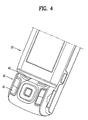
- FIG. 4 is a perspective view showing a closed state of an upper housing of a communication terminal in accordance with the present invention.
- FIG. 5 is a perspective view showing an open state of an upper housing of a communication terminal in accordance with the present invention.
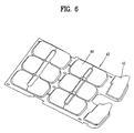
- FIG. 6 is a perspective view showing a key pad of a communication terminal in accordance with the present invention.
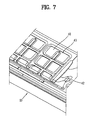
- FIG. 7 is a sectional view showing a key pad of a communication terminal in accordance with the present invention.
- FIG. 8 is a flow chart illustrating a data input control process of a communication terminal in accordance with the present invention.
- FIG. 9 is a timing diagram illustrating interrupt of a data input part of a communication terminal in accordance with the present invention.
- a communication terminal includes a main body, and a movable unit which is connected structurally and electrically to the main body and can move freely to a predetermined extent with respect to the main body.
- main body housing Components inside the main body are protected by a main body housing, and components inside the moving unit are protected by an upper housing.
- the moving unit coupled onto the main body may be a display unit, and the display unit is protected by the upper housing.
- the main body will be explained as the main body housing
- the moving unit coupled onto the main body will be explained as the upper housing.
- the main body housing corresponds to the main body
- the upper housing corresponds to the moving unit coupled onto the main body.
- the communication terminal according to the present invention is configured such that the upper housing moves with respect to the main body housing in a state of opposing the main body housing.
- the main body housing is formed with a step. Particularly, the upper housing moves while opposing a lower stepped surface of the main body housing.
- a slanted surface is provided between the lower stepped surface and the upper stepped surface so as to diversify the arrangement of the keys. And, at least one key is positioned at the slanted surface.
- the present invention is adopted to the slide type terminal or the swing type terminal.
- the scope of the present invention is not limited to the slide type terminal or the swing type terminal, and can also be applied to other types of communication terminals.
- the communication terminal according to the present invention is configured such that parts for data input (e.g., the keys) are controlled by the movement of the upper housing with respect to the main body housing.
- a control unit provided in the communication terminal temporarily interrupts or disables the operation of the keys provided at the upper housing or the main body housing.
- FIG. 2 is a front view showing an operating state of the upper housing of the swing type terminal.
- the communication terminal according to the present invention is configured such that the upper housing moves with respect to the main body housing in a state of opposing the main body housing. More particularly, the upper housing swings while opposing an upper surface of the main body housing.
- the communication terminal further includes a switch (not shown) which detects the movement of the upper housing.
- the switch is configured to be pressed when the upper housing swings.
- the operation of the keys is partially or totally interrupted temporarily. In other words, during the predetermined time after the upper housing swings, the operation of the keys is disabled. Accordingly, during the aforesaid predetermined time, although the keys are pressed, the data input process is not performed.
- FIG. 3 is a block diagram showing an inner structure of the communication terminal according to the present invention.
- the communication terminal of the present invention comprises a main body housing 11, and an upper housing 16 which is movably coupled to the main body housing 11.
- the upper housing 16 is coupled onto the main body housing 11.
- the main body housing 11 includes a first data input part 12, a first output part 13 and a control unit 14.
- the upper housing 16 includes a second data input part 17 and a second output part 18.
- the first and second data input parts 12 and 17 may be a key or a touch pad that a user manipulates for data input.
- the first and second output parts 13 and 18 may be a display device such as an LCD (Liquid Crystal Display), or a voice output device such as a speaker.
- the output parts 13 and 18 output the data processed by the control unit 14.
- the upper housing 16 is coupled onto the main body housing 11, and moves while opposing the main body housing 11.
- the control unit 14 determines whether the upper housing 16 moves with respect to the main body housing 11 or not.
- the control unit 14 interlocks with the above-described switch for detecting the movement of the upper housing 16.
- the switch is configured to be pressed when the upper housing 16 moves with respect to the main body housing 11. Accordingly, in response to the operation of the switch, the control unit 14 determines whether the upper housing 16 moves or not.
- the movement of the upper housing 16 is the up/down sliding movement.
- the movement of the upper housing 16 is the swing movement.
- the control unit 14 If determining that the upper housing 16 moves, the control unit 14 partially or totally interrupts the operation of the data input parts 12 and 17. Therefore, the operation of the corresponding data input parts 12 and 17 is disabled.
- the time during which the operation of the data input parts 12 and 17 is disabled is preset (which will be called a "disabled-time").
- control unit 14 disables the operation of the data input parts 12 and 17 until the disabled-time expires after determining that the upper housing 16 moves.
- control unit 14 When the disabled-time expires, the control unit 14 enables the operation of the corresponding data input parts 12 and 17.
- control unit 14 may disable the operation of the data input parts 12 and 17 from when the upper housing 16 starts moving until the upper housing 16 stops moving.
- the control unit 14 When the movement of the upper housing 16 is completed, the control unit 14 enables the operation of the corresponding data input parts 12 and 17.
- the control unit 14 In case of the slide type terminal, when the up-sliding movement or the down-sliding movement stops, the control unit 14 enables the operation of the corresponding data input parts 12 and 17.
- the control unit 14 In case of the swing type terminal, when the swinging movement stops, the control unit 14 enables the operation of the corresponding data input parts 12 and 17.
- control unit 14 may temporarily disable the operation of the data input parts 12 and 17 when the upper housing 16 starts moving. In case of the swing type terminal, from when the upper housing 16 starts swinging until the upper housing 16 swings to a predetermined angle, the control unit 14 temporarily disables the operation of the data input parts 12 and 17.
- the present invention is adopted to the flip type terminal or the folder type terminal.
- the control unit 14 disables the operation of the keys during the predetermined time after the flip is opened.
- the control unit 14 disables the operation of the keys during the predetermined time after the folder is opened.
- control unit 14 disregards the data inputted from the data input parts 12 and 17 such as the keys or the touch pad.
- control unit 14 controls the operation of keys positioned at a slanted surface (which will be described later) of the main body housing 11 according to the movement of the upper housing 16.
- the keys positioned at the slanted surface of the main body housing 11 and the operation control thereof will now be described in detail.
- FIGS. 4 to 7 illustrate the communication terminal in detail according to the present invention, more particularly, the swing type terminal in which the upper housing is swingably coupled to the main body housing.
- FIG. 4 is a perspective view showing a closed state of the upper housing
- FIG. 5 is a perspective view showing an open state of the upper housing.
- the swing type communication terminal comprises a main body housing 10 which is formed with a step, and an upper housing 20 which swings while opposing a lower stepped surface 30 of the main body housing 10.
- the main body housing 10 is shaped to have an upper stepped surface 31, a lower stepped surface 30, and a slanted surface 32 formed between the upper stepped surface 31 and the lower stepped surface 30.
- the swing type terminal further comprises a display device which is provided at the upper housing 20 to output the data.
- the display device is positioned at an opposite surface of the upper housing 20 to the surface facing the lower stepped surface 30 of the main body housing 10.
- the display device and the upper housing 20 for protecting the display device are coupled to constitute a display unit.
- the swing type terminal of the present invention is provided with three key groups 40, 41 and 42 for data input.
- the lower key group 40 is positioned at the lower stepped surface 30 of the main body housing 10.
- the upper key group 41 is positioned at the upper stepped surface 31 of the main body housing 10.
- the middle key group 42 is positioned at the slanted surface 32 formed between the upper stepped surface 31 and the lower stepped surface 30.
- the middle key group 42 will be called a "slanted key group”.
- the lower key group 40 positioned at the lower stepped surface 30 is shielded or exposed according to the swinging of the upper housing 20.
- the slanted key group 42 positioned at the slanted surface 32 may be shielded or exposed according to the swinging of the upper housing 20.
- the lower key group 40 positioned at the lower stepped surface 30 and/or the slanted key group 42 positioned at the slanted surface 32 operate for data input.
- the lower key group 40 positioned at the lower stepped surface 30 and/or the slanted key group 42 positioned at the slanted surface 32 are shielded by the upper housing 20 and their operations for data input are also interrupted.
- the upper key group 41 positioned at the upper stepped surface 31 is always exposed regardless of the swinging of the upper housing 20.
- the control unit controls the operation of the lower key group 40, the upper key group 41 and the slanted key group 42 for data input.
- the process of controlling the operation of the key groups 40, 41 and 42 will be described later with reference to FIGS. 8 and 9.
- FIG. 6 is a perspective view showing a key pad of the communication terminal
- FIG. 7 is a sectional view of the key pad.
- the lower key group 40 positioned at the lower stepped surface 30 of the main body housing 10 and the slanted key group 42 positioned at the slanted surface 32 are formed at one key pad 43.
- the main body housing 10 is formed with a plurality of holes. Therefore, the lower key group 40 and the slanted key group 42 formed at the key pad 43 and the upper key group 41 formed at the other key pad are exposed through the holes.
- the slanted key group 42 positioned at the slanted surface 32 has a trapezoid-shaped touch surface.
- Commonly used actuators (not shown) are mounted under the slanted key group 42.
- the actuators are disposed under the slanted key group 42 by several millimeters.
- the actuators are disposed under the slanted key group 42 by 1mm, thereby increasing operational reliability of the slanted key group 42 and improving clicking feeling.
- control unit controls the operation of the key groups 40, 41 and 42 for data input according to the swinging of the upper housing.
- FIG. 8 is a flow chart illustrating a data input control process of the communication terminal according to the present invention
- FIG. 9 is a timing diagram illustrating the interrupt of the data input part.
- the control unit determines whether the upper housing 20 moves or not at step S11. In other words, the control unit determines whether the upper housing 20 swings or not, based on the signals from the above-described switch for detecting the swinging of the upper housing 20.
- control unit temporarily interrupts the operation of the data input part, i.e., the keys at step S12. Accordingly, the operation of the corresponding keys is disabled.
- FIG. 9 illustrates an example of setting the disabled-time for controlling the operation of the keys.
- control unit interrupts the operation of the keys, and thereafter, operates a timer for counting the preset disabled-time.
- the control unit removes the interrupt of the corresponding keys at step S13.
- a point S in FIG. 9 means a point of time when the upper housing 20 starts moving.
- the control unit disables the operation of the keys during time T from the point S.
- the time T is set to be about 1 sec. However, the time T may be a little bit different according to the types or operating modes of the communication terminals.
- the communication terminal is configured to make efficient use of the space for swinging the display unit such that the main body includes the slanted surface formed between the upper stepped surface and the lower stepped surface. Accordingly, a space where the keys for fulfilling the diverse and high-quality communication services are additionally mounted can be acquired.
- the keys can be disposed at the upper stepped surface, the lower stepped surface and the slanted surface of the main body, the using efficiency of the various keys is maximized.
- the operation of the data input part is controlled adequately by detecting the movement of the upper housing, a user is prevented from inputting the data by mistake while moving the upper housing.
- the communication terminal of the present invention is provided with the slanted key group, the clicking feeling when pressing the keys can be improved.
Landscapes
- Engineering & Computer Science (AREA)
- Signal Processing (AREA)
- Computer Security & Cryptography (AREA)
- Telephone Set Structure (AREA)
- Telephone Function (AREA)
- Input From Keyboards Or The Like (AREA)
- Casings For Electric Apparatus (AREA)
Applications Claiming Priority (2)
| Application Number | Priority Date | Filing Date | Title |
|---|---|---|---|
| KR1020050101527A KR100652765B1 (ko) | 2005-10-26 | 2005-10-26 | 이동 단말기의 경사 키버튼 장치 |
| KR1020050135019A KR100662374B1 (ko) | 2005-12-30 | 2005-12-30 | 입력 오류 방지 방법과 그를 위한 단말기 |
Publications (3)
| Publication Number | Publication Date |
|---|---|
| EP1780992A2 true EP1780992A2 (fr) | 2007-05-02 |
| EP1780992A3 EP1780992A3 (fr) | 2007-08-15 |
| EP1780992B1 EP1780992B1 (fr) | 2012-08-29 |
Family
ID=37667893
Family Applications (1)
| Application Number | Title | Priority Date | Filing Date |
|---|---|---|---|
| EP06022410A Not-in-force EP1780992B1 (fr) | 2005-10-26 | 2006-10-26 | Dispositif de communication avec deux boîtiers pour désactiver une touche en fonction du mouvement relatif des boîtiers |
Country Status (3)
| Country | Link |
|---|---|
| US (1) | US7930003B2 (fr) |
| EP (1) | EP1780992B1 (fr) |
| JP (1) | JP5001624B2 (fr) |
Cited By (2)
| Publication number | Priority date | Publication date | Assignee | Title |
|---|---|---|---|---|
| EP2031837A3 (fr) * | 2007-09-03 | 2009-06-24 | LG Electronics Inc. | Terminal mobile et son procédé de reconnaissance tactile |
| EP2224693A1 (fr) * | 2009-02-26 | 2010-09-01 | Samsung Electronics Co., Ltd. | Terminal mobile et procédé pour prévenir l'opération non intentionnelle de celui-ci |
Families Citing this family (2)
| Publication number | Priority date | Publication date | Assignee | Title |
|---|---|---|---|---|
| JP5589385B2 (ja) * | 2007-08-08 | 2014-09-17 | 日本電気株式会社 | 携帯通信端末及びそれに用いる入力操作画面制御方法並びにそのプログラム |
| US7953462B2 (en) * | 2008-08-04 | 2011-05-31 | Vartanian Harry | Apparatus and method for providing an adaptively responsive flexible display device |
Citations (3)
| Publication number | Priority date | Publication date | Assignee | Title |
|---|---|---|---|---|
| GB2393066A (en) | 2001-10-03 | 2004-03-17 | Nec Corp | Camera and/or fingerprint recognition device located on sliding portion of portable communication device |
| US20040235540A1 (en) | 2002-10-29 | 2004-11-25 | Kyocera Corporation | Portable terminal unit |
| EP1758345A1 (fr) | 2005-08-26 | 2007-02-28 | LG Electronics Inc. | Combine de télécommunication mobile avec écran tactile |
Family Cites Families (17)
| Publication number | Priority date | Publication date | Assignee | Title |
|---|---|---|---|---|
| EP0766168A3 (fr) * | 1995-09-28 | 1997-11-19 | Hewlett-Packard Company | Icones pour dispositifs d'affichage d'orientation double |
| JP2004146386A (ja) * | 1999-09-08 | 2004-05-20 | Shin Etsu Polymer Co Ltd | 押釦スイッチ用部材の製造方法 |
| JP2001156893A (ja) | 1999-11-29 | 2001-06-08 | Nec Saitama Ltd | 通信機器の表示システム及び方法 |
| US6768899B2 (en) * | 2001-04-04 | 2004-07-27 | Motorola, Inc. | Rotational mechanism for a wireless communication device |
| JP4436013B2 (ja) * | 2001-06-11 | 2010-03-24 | 京セラ株式会社 | 携帯端末装置 |
| US6985137B2 (en) | 2001-08-13 | 2006-01-10 | Nokia Mobile Phones Ltd. | Method for preventing unintended touch pad input due to accidental touching |
| JP3849623B2 (ja) | 2002-09-05 | 2006-11-22 | 日本電気株式会社 | 携帯通信機器 |
| JP4243083B2 (ja) * | 2002-09-26 | 2009-03-25 | 京セラ株式会社 | 折り畳み式携帯端末機 |
| US6989984B2 (en) * | 2003-02-19 | 2006-01-24 | Flextronics Ap, Llc | Personal entertainment device (PED) with double-opening flap |
| TW566774U (en) * | 2003-04-15 | 2003-12-11 | Benq Corp | Mobil phone and device for engaging battery thereof |
| JP4588301B2 (ja) * | 2003-07-31 | 2010-12-01 | 京セラ株式会社 | 携帯端末 |
| DE10341073A1 (de) * | 2003-09-05 | 2005-04-07 | Siemens Ag | Mobilfunkgerät |
| JP4111392B2 (ja) * | 2003-10-09 | 2008-07-02 | ソニー・エリクソン・モバイルコミュニケーションズ株式会社 | 携帯端末装置 |
| US7162030B2 (en) * | 2003-12-23 | 2007-01-09 | Nokia Corporation | Communication device with rotating housing |
| JP4349925B2 (ja) * | 2004-01-30 | 2009-10-21 | 京セラ株式会社 | 携帯端末装置 |
| US20050192066A1 (en) * | 2004-02-26 | 2005-09-01 | Samsung Electronics Co., Ltd. | Portable communication apparatus having triple-axis hinge folder and rotation locking device thereof |
| TWM268831U (en) * | 2004-11-19 | 2005-06-21 | Lite On Technology Corp | Portable electronic apparatus |
-
2006
- 2006-10-26 US US11/553,409 patent/US7930003B2/en not_active Expired - Fee Related
- 2006-10-26 JP JP2006291002A patent/JP5001624B2/ja not_active Expired - Fee Related
- 2006-10-26 EP EP06022410A patent/EP1780992B1/fr not_active Not-in-force
Patent Citations (3)
| Publication number | Priority date | Publication date | Assignee | Title |
|---|---|---|---|---|
| GB2393066A (en) | 2001-10-03 | 2004-03-17 | Nec Corp | Camera and/or fingerprint recognition device located on sliding portion of portable communication device |
| US20040235540A1 (en) | 2002-10-29 | 2004-11-25 | Kyocera Corporation | Portable terminal unit |
| EP1758345A1 (fr) | 2005-08-26 | 2007-02-28 | LG Electronics Inc. | Combine de télécommunication mobile avec écran tactile |
Cited By (5)
| Publication number | Priority date | Publication date | Assignee | Title |
|---|---|---|---|---|
| EP2031837A3 (fr) * | 2007-09-03 | 2009-06-24 | LG Electronics Inc. | Terminal mobile et son procédé de reconnaissance tactile |
| CN101382855B (zh) * | 2007-09-03 | 2011-06-22 | Lg电子株式会社 | 移动终端及其触摸识别方法 |
| US8340725B2 (en) | 2007-09-03 | 2012-12-25 | Lg Electronics Inc. | Mobile terminal and touch recognition method therefor |
| EP2224693A1 (fr) * | 2009-02-26 | 2010-09-01 | Samsung Electronics Co., Ltd. | Terminal mobile et procédé pour prévenir l'opération non intentionnelle de celui-ci |
| US8787994B2 (en) | 2009-02-26 | 2014-07-22 | Samsung Electronics Co., Ltd. | Mobile terminal and method for preventing unintended operation of the same |
Also Published As
| Publication number | Publication date |
|---|---|
| US20070212925A1 (en) | 2007-09-13 |
| EP1780992B1 (fr) | 2012-08-29 |
| US7930003B2 (en) | 2011-04-19 |
| JP2007135202A (ja) | 2007-05-31 |
| EP1780992A3 (fr) | 2007-08-15 |
| JP5001624B2 (ja) | 2012-08-15 |
Similar Documents
| Publication | Publication Date | Title |
|---|---|---|
| KR100566276B1 (ko) | 휴대용 단말기 및 그의 스윙 힌지 모듈 | |
| KR100447040B1 (ko) | 이동 통신 장치용 폴더형 키보드 | |
| EP1713237B1 (fr) | Méthode d'utilisation d'un Radiotéléphone | |
| US6941618B2 (en) | Hinge device for portable wireless terminal | |
| EP1091540B1 (fr) | Terminal de communication avec des éléments interchangeables | |
| KR100454865B1 (ko) | 휴대용통신장치 | |
| KR200308165Y1 (ko) | 슬라이딩 타입 휴대용 무선단말기 | |
| KR100663486B1 (ko) | 휴대 단말기의 인터페이스 커넥터 커버 개폐장치 | |
| US6670563B1 (en) | Rotation key device for a portable terminal | |
| KR20010045785A (ko) | 자동 및 수동 겸용 접이형 휴대용 무선단말기 | |
| EP1780992B1 (fr) | Dispositif de communication avec deux boîtiers pour désactiver une touche en fonction du mouvement relatif des boîtiers | |
| KR200319967Y1 (ko) | 슬라이드 타입 휴대용 무선단말기 | |
| JP2002152347A (ja) | 携帯端末装置 | |
| KR20030068684A (ko) | 휴대용 무선단말기의 키패드 어셈블리 | |
| KR100487192B1 (ko) | 복합입력방식의플립형이동단말기 | |
| KR100662374B1 (ko) | 입력 오류 방지 방법과 그를 위한 단말기 | |
| JPH11187098A (ja) | 折り畳み式携帯通信機 | |
| KR101351488B1 (ko) | 이동통신단말기 | |
| KR101042818B1 (ko) | 휴대단말기의 슬라이딩 키패드 장치 | |
| JP3838961B2 (ja) | 携帯通信端末 | |
| KR100652766B1 (ko) | 이동통신 단말기의 데이터 입력장치 | |
| KR100641199B1 (ko) | 터치스크린 오작동 방지장치를 구비한 휴대용 단말기 | |
| KR100396265B1 (ko) | 힌지 수단에 채용된 스크롤 키를 구비한 폴더형 휴대폰 | |
| KR20040006712A (ko) | 이동통신 단말기에서 키의 잘못눌림 방지 방법 | |
| KR100652765B1 (ko) | 이동 단말기의 경사 키버튼 장치 |
Legal Events
| Date | Code | Title | Description |
|---|---|---|---|
| PUAI | Public reference made under article 153(3) epc to a published international application that has entered the european phase |
Free format text: ORIGINAL CODE: 0009012 |
|
| AK | Designated contracting states |
Kind code of ref document: A2 Designated state(s): AT BE BG CH CY CZ DE DK EE ES FI FR GB GR HU IE IS IT LI LT LU LV MC NL PL PT RO SE SI SK TR |
|
| AX | Request for extension of the european patent |
Extension state: AL BA HR MK YU |
|
| RIN1 | Information on inventor provided before grant (corrected) |
Inventor name: PARK, SU BUM Inventor name: LEE, KWANG JOON |
|
| PUAL | Search report despatched |
Free format text: ORIGINAL CODE: 0009013 |
|
| AK | Designated contracting states |
Kind code of ref document: A3 Designated state(s): AT BE BG CH CY CZ DE DK EE ES FI FR GB GR HU IE IS IT LI LT LU LV MC NL PL PT RO SE SI SK TR |
|
| AX | Request for extension of the european patent |
Extension state: AL BA HR MK YU |
|
| 17P | Request for examination filed |
Effective date: 20080215 |
|
| AKX | Designation fees paid |
Designated state(s): AT BE BG CH CY CZ DE DK EE ES FI FR GB GR HU IE IS IT LI LT LU LV MC NL PL PT RO SE SI SK TR |
|
| 17Q | First examination report despatched |
Effective date: 20081127 |
|
| RAP1 | Party data changed (applicant data changed or rights of an application transferred) |
Owner name: LG ELECTRONICS INC. |
|
| REG | Reference to a national code |
Ref country code: DE Ref legal event code: R079 Ref document number: 602006031686 Country of ref document: DE Free format text: PREVIOUS MAIN CLASS: H04M0001230000 Ipc: H04M0001670000 |
|
| GRAP | Despatch of communication of intention to grant a patent |
Free format text: ORIGINAL CODE: EPIDOSNIGR1 |
|
| RIC1 | Information provided on ipc code assigned before grant |
Ipc: H04M 1/02 20060101ALI20120228BHEP Ipc: H04M 1/67 20060101AFI20120228BHEP Ipc: H04M 1/23 20060101ALI20120228BHEP |
|
| GRAS | Grant fee paid |
Free format text: ORIGINAL CODE: EPIDOSNIGR3 |
|
| GRAA | (expected) grant |
Free format text: ORIGINAL CODE: 0009210 |
|
| AK | Designated contracting states |
Kind code of ref document: B1 Designated state(s): AT BE BG CH CY CZ DE DK EE ES FI FR GB GR HU IE IS IT LI LT LU LV MC NL PL PT RO SE SI SK TR |
|
| REG | Reference to a national code |
Ref country code: GB Ref legal event code: FG4D |
|
| REG | Reference to a national code |
Ref country code: CH Ref legal event code: EP |
|
| REG | Reference to a national code |
Ref country code: AT Ref legal event code: REF Ref document number: 573585 Country of ref document: AT Kind code of ref document: T Effective date: 20120915 |
|
| REG | Reference to a national code |
Ref country code: IE Ref legal event code: FG4D |
|
| REG | Reference to a national code |
Ref country code: DE Ref legal event code: R096 Ref document number: 602006031686 Country of ref document: DE Effective date: 20121025 |
|
| REG | Reference to a national code |
Ref country code: AT Ref legal event code: MK05 Ref document number: 573585 Country of ref document: AT Kind code of ref document: T Effective date: 20120829 |
|
| REG | Reference to a national code |
Ref country code: NL Ref legal event code: VDEP Effective date: 20120829 |
|
| REG | Reference to a national code |
Ref country code: LT Ref legal event code: MG4D Effective date: 20120829 |
|
| PG25 | Lapsed in a contracting state [announced via postgrant information from national office to epo] |
Ref country code: FI Free format text: LAPSE BECAUSE OF FAILURE TO SUBMIT A TRANSLATION OF THE DESCRIPTION OR TO PAY THE FEE WITHIN THE PRESCRIBED TIME-LIMIT Effective date: 20120829 Ref country code: AT Free format text: LAPSE BECAUSE OF FAILURE TO SUBMIT A TRANSLATION OF THE DESCRIPTION OR TO PAY THE FEE WITHIN THE PRESCRIBED TIME-LIMIT Effective date: 20120829 Ref country code: IS Free format text: LAPSE BECAUSE OF FAILURE TO SUBMIT A TRANSLATION OF THE DESCRIPTION OR TO PAY THE FEE WITHIN THE PRESCRIBED TIME-LIMIT Effective date: 20121229 Ref country code: LT Free format text: LAPSE BECAUSE OF FAILURE TO SUBMIT A TRANSLATION OF THE DESCRIPTION OR TO PAY THE FEE WITHIN THE PRESCRIBED TIME-LIMIT Effective date: 20120829 |
|
| PG25 | Lapsed in a contracting state [announced via postgrant information from national office to epo] |
Ref country code: SI Free format text: LAPSE BECAUSE OF FAILURE TO SUBMIT A TRANSLATION OF THE DESCRIPTION OR TO PAY THE FEE WITHIN THE PRESCRIBED TIME-LIMIT Effective date: 20120829 Ref country code: BE Free format text: LAPSE BECAUSE OF FAILURE TO SUBMIT A TRANSLATION OF THE DESCRIPTION OR TO PAY THE FEE WITHIN THE PRESCRIBED TIME-LIMIT Effective date: 20120829 Ref country code: SE Free format text: LAPSE BECAUSE OF FAILURE TO SUBMIT A TRANSLATION OF THE DESCRIPTION OR TO PAY THE FEE WITHIN THE PRESCRIBED TIME-LIMIT Effective date: 20120829 Ref country code: PT Free format text: LAPSE BECAUSE OF FAILURE TO SUBMIT A TRANSLATION OF THE DESCRIPTION OR TO PAY THE FEE WITHIN THE PRESCRIBED TIME-LIMIT Effective date: 20121231 Ref country code: GR Free format text: LAPSE BECAUSE OF FAILURE TO SUBMIT A TRANSLATION OF THE DESCRIPTION OR TO PAY THE FEE WITHIN THE PRESCRIBED TIME-LIMIT Effective date: 20121130 Ref country code: LV Free format text: LAPSE BECAUSE OF FAILURE TO SUBMIT A TRANSLATION OF THE DESCRIPTION OR TO PAY THE FEE WITHIN THE PRESCRIBED TIME-LIMIT Effective date: 20120829 |
|
| PG25 | Lapsed in a contracting state [announced via postgrant information from national office to epo] |
Ref country code: CZ Free format text: LAPSE BECAUSE OF FAILURE TO SUBMIT A TRANSLATION OF THE DESCRIPTION OR TO PAY THE FEE WITHIN THE PRESCRIBED TIME-LIMIT Effective date: 20120829 Ref country code: NL Free format text: LAPSE BECAUSE OF FAILURE TO SUBMIT A TRANSLATION OF THE DESCRIPTION OR TO PAY THE FEE WITHIN THE PRESCRIBED TIME-LIMIT Effective date: 20120829 Ref country code: RO Free format text: LAPSE BECAUSE OF FAILURE TO SUBMIT A TRANSLATION OF THE DESCRIPTION OR TO PAY THE FEE WITHIN THE PRESCRIBED TIME-LIMIT Effective date: 20120829 Ref country code: DK Free format text: LAPSE BECAUSE OF FAILURE TO SUBMIT A TRANSLATION OF THE DESCRIPTION OR TO PAY THE FEE WITHIN THE PRESCRIBED TIME-LIMIT Effective date: 20120829 Ref country code: ES Free format text: LAPSE BECAUSE OF FAILURE TO SUBMIT A TRANSLATION OF THE DESCRIPTION OR TO PAY THE FEE WITHIN THE PRESCRIBED TIME-LIMIT Effective date: 20121210 Ref country code: EE Free format text: LAPSE BECAUSE OF FAILURE TO SUBMIT A TRANSLATION OF THE DESCRIPTION OR TO PAY THE FEE WITHIN THE PRESCRIBED TIME-LIMIT Effective date: 20120829 |
|
| PG25 | Lapsed in a contracting state [announced via postgrant information from national office to epo] |
Ref country code: CY Free format text: LAPSE BECAUSE OF FAILURE TO SUBMIT A TRANSLATION OF THE DESCRIPTION OR TO PAY THE FEE WITHIN THE PRESCRIBED TIME-LIMIT Effective date: 20120829 Ref country code: SK Free format text: LAPSE BECAUSE OF FAILURE TO SUBMIT A TRANSLATION OF THE DESCRIPTION OR TO PAY THE FEE WITHIN THE PRESCRIBED TIME-LIMIT Effective date: 20120829 Ref country code: MC Free format text: LAPSE BECAUSE OF NON-PAYMENT OF DUE FEES Effective date: 20121031 Ref country code: PL Free format text: LAPSE BECAUSE OF FAILURE TO SUBMIT A TRANSLATION OF THE DESCRIPTION OR TO PAY THE FEE WITHIN THE PRESCRIBED TIME-LIMIT Effective date: 20120829 |
|
| REG | Reference to a national code |
Ref country code: CH Ref legal event code: PL |
|
| PLBE | No opposition filed within time limit |
Free format text: ORIGINAL CODE: 0009261 |
|
| STAA | Information on the status of an ep patent application or granted ep patent |
Free format text: STATUS: NO OPPOSITION FILED WITHIN TIME LIMIT |
|
| REG | Reference to a national code |
Ref country code: IE Ref legal event code: MM4A |
|
| PG25 | Lapsed in a contracting state [announced via postgrant information from national office to epo] |
Ref country code: IE Free format text: LAPSE BECAUSE OF NON-PAYMENT OF DUE FEES Effective date: 20121026 Ref country code: CH Free format text: LAPSE BECAUSE OF NON-PAYMENT OF DUE FEES Effective date: 20121031 Ref country code: BG Free format text: LAPSE BECAUSE OF FAILURE TO SUBMIT A TRANSLATION OF THE DESCRIPTION OR TO PAY THE FEE WITHIN THE PRESCRIBED TIME-LIMIT Effective date: 20121129 Ref country code: LI Free format text: LAPSE BECAUSE OF NON-PAYMENT OF DUE FEES Effective date: 20121031 |
|
| 26N | No opposition filed |
Effective date: 20130530 |
|
| REG | Reference to a national code |
Ref country code: DE Ref legal event code: R097 Ref document number: 602006031686 Country of ref document: DE Effective date: 20130530 |
|
| PG25 | Lapsed in a contracting state [announced via postgrant information from national office to epo] |
Ref country code: TR Free format text: LAPSE BECAUSE OF FAILURE TO SUBMIT A TRANSLATION OF THE DESCRIPTION OR TO PAY THE FEE WITHIN THE PRESCRIBED TIME-LIMIT Effective date: 20120829 |
|
| PG25 | Lapsed in a contracting state [announced via postgrant information from national office to epo] |
Ref country code: LU Free format text: LAPSE BECAUSE OF NON-PAYMENT OF DUE FEES Effective date: 20121026 |
|
| PG25 | Lapsed in a contracting state [announced via postgrant information from national office to epo] |
Ref country code: HU Free format text: LAPSE BECAUSE OF FAILURE TO SUBMIT A TRANSLATION OF THE DESCRIPTION OR TO PAY THE FEE WITHIN THE PRESCRIBED TIME-LIMIT Effective date: 20061026 |
|
| REG | Reference to a national code |
Ref country code: FR Ref legal event code: PLFP Year of fee payment: 11 |
|
| PGFP | Annual fee paid to national office [announced via postgrant information from national office to epo] |
Ref country code: GB Payment date: 20160906 Year of fee payment: 11 |
|
| PGFP | Annual fee paid to national office [announced via postgrant information from national office to epo] |
Ref country code: FR Payment date: 20160912 Year of fee payment: 11 |
|
| PGFP | Annual fee paid to national office [announced via postgrant information from national office to epo] |
Ref country code: DE Payment date: 20160906 Year of fee payment: 11 |
|
| PGFP | Annual fee paid to national office [announced via postgrant information from national office to epo] |
Ref country code: IT Payment date: 20161012 Year of fee payment: 11 |
|
| REG | Reference to a national code |
Ref country code: DE Ref legal event code: R119 Ref document number: 602006031686 Country of ref document: DE |
|
| GBPC | Gb: european patent ceased through non-payment of renewal fee |
Effective date: 20171026 |
|
| REG | Reference to a national code |
Ref country code: FR Ref legal event code: ST Effective date: 20180629 |
|
| PG25 | Lapsed in a contracting state [announced via postgrant information from national office to epo] |
Ref country code: GB Free format text: LAPSE BECAUSE OF NON-PAYMENT OF DUE FEES Effective date: 20171026 Ref country code: DE Free format text: LAPSE BECAUSE OF NON-PAYMENT OF DUE FEES Effective date: 20180501 |
|
| PG25 | Lapsed in a contracting state [announced via postgrant information from national office to epo] |
Ref country code: FR Free format text: LAPSE BECAUSE OF NON-PAYMENT OF DUE FEES Effective date: 20171031 |
|
| PG25 | Lapsed in a contracting state [announced via postgrant information from national office to epo] |
Ref country code: IT Free format text: LAPSE BECAUSE OF NON-PAYMENT OF DUE FEES Effective date: 20171026 |