EP1781072B1 - Schwimmbad- und Badleuchte mit LED - Google Patents
Schwimmbad- und Badleuchte mit LED Download PDFInfo
- Publication number
- EP1781072B1 EP1781072B1 EP06122967A EP06122967A EP1781072B1 EP 1781072 B1 EP1781072 B1 EP 1781072B1 EP 06122967 A EP06122967 A EP 06122967A EP 06122967 A EP06122967 A EP 06122967A EP 1781072 B1 EP1781072 B1 EP 1781072B1
- Authority
- EP
- European Patent Office
- Prior art keywords
- lighting fixture
- light
- leds
- circuit board
- heat
- Prior art date
- Legal status (The legal status is an assumption and is not a legal conclusion. Google has not performed a legal analysis and makes no representation as to the accuracy of the status listed.)
- Not-in-force
Links
- 239000000758 substrate Substances 0.000 claims abstract description 27
- 239000004020 conductor Substances 0.000 claims abstract description 12
- 239000000615 nonconductor Substances 0.000 claims abstract description 9
- 239000002184 metal Substances 0.000 claims description 24
- 229910052751 metal Inorganic materials 0.000 claims description 24
- XLYOFNOQVPJJNP-UHFFFAOYSA-N water Substances O XLYOFNOQVPJJNP-UHFFFAOYSA-N 0.000 claims description 17
- 239000003990 capacitor Substances 0.000 claims description 9
- 229910000679 solder Inorganic materials 0.000 claims description 7
- RYGMFSIKBFXOCR-UHFFFAOYSA-N Copper Chemical compound [Cu] RYGMFSIKBFXOCR-UHFFFAOYSA-N 0.000 claims description 3
- 229910052802 copper Inorganic materials 0.000 claims description 2
- 239000010949 copper Substances 0.000 claims description 2
- 239000011347 resin Substances 0.000 claims description 2
- 229920005989 resin Polymers 0.000 claims description 2
- 238000012358 sourcing Methods 0.000 description 6
- 238000000034 method Methods 0.000 description 5
- 230000003287 optical effect Effects 0.000 description 5
- 238000005286 illumination Methods 0.000 description 4
- 239000000463 material Substances 0.000 description 4
- 230000009182 swimming Effects 0.000 description 4
- 239000003086 colorant Substances 0.000 description 3
- 239000012777 electrically insulating material Substances 0.000 description 3
- 239000000853 adhesive Substances 0.000 description 2
- 230000001070 adhesive effect Effects 0.000 description 2
- 238000005516 engineering process Methods 0.000 description 2
- 229920002313 fluoropolymer Polymers 0.000 description 2
- 239000004811 fluoropolymer Substances 0.000 description 2
- 238000002156 mixing Methods 0.000 description 2
- 238000003491 array Methods 0.000 description 1
- 230000004888 barrier function Effects 0.000 description 1
- 230000033228 biological regulation Effects 0.000 description 1
- 239000011248 coating agent Substances 0.000 description 1
- 238000000576 coating method Methods 0.000 description 1
- 230000001143 conditioned effect Effects 0.000 description 1
- 238000007796 conventional method Methods 0.000 description 1
- 238000001816 cooling Methods 0.000 description 1
- 239000011889 copper foil Substances 0.000 description 1
- 230000007423 decrease Effects 0.000 description 1
- 230000003247 decreasing effect Effects 0.000 description 1
- 230000000694 effects Effects 0.000 description 1
- 238000005530 etching Methods 0.000 description 1
- 230000002349 favourable effect Effects 0.000 description 1
- 239000011521 glass Substances 0.000 description 1
- 229910052736 halogen Inorganic materials 0.000 description 1
- 150000002367 halogens Chemical class 0.000 description 1
- 230000017525 heat dissipation Effects 0.000 description 1
- 230000020169 heat generation Effects 0.000 description 1
- 239000011810 insulating material Substances 0.000 description 1
- 238000007726 management method Methods 0.000 description 1
- 238000004806 packaging method and process Methods 0.000 description 1
- 239000004033 plastic Substances 0.000 description 1
- 230000001681 protective effect Effects 0.000 description 1
- 238000012163 sequencing technique Methods 0.000 description 1
- 238000007493 shaping process Methods 0.000 description 1
- 230000003068 static effect Effects 0.000 description 1
Images



Classifications
-
- H—ELECTRICITY
- H05—ELECTRIC TECHNIQUES NOT OTHERWISE PROVIDED FOR
- H05B—ELECTRIC HEATING; ELECTRIC LIGHT SOURCES NOT OTHERWISE PROVIDED FOR; CIRCUIT ARRANGEMENTS FOR ELECTRIC LIGHT SOURCES, IN GENERAL
- H05B45/00—Circuit arrangements for operating light-emitting diodes [LED]
- H05B45/30—Driver circuits
- H05B45/37—Converter circuits
- H05B45/3725—Switched mode power supply [SMPS]
- H05B45/375—Switched mode power supply [SMPS] using buck topology
-
- F—MECHANICAL ENGINEERING; LIGHTING; HEATING; WEAPONS; BLASTING
- F21—LIGHTING
- F21S—NON-PORTABLE LIGHTING DEVICES; SYSTEMS THEREOF; VEHICLE LIGHTING DEVICES SPECIALLY ADAPTED FOR VEHICLE EXTERIORS
- F21S8/00—Lighting devices intended for fixed installation
-
- F—MECHANICAL ENGINEERING; LIGHTING; HEATING; WEAPONS; BLASTING
- F21—LIGHTING
- F21V—FUNCTIONAL FEATURES OR DETAILS OF LIGHTING DEVICES OR SYSTEMS THEREOF; STRUCTURAL COMBINATIONS OF LIGHTING DEVICES WITH OTHER ARTICLES, NOT OTHERWISE PROVIDED FOR
- F21V29/00—Protecting lighting devices from thermal damage; Cooling or heating arrangements specially adapted for lighting devices or systems
- F21V29/50—Cooling arrangements
- F21V29/70—Cooling arrangements characterised by passive heat-dissipating elements, e.g. heat-sinks
-
- F—MECHANICAL ENGINEERING; LIGHTING; HEATING; WEAPONS; BLASTING
- F21—LIGHTING
- F21V—FUNCTIONAL FEATURES OR DETAILS OF LIGHTING DEVICES OR SYSTEMS THEREOF; STRUCTURAL COMBINATIONS OF LIGHTING DEVICES WITH OTHER ARTICLES, NOT OTHERWISE PROVIDED FOR
- F21V29/00—Protecting lighting devices from thermal damage; Cooling or heating arrangements specially adapted for lighting devices or systems
- F21V29/50—Cooling arrangements
- F21V29/70—Cooling arrangements characterised by passive heat-dissipating elements, e.g. heat-sinks
- F21V29/74—Cooling arrangements characterised by passive heat-dissipating elements, e.g. heat-sinks with fins or blades
-
- F—MECHANICAL ENGINEERING; LIGHTING; HEATING; WEAPONS; BLASTING
- F21—LIGHTING
- F21V—FUNCTIONAL FEATURES OR DETAILS OF LIGHTING DEVICES OR SYSTEMS THEREOF; STRUCTURAL COMBINATIONS OF LIGHTING DEVICES WITH OTHER ARTICLES, NOT OTHERWISE PROVIDED FOR
- F21V29/00—Protecting lighting devices from thermal damage; Cooling or heating arrangements specially adapted for lighting devices or systems
- F21V29/50—Cooling arrangements
- F21V29/70—Cooling arrangements characterised by passive heat-dissipating elements, e.g. heat-sinks
- F21V29/74—Cooling arrangements characterised by passive heat-dissipating elements, e.g. heat-sinks with fins or blades
- F21V29/75—Cooling arrangements characterised by passive heat-dissipating elements, e.g. heat-sinks with fins or blades with fins or blades having different shapes, thicknesses or spacing
-
- F—MECHANICAL ENGINEERING; LIGHTING; HEATING; WEAPONS; BLASTING
- F21—LIGHTING
- F21V—FUNCTIONAL FEATURES OR DETAILS OF LIGHTING DEVICES OR SYSTEMS THEREOF; STRUCTURAL COMBINATIONS OF LIGHTING DEVICES WITH OTHER ARTICLES, NOT OTHERWISE PROVIDED FOR
- F21V29/00—Protecting lighting devices from thermal damage; Cooling or heating arrangements specially adapted for lighting devices or systems
- F21V29/50—Cooling arrangements
- F21V29/70—Cooling arrangements characterised by passive heat-dissipating elements, e.g. heat-sinks
- F21V29/74—Cooling arrangements characterised by passive heat-dissipating elements, e.g. heat-sinks with fins or blades
- F21V29/76—Cooling arrangements characterised by passive heat-dissipating elements, e.g. heat-sinks with fins or blades with essentially identical parallel planar fins or blades, e.g. with comb-like cross-section
-
- F—MECHANICAL ENGINEERING; LIGHTING; HEATING; WEAPONS; BLASTING
- F21—LIGHTING
- F21V—FUNCTIONAL FEATURES OR DETAILS OF LIGHTING DEVICES OR SYSTEMS THEREOF; STRUCTURAL COMBINATIONS OF LIGHTING DEVICES WITH OTHER ARTICLES, NOT OTHERWISE PROVIDED FOR
- F21V29/00—Protecting lighting devices from thermal damage; Cooling or heating arrangements specially adapted for lighting devices or systems
- F21V29/85—Protecting lighting devices from thermal damage; Cooling or heating arrangements specially adapted for lighting devices or systems characterised by the material
-
- F—MECHANICAL ENGINEERING; LIGHTING; HEATING; WEAPONS; BLASTING
- F21—LIGHTING
- F21V—FUNCTIONAL FEATURES OR DETAILS OF LIGHTING DEVICES OR SYSTEMS THEREOF; STRUCTURAL COMBINATIONS OF LIGHTING DEVICES WITH OTHER ARTICLES, NOT OTHERWISE PROVIDED FOR
- F21V29/00—Protecting lighting devices from thermal damage; Cooling or heating arrangements specially adapted for lighting devices or systems
- F21V29/85—Protecting lighting devices from thermal damage; Cooling or heating arrangements specially adapted for lighting devices or systems characterised by the material
- F21V29/89—Metals
-
- F—MECHANICAL ENGINEERING; LIGHTING; HEATING; WEAPONS; BLASTING
- F21—LIGHTING
- F21V—FUNCTIONAL FEATURES OR DETAILS OF LIGHTING DEVICES OR SYSTEMS THEREOF; STRUCTURAL COMBINATIONS OF LIGHTING DEVICES WITH OTHER ARTICLES, NOT OTHERWISE PROVIDED FOR
- F21V7/00—Reflectors for light sources
- F21V7/0025—Combination of two or more reflectors for a single light source
-
- F—MECHANICAL ENGINEERING; LIGHTING; HEATING; WEAPONS; BLASTING
- F21—LIGHTING
- F21V—FUNCTIONAL FEATURES OR DETAILS OF LIGHTING DEVICES OR SYSTEMS THEREOF; STRUCTURAL COMBINATIONS OF LIGHTING DEVICES WITH OTHER ARTICLES, NOT OTHERWISE PROVIDED FOR
- F21V7/00—Reflectors for light sources
- F21V7/04—Optical design
-
- H—ELECTRICITY
- H05—ELECTRIC TECHNIQUES NOT OTHERWISE PROVIDED FOR
- H05B—ELECTRIC HEATING; ELECTRIC LIGHT SOURCES NOT OTHERWISE PROVIDED FOR; CIRCUIT ARRANGEMENTS FOR ELECTRIC LIGHT SOURCES, IN GENERAL
- H05B45/00—Circuit arrangements for operating light-emitting diodes [LED]
-
- H—ELECTRICITY
- H05—ELECTRIC TECHNIQUES NOT OTHERWISE PROVIDED FOR
- H05B—ELECTRIC HEATING; ELECTRIC LIGHT SOURCES NOT OTHERWISE PROVIDED FOR; CIRCUIT ARRANGEMENTS FOR ELECTRIC LIGHT SOURCES, IN GENERAL
- H05B45/00—Circuit arrangements for operating light-emitting diodes [LED]
- H05B45/20—Controlling the colour of the light
-
- H—ELECTRICITY
- H05—ELECTRIC TECHNIQUES NOT OTHERWISE PROVIDED FOR
- H05K—PRINTED CIRCUITS; CASINGS OR CONSTRUCTIONAL DETAILS OF ELECTRIC APPARATUS; MANUFACTURE OF ASSEMBLAGES OF ELECTRICAL COMPONENTS
- H05K1/00—Printed circuits
- H05K1/02—Details
- H05K1/03—Use of materials for the substrate
- H05K1/05—Insulated conductive substrates, e.g. insulated metal substrate
- H05K1/056—Insulated conductive substrates, e.g. insulated metal substrate the metal substrate being covered by an organic insulating layer
-
- F—MECHANICAL ENGINEERING; LIGHTING; HEATING; WEAPONS; BLASTING
- F21—LIGHTING
- F21W—INDEXING SCHEME ASSOCIATED WITH SUBCLASSES F21K, F21L, F21S and F21V, RELATING TO USES OR APPLICATIONS OF LIGHTING DEVICES OR SYSTEMS
- F21W2121/00—Use or application of lighting devices or systems for decorative purposes, not provided for in codes F21W2102/00 – F21W2107/00
- F21W2121/02—Use or application of lighting devices or systems for decorative purposes, not provided for in codes F21W2102/00 – F21W2107/00 for fountains
-
- F—MECHANICAL ENGINEERING; LIGHTING; HEATING; WEAPONS; BLASTING
- F21—LIGHTING
- F21W—INDEXING SCHEME ASSOCIATED WITH SUBCLASSES F21K, F21L, F21S and F21V, RELATING TO USES OR APPLICATIONS OF LIGHTING DEVICES OR SYSTEMS
- F21W2131/00—Use or application of lighting devices or systems not provided for in codes F21W2102/00-F21W2121/00
- F21W2131/40—Lighting for industrial, commercial, recreational or military use
- F21W2131/401—Lighting for industrial, commercial, recreational or military use for swimming pools
-
- F—MECHANICAL ENGINEERING; LIGHTING; HEATING; WEAPONS; BLASTING
- F21—LIGHTING
- F21Y—INDEXING SCHEME ASSOCIATED WITH SUBCLASSES F21K, F21L, F21S and F21V, RELATING TO THE FORM OR THE KIND OF THE LIGHT SOURCES OR OF THE COLOUR OF THE LIGHT EMITTED
- F21Y2115/00—Light-generating elements of semiconductor light sources
- F21Y2115/10—Light-emitting diodes [LED]
-
- H—ELECTRICITY
- H05—ELECTRIC TECHNIQUES NOT OTHERWISE PROVIDED FOR
- H05K—PRINTED CIRCUITS; CASINGS OR CONSTRUCTIONAL DETAILS OF ELECTRIC APPARATUS; MANUFACTURE OF ASSEMBLAGES OF ELECTRICAL COMPONENTS
- H05K2201/00—Indexing scheme relating to printed circuits covered by H05K1/00
- H05K2201/02—Fillers; Particles; Fibers; Reinforcement materials
- H05K2201/0203—Fillers and particles
- H05K2201/0206—Materials
- H05K2201/0209—Inorganic, non-metallic particles
-
- H—ELECTRICITY
- H05—ELECTRIC TECHNIQUES NOT OTHERWISE PROVIDED FOR
- H05K—PRINTED CIRCUITS; CASINGS OR CONSTRUCTIONAL DETAILS OF ELECTRIC APPARATUS; MANUFACTURE OF ASSEMBLAGES OF ELECTRICAL COMPONENTS
- H05K2201/00—Indexing scheme relating to printed circuits covered by H05K1/00
- H05K2201/10—Details of components or other objects attached to or integrated in a printed circuit board
- H05K2201/10007—Types of components
- H05K2201/10106—Light emitting diode [LED]
-
- H—ELECTRICITY
- H05—ELECTRIC TECHNIQUES NOT OTHERWISE PROVIDED FOR
- H05K—PRINTED CIRCUITS; CASINGS OR CONSTRUCTIONAL DETAILS OF ELECTRIC APPARATUS; MANUFACTURE OF ASSEMBLAGES OF ELECTRICAL COMPONENTS
- H05K3/00—Apparatus or processes for manufacturing printed circuits
- H05K3/44—Manufacturing insulated metal core circuits or other insulated electrically conductive core circuits
- H05K3/445—Manufacturing insulated metal core circuits or other insulated electrically conductive core circuits having insulated holes or insulated via connections through the metal core
Definitions
- LED light emitting diode
- LEDs Due to the wide availability of high output LEDs, as well as blue and white LEDs, LEDs are becoming increasingly popular for use as light sources in conventional lighting applications. LEDs have several advantages over incandescent and other conventional light sources, including increased energy efficiency, longer life, decreased heat generation, and other advantages.
- a lighting fixture such as for a pool or spa, comprising an array of LEDs acts quite differently from a conventional incandescent or halogen lamp.
- the LED array is much larger than the filament of a conventional lamp.
- the light from a single LED emanates from an intense spot.
- the beams must be combined and shaped to allow for refraction when entering, and passage through, water on the way to illuminating the spa or pool walls and floor.
- the shaping must also avoid loss of light from the upper water surface in order to deliver sufficient illumination to the pool.
- the individual LED beams must conditioned by mixing in order to lower the spot light intensity delivered to the eye of an observer.
- PWM pulse width modulated
- DE20007235U1 disclose a energy economizing, waterproof, multipurpose lamp.
- US66639155 discloses a packaging platform for interconnecting integrated circuit chips and cards, in which the platform is a circuitized fluoropolymer-based laminate carrier including high purity fluoropolymer protective barriers on its surfaces.
- the WO 00/36336 discloses a light engine with a circuit board on which are mounted the LED's and which is directly in contact with a housing portion for cooling.
- the electrical control and drive circuit is disposed apart from that in the rear side of the housing portion.
- a lighting fixture comprises a housing having an interior cavity and an opening; a transparent cover attached to the housing and covering the opening; a heat sink including a first mounting portion and a second mounting portion, the first mounting portion being attached to the housing within the interior cavity, the second mounting portion having a first side and a second side opposite the first side; a first circuit board mounted to the first side of the second mounting portion; a lighting assembly including an LED light source, the LED light source include a plurality of LEDs mounted to the first circuit board; and a second circuit board mounted to the second side of the second mounting portion, the second circuit board including at least of portion of a control circuit, the control circuit being operatively connected to the LED light source for selectively providing power to each of the plurality of LEDs.
- an electrical circuit board comprises a heat-dissipating core having a first side and a second side opposite the first side; a first dielectric substrate having an outer side and an inner side opposite the outer side, the inner side being bonded to the first side of the heat-dissipating core; a first electrically conductive layer bonder to the outer side of the first dielectric substrate; a second dielectric substrate having an outer side and an inner side opposite the outer side, the inner side being bonded to the second side of the heat-dissipating core; a second electrically conductive layer bonded to the outer side of the second dielectric substrate; a through-hole extending through the first electrically conductive layer, the first dielectric substrate, the heat-dissipating core, the second dielectric and the second electrically conductive layer; an electrical conductor extending through the through-hole and having a first end electrically connected to the first electrically conductive layer and a second end electrically connected to the second electrically conductive
- a lighting fixture comprises a housing having an interior cavity and an opening; a transparent cover attached to the housing and extending across the opening of the housing; and a light source projecting a beam of light toward the opening, the beam including first light rays projecting upward toward the transparent cover and second light rays projecting downward toward the transparent cover.
- the transparent cover is shaped to cause the second light rays to be refracted more than the first light rays.
- lighting fixture comprises a housing having an interior cavity and an opening; a transparent cover attached to the housing and extending across the opening of the housing, the transparent cover including a plurality of vertically extending projections distributed across a surface of the transparent cover, and a plurality of light source for projecting a beam of light toward the opening.
- the projections are shaped to cause the beam of light to be refracted horizontally.
- a lighting fixture comprises a housing having an interior cavity and an opening; a transparent cover attached to the housing and extending across the opening of the housing; a reflector array including a plurality of reflectors, each of the plurality of reflectors including a first open end, a second open end, and first and second reflective surface each extending between the first open end and the second open end, the first reflective surface facing the second reflective surface, the first reflective surface facing the second reflective surface; a light source comprising a plurality of rows of LEDs each including a plurality of LEDs, each of the rows projecting light into the first open end of an associated one of the plurality of reflectors, wherein the light projected by each row of LEDs is reflected by the first and second reflective surfaces of the associated reflector causing the light to pass through the second open end of the associated reflector and through the transparent cover.
- a lighting fixture comprises a housing having an interior cavity and an opening; a transparent cover attached to the housing and covering the opening; a lighting assembly including an LED light source, the LED light source include a plurality of LEDs; and a control circuit operatively connected to the LED light source for selectively providing power to each of the plurality of LEDs.
- the control circuit includes: a microcontroller having an input connected to sense an alternating current source and a plurality of outputs for controlling the plurality of LEDs; a plurality of multiplexers each having a plurality of outputs and an input connected to one of the plurality of outputs of the microcontroller; and a plurality of electronic switches each having a control input and a power output, each power output being connected to selectively power one of the plurality of LEDs, each of the control inputs being connected to one of the plurality of outputs of one of the plurality of multiplexers.
- the microcontroller can individually and selectively control power to each of the plurality of LEDs.
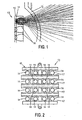
- FIG. 1 is a side view of a portion of a portion of a lighting fixture schematically illustrating an optical system according to an example embodiment of the present invention
- FIG. 2 is front view of a reflector array of the lighting fixture of FIG. 1 ;
- FIG. 3 is an isometric view of the reflector array of FIG. 2 , having the LEDs removed;
- FIG. 4 is a side view of an optical system according to an example embodiment of the present invention.
- FIG. 5 is a perspective view of a reflector array according to an example embodiment of the present invention.
- FIG. 6 is a schematic illustration of a control circuit for LEDs according to an example embodiment of the present invention.
- FIG. 7 is a schematic illustration of a control circuit for LEDs including a soft start function according to an example embodiment of the present invention.
- FIG. 8 is a broken sectional view of a metal core circuit board according to an example embodiment of the present invention.
- FIGS. 8a-8d illustrate steps in an example process of producing the metal core circuit board of FIG- 8;
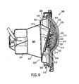
- FIG. 9 is a sectional view of an underwater pool lighting fixture according to an example embodiment of the present invention.
- FIG. 10 is a front view of the light fixture of FIG. 9 showing a lens thereof;
- FIG. 11 is a sectional view of the lens of FIG. 10 taken along section line 11-11 in FIG. 10 ;
- a submersible lighting fixture for a swimming pool, spa, or other application.
- the lighting fixture generally includes an light-emitting diode (LED) lamp assembly, a reflector array, a housing, a lens, and a heat dissipation assembly.
- the lamp includes an array of red, blue, and green LEDs. By controlling and mixing the output of the LEDs, the lighting fixture produces light of varying colors.
- FIGS. 1-4 schematically illustrate various aspects of an optical system according an example embodiment of the present invention.
- the optical system is designed to shape and condition a light beam of a submersible lighting fixture to provide generally even illumination of walls and a floor of basin containing water, such as a swimming pool, spa or the like (not shown).
- FIG. 1 is a side cross-section of a portion of a lighting fixture, which schematically illustrates a reflector array 10, a transparent cover or lens 12 and an LED light source 13 including LEDs 14.
- an example reflector array 10 includes rows of reflective and refractive surfaces 16.
- the LED light source 13 includes an array of the LEDs 14 arranged in rows 17.
- Each row 17 of LEDs 14 is positioned adjacent to one or more reflective and refractive surfaces 16, which are curved and/or flat, and are arranged to collect light emitted from the each row 17 of the LEDs 14 and to shape and direct the light for passage through the lens 12.
- the lens 12 is shaped to provide favorable refraction and reflection of the light beams so that, upon entering water, the beams are directed to give generally even illumination of the pool or spa walls and floor while presenting reduced spot intensity from an LED 14.
- each LED 14 in a generally conical pattern, which is not suitable for illuminating the walls and floor of either a swimming pool or spa.
- the LEDs 14 are arranged in an array of horizontal rows 17. Rays from each row impinge on reflective surfaces 16 which shape the beam of light emanating from the array.
- the lens 12 is shaped so that rays traveling upward are refracted only slightly and rays traveling downwards are disturbed minimally, Rays are restricted in upward angle to minimize the light that is lost out the top of the water surface.
- the rays pass through the lens 12 and are refracted again at the lens/water interface.
- the lens 12 can be made of any suitable material, including plastic, glass, or the like.
- the rays then pass through the water to the walls and floor of the pool or spa. If the lighting fixture was not submersed, the beam pattern would be different.
- FIG. 4 shows a top view in which the reflector array 10 has been removed for the sake of clarity.
- the lens 12 is constructed so as to have numerous vertical projections or ribs 18 that serve to refract the rays horizontally.
- a plurality of vertically extending projections or ribs 18 provided on the inside surface of the lens 12.
- a row 20 of three LEDs 14R, 14G, 14B of different colors or wavelengths, for example red, green and blue, is shown in which the light emitted is being refracted horizontally by the lens 12. This further shapes the beam to match the walls and floor of the pool or spa.
- the refraction also causes rays from several LEDs in each row 20 to arrive at a typical eye position of an observer 22, if one is positioned to see into the lighting fixture.
- the effect is one of "smearing" the light horizontally and creating a much larger apparent source. This decreases apparent intensity to a more comfortable level.
- the light intensity emanating from the light fixture is reduced to a comfortable level by optically increasing the area of the light source.
- the LED array is a large light source which is shaped by the reflector array to match the pool or spa cross section. Minimal light is lost out of the upper water surface-
- the lens 12 is shaped to refract the light towards the desired wall and floor surfaces to minimize bright and dark spots.
- FIG. 5 shows a reflector array 10' according to an alternative embodiment of the present invention.
- the reflector array 10' includes reflective and refractive surfaces 16'. It should be appreciated that other reflector arrays having differently shaped reflective and refractive surfaces can be provided according to the present invention.
- a lighting fixture includes two circuit boards on which LEDs and their power and control circuitry are provided.
- One circuit board contains the LEDs and their current drivers and current-sourcing Darlington transistors, along with other associated electrical components.
- the other board contains rectifier and voltage regulation circuitry, a microcontroller or microprocessor, and two multiplexers or serial-to-parallel converters-
- the boards are joined by two 24-pin headers that are soldered to each board. The headers act as stand-offs, separating the two boards.
- Individual LEDs are switched on and off by the current-sourcing Darlington transistors.
- the transistors are controlled by the microcontroller via the serial-to-parallel converters.
- An LED is turned on when the base of its current-sourcing transistor is switched from a positive voltage to ground by its serial-to-parallel converter. Conversely, an LED is turned off when the base of its current-sourcing transistor is switched from ground to the positive voltage.
- Each LED's anode is connected to a current-sourcing transistor and its cathode connected to ground.
- the number of LEDs of a particular color that are simultaneously turned on determines the intensity of that color. Individual LEDs are turned on and off as necessary to vary the intensity of each color and, therefore, the overall color that is produced by the present invention. All on-and-off switching of the LEDs occurs at frequencies perceptible to the human eye.
- the example embodiment of the present invention can sequentially change the colored light that it produces.
- color sequencing is achieved by turning on and off LEDs according to a routine performed by the microcontroller.
- the microcontroller uses a lookup table in performing the routine.
- the lookup table contains numerical values that represent the on or off states of the LEDs at various points in the sequence.
- FIG. 6 shows a control circuit 100 for controlling a plurality of LEDs 101.
- the circuit can be used for pool and spa lights and landscaping lights or wherever light output control ' of LEDs is desired.
- the light will illuminate the pool or spa walls with a variety of colors of light provided by combining red, blue, and green LEDs.
- the circuit 100 controls an array of LEDs 101 by turning individual LEDs 101 on and off, while providing the required current and voltage to the LED(s) 101 presently turned on.
- a microcontroller or microprocessor U1 receives color output value/mode selection commands by means of AC (alternating current) line changes. Further, an AC line input is rectified by a rectifier section 102 which feeds each of a number of LED driver circuits 107.
- Each driver circuit 107 includes a filter capacitor 104, a step-down constant voltage circuit 106 and a constant current driver U3.
- the filter capacitor 104 filters the AC output from the rectifier section 102 and applies it to the step-down circuit 106, which provides the necessary current to the constant current driver U3.
- Each of the constant current drivers U3 can be configured for specific voltages or current differences based upon the particular requirement of the LED 101 connected thereto. For example, the value of a current adjust resistor R CA is selected to cause the constant current driver U3 to provide the appropriate current for the LED 101 connected thereto.
- the constant current driver U3 of each LED driver circuit 107 is switched on or off by one or more serial-to-parallel converters U2.
- the microcontroller U1 outputs a serial word that represents which LEDs 101 are to be switched on or off, for the color output currently selected.
- the microcontroller U1 controller its output to provide a variety of different static and dynamic color shows based on the commands it receives. For example, any combination of red, blue or green LEDs 101 can be powered on or off with this method.
- the circuit 100 is fully scalable to control more or less LEDs 101 by connecting the microcontroller U1 to more or less serial-to-parallel converters U2, which in turn can be connected to more or less current drivers U3.
- the circuit 100 By turning on more or less LEDs of a particular color, the circuit 100 according to the example embodiment of the present invention effectively controls the intensity of light that is output of a particular color without controlling the duty cycle or otherwise controlling the intensity of individual LEDs.
- the circuit 100 provides a constant current via an analog controlled current source.
- an example embodiment includes fade-in and fade-out control of the LEDs. Fade-in is achieved by selectively turning on individual LEDs at different times. Similarly, fade-out is achieved by selectively turning off individual LEDs at different times.
- the present invention further includes capacitors for the soft starting and stopping of each individual LED. Each current-sourcing Darlington transistor has a capacitor connected to its base for the soft starting and stopping its associated LED. The capacitor respectively discharges and charges over time when the microcontroller through the serial-to-paraliel converter, attempts to turn the LED on and off, which results in the soft starting and stopping of the LED.
- a control circuit 100' includes an LED driver 107A-107E and a ramping circuit 108A-108E for each of a plurality of LEDs 101A-101E.
- the LED drivers 107A-107E operate similarly to the LED driver circuit 107 described above with respect to the embodiment of FIG. 6 - Differences between the example embodiment of FIG. 7 and the embodiment of FIG. 6 will become more apparent from the following disclosure. Further, more specific details of operation will be discussed below with reference to an exemplary LED 101A, an exemplary LED driver 107A, and an exemplary ramping circuit 108A. Additionally, while the LED drivers 107B-107E and the ramping circuits 108B-108E are each shown schematically in FIG.
- each of the LED drivers 107B-107E, each of the ramping circuits 108B-108E and each of the LEDs 101B-101E operate substantially the same as the exemplary LED driver 107A, ramping circuit 108A and the associated LED 101A.
- the LED driver and ramping circuit 108A causes the LED 101A to turn on slowly and to turn off slowly.
- the ramping circuit 108A includes a transistor Q1, resistor R1 and capacitor C1.
- the ramp up and down of the current is a fixed time selected by component values.
- the ramping of LEDs 101 as perceived by the human eye is a soft start and a soft stop of the individual LEDs.
- This circuit receives a constant current from the linear constant current source U3 and provides the current to the LEDs 101 at a ramp rate set by the resulting time constant based on the value of the resistor R1 and the value of the capacitor C1.
- the current output of the transistor Ql is controlled by R1 and C1 output.
- Each LED 101 has its own ramping circuit 108A.
- the individual LED selection is done by the microcontroller U1 and the serial to parallel converter U2 (see FIG. 6 ).
- the number of LEDs required to be controlled will dictate the number of components required. Additional serial to parallel converters U2, LED driver circuits and ramping circuits can be added as more LEDs are required.
- FIG. 8 illustrates a multilayer metal-core circuit board 200, according to the present invention, for providing thermal management for optimal performance of LEDs.
- the circuit board 200 accommodates heat generating electrical components on both sides.
- LEDs can be provided on one side 202 of the circuit board 200 and control, driver or other circuits on the other side 204.
- the circuit board 200 has a heat-dissipating metal core 206, made of copper for example, that is sandwiched between two thermally-conductive dielectric substrates or layers 208, 210.
- the dielectric substrates 208, 210 can be made from any suitable material having suitable electrically insulating or dielectric properties and having a sufficient thermal conductivity, for example greater than 1 W/m-°C.
- An example of a suitable material is "T-preg 1KA Dielectric" available from Laird Technologies of Cleveland, Ohio which as a thermal conductivity of approximately 3 W/m-°C.
- An electrically conductive layer 212, 214 such as a copper foil, is provided on the outside of each dielectric substrate 208, 210.
- the electrically conductive layers 212, 124 can be etched using photoresistive or other suitable conventional etching techniques to form conductive circuit traces.
- the top electrically conductive layer 212 supports LEDs and the bottom electrically conductive layer 214 supports the control and driver circuits.
- Plated through-holes or "via" holes 216 are provided for connection of components from the LED side 202 to the controller/driver circuit side 204 thru the metal core 206.
- FIGS. 8a-8d illustrate an example process for producing the circuit board 200 shown in FIG. 8 .
- core holes 218 are drilled in the metal core 206.
- the core holes 218 have diameters that are larger than the desired diameter of the through-holes 216.
- An electrically insulating resin or other material for example "T-preg" available from Laird Technologies of Cleveland, Ohio, is applied to both sides of the metal core 206.
- the electrically insulating material 220 fills the core boles 218 drilled in the metal core 206.
- the application also results in a thin coating (not shown) of the insulating material on both sides of the metal core 206.
- the metal core 206 is then assembled with the other layers 208-214 in any appropriate order.
- the first dielectric substrate 208 is bonded to a first side of the metal core 206 using an appropriate adhesive.
- the second dielectric substrate 210 is similarly bonded to a second side of the metal core 206.
- the first electrically conductive layer 212 is bonded to the exposed side of the first dielectric substrate 208 using an appropriate adhesive.
- the second electrically conductive layer 214 is bonded to the exposed side of the second dielectric substrate 210.
- the through-holes 216 are then drilled in the metal core board 200 at the same locations as the core holes 218 that were drilled in the metal core 206, but with a drill bit having a smaller diameter.
- Each of the cores holes 18, which is now filed with the electrically insulating material 220, circumscribes a corresponding one of the core holes 218.
- the through-hole extends through the first electrically conductive layer 212, the first dielectric substrate 208, the metal core 206, the second dielectric substrate 210, and the second electrically conductive layer 214.
- tubular-shaped insulating layers or electrical insulators 220a are formed from the electrically insulating material 220 left in the core holes 218.
- the through-holes 216 are then filled with conductive solder 222 that plates the inside of the through-holes 216, connecting the LED side 202 to the controller/driver circuit side 204 of the circuit board 200.
- the metal core 206 remains electrically isolated from the conductive solder 222 by the electrical insulators 220a.
- Each of the electrical insulators 220a is positioned inside of one of the through-holes 216 and is interposed between the metal core 206 and the conductive solder 222.
- the conductive solder 222 acts as a conductor for electrically connecting the first electrically conductive layer 212 to the second electrically conductive layer 214.
- a wire or other conductor can be inserted through the through-hole 216 and connected between the first electrically conductive layer 212 and the second electrically conductive layer 214.
- the wire or other conductor can be provided with an insulating sheath, which eliminates the need for both the solder 222 and the electrical insulators 220a.
- commands for controlling the lighting fixture according to the present invention are communicated to a controller through power interruptions on a supply power line.
- the controller responds to the commands that it receives to control the LEDs.
- Multiple lighting fixtures according to the present invention that are connected to the same supply power will receive the same commands through power interruptions and will respond in the same way. Examples of controlling lighting fixtures by using power interruptions can be found in U.S. Patent Nos. 6,002,216 and 6,379,025 , which are incorporated herein by reference.
- an underwater lighting fixture 300 includes a metal housing 302 which defines an interior cavity .
- the housing 302 has a front portion 304, a middle portion 305 and a rear portion 306.
- the front portion 304 is generally cylindrical and the rear portion 306 is also generally cylindrical, but has a smaller diameter.
- the middle portion 305 is generally frustoconical.
- the front and middle portions 304, 305 are joined by a step portion 308.
- the step portion 308 is provided with four forwardly projecting posts 310.
- the lighting fixture 300 further includes a first generally rectangular circuit board 312 and a second generally rectangular circuit board 313.
- the first circuit board 312 contains a plurality of LEDs 314 and a portion of a control circuit that selectively provides power to the LEDs 314.
- the first circuit board could include the LED driver 107 shown in FIG. 6 or the LED drivers 107A-107E with the ramping circuits 108A-108E shown in FIG. 7 .
- the first circuit board 312 is a metal core printed circuit board similar to the metal core board 200 shown and described above with reference to FIG. 8 .
- the LEDs 314 are mounted on one face 316 of the circuit board 312.
- the second circuit board contains other components of the control circuit, for example the rectifiers 102, the microcontroller U1, and the multiplexers U2 shown in FIGS. 6 and 7 .
- a reflector array 318 similar to the reflector array 10 shown and described above with reference to FIGS. 1-3 is mounted on the same face 316 of the board where the LEDs 314 are mounted.
- the reflector array 318 has the form of a grid and the LEDs 314 are located in openings 320 of the grid.
- the lighting fixture 300 also includes a heat sink 322-
- the heat sink 322 has a first mounting portion or flange 324 and a second mounting portion or flange 326.
- the first mounting flange 324 is generally circular and has four holes (not shown) corresponding to the four posts 310 of the housing 302.
- the fist mounting flange 324 is secured to an inside surface of the step portion 308 of the housing 302 using the posts 310 or, alternatively, by another suitable method of attachment.
- the second mounting flange 326 is generally rectangular.
- the first circuit board 312 and the second circuit board 313 are mounted on opposite sides of the second mounting flange 326.
- the first circuit board 312 and second circuit board 313 are connected electrically by pins of a 60-pin header 328 that are soldered to each board 312, 313.
- the header 328 also acts as a stand-off, physically separating the two boards 312,313.
- a transparent cover or lens 330 is attached to the front portion 304 of the housing 302.
- the lens extends across and covers a generally circular opening defined by the front portion 304.
- the lens 330 is similar to the lens 12 shown in FIG. 4 .
- the lens 330 has a series of vertically projections or ribs 332 that serve to refract light rays emitted from the LEDs 314 in a horizontal direction, as explained above with regard to FIG. 4 .
Landscapes
- Engineering & Computer Science (AREA)
- General Engineering & Computer Science (AREA)
- Physics & Mathematics (AREA)
- Geometry (AREA)
- Microelectronics & Electronic Packaging (AREA)
- Non-Portable Lighting Devices Or Systems Thereof (AREA)
- Arrangement Of Elements, Cooling, Sealing, Or The Like Of Lighting Devices (AREA)
- Fastening Of Light Sources Or Lamp Holders (AREA)
- Radiation-Therapy Devices (AREA)
- Led Devices (AREA)
Claims (28)
- Eine Lichtbefestigung (300) umfassend:ein Gehäuse (302) mit einem inneren Hohlraum (303) und eine Öffnung (320);eine transparente Abdeckung (330), die an das Gehäuse (302) angebracht ist, und die Öffnung (320) abdeckt;eine Wärmesenke (322), die ein erstes Montageteil (324) und ein zweites Montageteil (326) enthält, das erste Montageteil (324) ist an das Gehäuse (302) in dem inneren Hohlraum (303) angebracht, das zweite Montageteil (326) hat eine erste Seite und einer zweite Seite gegenüber der ersten Seite;gekennzeichnet durch
eine erste Schaltkreisplatine (312), die auf der ersten Seite des zweiten Montageteils (326) montiert ist, wobei die erste Schaltkreisplatine (312) einen Wärme leitenden, metallischen Kern (206) umfasst,
ein Lichtaufbau, das ein LED Lichtquelle enthält, die LED Lichtquelle enthält eine Vielzahl von LEDs (14, 314), die auf der ersten Schaltkreisplatine (312) montiert sind; und
eine zweite Schaltkreisplatine (313), die auf der zweiten Seite des zweiten Montageteils (326) montiert ist, die zweite Schaltkreisplatine (313) enthält mindestens ein Teil eines Kontrollschaltkreises (100), der Kontrollschaltkreis (100) ist operativ mit der LED Lichtquelle verbunden, um selektiv Leistung zu jeder der Vielzahl von LEDs (14, 314) bereitzustellen,
wobei die Wärme, die durch die LEDs (14, 314) erzeugt wird, und die Wärme erzeugenden Komponenten des Kontrollschaltkreises (100) durch den metallischen Kern (206) der ersten Schaltkreisplatine (312) zu der Wärmesenke (322) geleitet werden. - Die Lichtbefestigung (300) gemäss Anspruch 1, weiter umfassend eine Stiftleiste (328), das eine Vielzahl von Pins enthält, um die erste Schaltplatine (312) und die zweite Schaltplatine (313) elektronisch zu verbinden.
- Die Lichtbefestigung (300) gemäss Anspruch 2, wobei das Kopfelement (328) weiter als ein Abstand agiert, um die erste Schaltplatine (312) von der zweiten Schaltplatine (313) zu trennen.
- Die Lichtbefestigung (300) gemäss Anspruch 1, wobei die Lichtbefestigung (300) für einen Betrieb angepasst ist, während das Gehäuse (302) im Wasser eingetaucht ist, so dass die Wärme, die durch die LEDs (14, 314) und die Kontrollschaltkreise (100) erzeugt wird, zu der Wärmesenke (322) geleitet wird, die Wärmesenke (322) leitet die Wärme zu dem Gehäuse (302) und das Gehäuse (302) leitet die Wärme zu dem Wasser.
- Die Lichtbefestigung (300) gemäss irgendeinem der Ansprüche 1 bis 4, wobei die erste Schaltkreisplatine (312) umfasst:der Wärme leitende Kern (206) hat eine erste Seite und eine zweite Seite gegenüber der ersten Seite (202);ein erstes dielektrisches Substrat (208) mit einer Aussenseite und einer Innenseite gegenüber der Aussenseite, , die Innenseite ist zu der ersten Seite des Wärme leitenden Kerns (206) befestigt;eine erste elektrische leitende Schicht (212), die an die Aussenseite des ersten dielektrischen Substrates (208) befestigt ist;ein zweites dielektrisches Substrat (210) mit einer Aussenseite und einer Innenseite gegenüber der Aussenseite, die Innenseite ist an die zweite Seite des Wärme leitenden Kerns (206) befestigt;eine zweite elektrisch leitende Schicht (214), die an der Aussenseite des zweiten dielektrischen Substrates (210) befestigt ist,ein Durchgangsloch (216), das sichdurch die erste elektrische Schicht (212), das erste dielektrische Substrat (208), den Wärmeleitenden Kern (206), das zweite dielektrische Substrat (210) und den zweiten elektrisch leitende Schicht (214) erstreckt;einen elektrischen Leiter (222), der sich durch das Durchgangsloch (216) erstreckt, und ein erstes Ende hat, das elektrisch mit der ersten elektrisch leitenden Schicht (212) verbunden ist, und ein zweites Ende, das mit der zweiten elektrisch leitenden Schicht (214) verbunden ist, wobei eine elektrische Verbindung zwischen der ersten elektrisch leitenden Schicht (212) und der zweiten elektrisch leitenden Schicht (21) bereitgestellt wird; undeinen elektrischen Isolator (220, 220a), die in dem Durchgangsloch (216) vorgesehen ist, und zwischen dem Wärme leitenden Kern (206) und dem elektrischen Leiter (222) gestellt ist, um den Wärme leitenden Kern (206) von dem elektrischen Leiter (222) elektrisch zu isolieren,wobei das erste dielektrische Substrat (208) und das zweite dielektrische Substrat (210) thermisch leitend sind.
- Die Lichtbefestigung (300) gemäss Anspruch 5, wobei das erste dielektrische Substrat (208) und das zweite dielektrische Substrat (210) eine thermische Leitfähigkeit von ungefähr 3 W/m-°C haben
- Die Lichtbefestigung (300) gemäss Anspruch 5, wobei der Wärme leitende Kern (206) Metall ist.
- Die Lichtbefestigung (300) gemäss Anspruch 7, wobei das Metall Kupfer umfasst / beinhaltet.
- Die Lichtbefestigung (300) gemäss Anspruch 5, wobei der elektrische Leiter ein Lot (222) ist, welches an die Innenseite des Durchgangslochs (216) aufgebracht ist.
- Die Lichtbefestigung (300) gemäss Anspruch 5, wobei der elektrische Isolator (220, 220a) ein Harz enthält.
- Die Lichtbefestigung (300) gemäss Anspruch 5, weiter umfassend ein Loch (218) in dem Wärme leitenden Kern (206), welcher das Durchgangsloch (216) abgrenzt, wobei der elektrische Isolator (220, 220a) in einem Platz vorgesehen ist, der zwischen dem Durchgangsloch (216) und dem Loch (218) in dem in dem Wärme leitenden Kern (206).
- Die Lichtbefestigung (300) gemäss Anspruch 5, wobei jede der ersten elektrischen Schicht (212) und der zweiten elektrischen Schicht (214) einen elektrischen Schaltkreisverfolger enthält.
- Die Lichtbefestigung (300) gemäss Anspruch 1, umfassend
die LED-Lichtquelle (13) projiziert einen Lichtstrahl gegen die Öffnung (320), der Strahl enthält erster Lichtstrahlen, die hinauf zu der transparenten Abdeckung (330) projiziert werden, und zweite Lichtstrahlen, die hinunter zu der transparenten Abdeckung (330) projiziert werden,
wobei die transparente Abdeckung (330) so geformt ist, dass die zweiten Lichtstrahlen mehr als die ersten Lichtstrahlen gebrochen werden. - Die Lichtbefestigung (300) gemäss Anspruch 13, in welcher die Lichtbefestigung (330) angepasst ist, um in einem Schwimmbad oder Spa montiert zu werden, so dass mindestens einige der ersten Lichtstrahlen gegen die obere Oberfläche des Wassers projiziert werden, und wobei mindestens einige der zweiten Lichtstrahlen hinunter zu der unteren Oberfläche oder dem Boden des Schwimmbades oder Spas projiziert werden.
- Die Lichtbefestigung (300) gemäss Anspruch 1, weiter umfassend
die transparente Abdeckung (330) enthält eine Vielzahl von vertikalen, sich ausdehnenden Projektionen, die über eine Oberfläche der transparenten Abdeckung (330) verteilt ist; und
eine Vielzahl von Lichtquellen, um einen Lichtstrahl gegen die Öffnung (320) zu projizieren;
wobei die Projektionen (18) geformt sind, um den Lichtstrahl horizontal abzulenken. - Die Lichtbefestigung (300) gemäss Anspruch 15, weiter umfassend eine Vielzahl von Lichtquellen, die in einer horizontalen Reihe angeordnet sind, um einen Lichtstrahl gegen die Öffnung zu projizieren, eine erste von der Vielzahl von Lichtquellen strahlt erste Lichtwellen aus und eine zweite von einer Vielzahl von Lichtquellen strahlt zweite Lichtwellen mit einer Wellenlänge, die verschieden ist von einer Wellenlänge der ersten Lichtwellen.
- Die Lichtbefestigung (300) gemäss Anspruch 16, wobei die Projektionen (18) geformt sind, um die erste Lichtwellen und die zweiten Lichtwellen horizontal zu brechen, um einen Lichtstrahl zu produzieren, der die ersten und zweiten Lichtwellen enthält.
- Die Lichtbefestigung (300) gemäss Anspruch 15, wobei die Lichtquelle einen Reflektor (16, 16') enthält.
- Die Lichtbefestigung (300) gemäss Anspruch 1, weiter umfassend:ein Reflektorgitter (10, 10') enthaltend eine Vielzahl von Reflektoren, jeder der Vielzahl von Reflektoren enthält ein ersten offenes Ende, ein zweites offenes Ende, und erste und zweite reflektierende Oberflächen (16, 16'), die sich zwischen dem ersten offenen Ende und dem zweiten offenen Ende erstrecken, die erste reflektive Oberfläche liegt gegenüber der zweiten reflektiven Oberfläche (16, 16');eine Lichtquelle umfassend eine Vielzahl von LEDs-Reihen (14), jede enthält eine Vielzahl von LEDS (14), jede Reihe (17) projiziert Licht in die erste offene Ende von einem assoziierten von der Vielzahl von Reflektoren, wobei das Licht, das von jedem der Reihe von LEDs (14) projiziert wird, durch die erste und zweite reflektierende Oberfläche (16, 16') von dem assoziierten Reflektor reflektiert wird, was verursacht, dass das Licht durch das zweite offene Ende des assoziierten Reflektors und durch die transparente Abdeckung (330) strömt.
- Die Lichtbefestigung (300) gemäss Anspruch 19, in welcher jeder der ersten und zweiten reflektierenden Oberflächen (16, 16') konkav ist.
- Die Lichtbefestigung (300) gemäss Anspruch 19, in welcher die Lichtquelle (13) mit einem Reflektorgitter (10, 10') zusammenarbeitet, um ein Lichtstrahl zu einer Öffnung (320) des Gehäuses (302) zu projizieren, der Strahl enthält erste Lichtstrahlen, die hinaus zu der transparenten Abdeckung (330) projizieren, und zweite Lichtstrahlen, die hinunter zu der transparenten Abdeckung (330) projizieren, und wobei die transparente Abdeckung (330) geformt ist, um die zweiten Lichtstrahlen mehr abzulenken als die zweiten Lichtstrahlen.
- Die Lichtbefestigung (300) gemäss Anspruch 1, weiter umfassend:der Kontrollschaltkreis (100) enthält:wobei der Mikrokontroller (U1) individuell und selektiv Leistung zu jeder der Vielzahl von LEDs (14) zu kontrollieren.einen Mikrokontroller (U1) mit einem Eingang, der verbunden ist, eine Wechselstromquelle zu lesen, und eine Vielzahl von Ausgängen, um die Vielzahl von LEDs (14) zu kontrollieren;eine Vielzahl von Multiplexern, jeder mit einer Vielzahl von Ausgängen und einem Eingang, der mit einer der Vielzahl von Ausgängen des Mikrokontrollers (U1) verbunden ist; undeine Vielzahl von elektronischen Schalter, jeder mit einem Kontrolleingang und einem Leistungsausgang, jeder Leistungsausgang ist verbunden, um selektiv zu einer der Vielzahl der LEDs (14) Strom zuzuführen, jeder der Kontrollinputs ist mit einer der Vielzahl von Ausgängen von einem der Vielzahl der Multiplexer verbunden,
- Die Lichtbefestigung (300) gemäss Anspruch 22, in welcher der Kontrollschaltkreis (100) weiter eine Vielzahl von Stromtreibern (U3) enthält, jeder der Vielzahl von Stromtreibern (U3) enthält einen von der Vielzahl von elektronischen Schaltern.
- Die Lichtbefestigung (300) gemäss Anspruch 23, weiter umfassend ein Kopfelement (328) enthaltend eine Vielzahl von Pins, um die erste Schaltkreisplatine (312) und die zweite Schaltkreisplatine (313) zu verbinden.
- Die Lichtbefestigung (300) gemäss Anspruch 24, in welcher das Kopfelement (328) weiter als ein Abstand agiert, um physisch die erste Schaltkreisplatine (312) von der zweiten Schaltkreisplatine (313) zu trennen.
- Die Lichtbefestigung (300) gemäss Anspruch 22, in welcher der Kontrollschaltkreis (100) weiter eine Vielzahl von Rampenschaltkreisen enthält, um selektiv Leistung zu einer der Vielzahl von LEDs (14) über eine erste Zeitperiode aufzubauen, und selektiv Leistung zu einer der Vielzahl von LEDs (14) abzubauen, wobei jeder der Vielzahl der Rampenschaltkreise eine Vielzahl von elektronischen Schaltern enthält.
- Die Lichtbefestigung (300) gemäss Anspruch 26, in welcher jeder der Vielzahl vom Rampenschaltkreise eine Vielzahl von Zeitschaltkreisen beinhaltet, um den korrespondierenden elektronischen Schalter gemäss der ersten Zeitperiode und der zweiten Zeitperiode zu kontrollieren.
- Die Lichtbefestigung (300) gemäss Anspruch 27, in welcher jeder Zeitschaltkreis einen Kondensator (C1) und einen Widerstand (RCA) beinhaltet, wobei die erste Zeitperiode und die zweite Zeitperiode jeweils eine Funktion von einer Kapazität des Kondensators (C1) und eines Widerstands des Widerstands (RCA) sind.
Applications Claiming Priority (1)
| Application Number | Priority Date | Filing Date | Title |
|---|---|---|---|
| US73045705P | 2005-10-26 | 2005-10-26 |
Publications (3)
| Publication Number | Publication Date |
|---|---|
| EP1781072A2 EP1781072A2 (de) | 2007-05-02 |
| EP1781072A3 EP1781072A3 (de) | 2007-05-16 |
| EP1781072B1 true EP1781072B1 (de) | 2009-12-30 |
Family
ID=37561146
Family Applications (1)
| Application Number | Title | Priority Date | Filing Date |
|---|---|---|---|
| EP06122967A Not-in-force EP1781072B1 (de) | 2005-10-26 | 2006-10-26 | Schwimmbad- und Badleuchte mit LED |
Country Status (8)
| Country | Link |
|---|---|
| US (1) | US7628512B2 (de) |
| EP (1) | EP1781072B1 (de) |
| AT (1) | ATE454030T1 (de) |
| AU (1) | AU2006235806B2 (de) |
| CA (1) | CA2565644C (de) |
| DE (1) | DE602006011408D1 (de) |
| MX (1) | MXPA06012455A (de) |
| NZ (1) | NZ571827A (de) |
Cited By (2)
| Publication number | Priority date | Publication date | Assignee | Title |
|---|---|---|---|---|
| WO2012027780A1 (en) * | 2010-08-30 | 2012-03-08 | Spa Electrics Pty Ltd | An underwater light |
| AU2012325969B2 (en) * | 2011-10-19 | 2015-07-02 | Current Lighting Solutions, Llc | Reflector, illuminator and the use thereof |
Families Citing this family (52)
| Publication number | Priority date | Publication date | Assignee | Title |
|---|---|---|---|---|
| US8093620B2 (en) * | 2002-12-10 | 2012-01-10 | Galli Robert D | LED lighting assembly with improved heat management |
| US8733966B2 (en) | 2004-08-20 | 2014-05-27 | Mag Instrument, Inc. | LED flashlight |
| US7918591B2 (en) | 2005-05-13 | 2011-04-05 | Permlight Products, Inc. | LED-based luminaire |
| US7986112B2 (en) | 2005-09-15 | 2011-07-26 | Mag Instrument, Inc. | Thermally self-stabilizing LED module |
| US7575675B2 (en) | 2006-06-19 | 2009-08-18 | Pentair Water Pool And Spa, Inc. | Pool cleaner debris bag |
| ES2691029T3 (es) | 2006-11-28 | 2018-11-23 | Hayward Industries, Inc. | Sistema de iluminación subacuática programable |
| US8237382B2 (en) | 2007-02-13 | 2012-08-07 | Osram Ag | LED module and method for operating at least one LED |
| US20090034261A1 (en) * | 2007-08-01 | 2009-02-05 | Douglas Grove | Led light fixture |
| JP5555180B2 (ja) * | 2008-01-16 | 2014-07-23 | ライツ、 キャメラ、 アクション エルエルシイ | 水中使用可能な高照度光源アセンブリー |
| US8033677B1 (en) * | 2008-08-01 | 2011-10-11 | DeepSea Power and Light, Inc. | Deep submersible light with pressure compensation |
| US9022612B2 (en) * | 2008-08-07 | 2015-05-05 | Mag Instrument, Inc. | LED module |
| US20100226139A1 (en) | 2008-12-05 | 2010-09-09 | Permlight Products, Inc. | Led-based light engine |
| US8177141B2 (en) * | 2008-12-19 | 2012-05-15 | Zodiac Pool Systems, Inc. | Laminar deck jet |
| US8042748B2 (en) * | 2008-12-19 | 2011-10-25 | Zodiac Pool Systems, Inc. | Surface disruptor for laminar jet fountain |
| DE102008063369B4 (de) * | 2008-12-30 | 2016-12-15 | Erco Gmbh | Leuchte und Modulsystem für Leuchten |
| US9247598B2 (en) * | 2009-01-16 | 2016-01-26 | Mag Instrument, Inc. | Portable lighting devices |
| US8525432B2 (en) * | 2009-04-09 | 2013-09-03 | Usai, Llc. | System and method for controlling an output illumination level of a lighting system |
| US10352550B1 (en) * | 2009-07-29 | 2019-07-16 | Deepsea Power & Light Llc | Submersible LED light fixture with multilayer stack for pressure transfer |
| US20110110095A1 (en) * | 2009-10-09 | 2011-05-12 | Intematix Corporation | Solid-state lamps with passive cooling |
| IT1398090B1 (it) * | 2010-02-05 | 2013-02-07 | Eral Srl Unipersonale | Dispositivo di illuminazione subacque a led con sistema di dissipazione del calore |
| US20110267834A1 (en) | 2010-04-28 | 2011-11-03 | Hayward Industries, Inc. | Underwater Light Having A Sealed Polymer Housing and Method of Manufacture Therefor |
| US8968559B2 (en) | 2010-05-14 | 2015-03-03 | Pentair Water Pool And Spa, Inc. | Biodegradable disposable debris bag |
| US8616725B2 (en) * | 2010-09-17 | 2013-12-31 | Deep Sea Power & Light, Inc. | LED spherical light fixtures with enhanced heat dissipation |
| EP2628035A1 (de) | 2010-10-11 | 2013-08-21 | 3M Innovative Properties Company | Beleuchtungsvorrichtung mit einem viskoelastischen lichtleiter |
| US20120106149A1 (en) * | 2010-11-02 | 2012-05-03 | Fusion Pool Products Inc. | Underwater and landscape lighting system |
| US9074357B2 (en) | 2011-04-25 | 2015-07-07 | Delta Faucet Company | Mounting bracket for electronic kitchen faucet |
| US9574760B1 (en) | 2011-09-19 | 2017-02-21 | Deepsea Power & Light, Inc. | Light fixture with internally-loaded multilayer stack for pressure transfer |
| US8992051B2 (en) | 2011-10-06 | 2015-03-31 | Intematix Corporation | Solid-state lamps with improved radial emission and thermal performance |
| US20130088848A1 (en) | 2011-10-06 | 2013-04-11 | Intematix Corporation | Solid-state lamps with improved radial emission and thermal performance |
| US9057184B2 (en) | 2011-10-19 | 2015-06-16 | Delta Faucet Company | Insulator base for electronic faucet |
| CN104066319B (zh) * | 2011-12-14 | 2017-09-05 | 万斯创新公司 | 水产养殖照明装置和方法 |
| US9611982B2 (en) | 2011-12-29 | 2017-04-04 | Pentair Water Pool And Spa, Inc. | LED replacement light assembly with improved cooling features |
| US9039232B2 (en) | 2011-12-30 | 2015-05-26 | Wet | Underwater LED lights |
| WO2013110987A2 (en) | 2012-01-05 | 2013-08-01 | Breau Kenneth William | Powered apparatus for fluid applications |
| AU2013312793B2 (en) * | 2012-09-04 | 2017-08-10 | Pentair Water Pool And Spa, Inc. | Pool cleaner generator module with magnetic coupling |
| CN104582472B (zh) | 2012-09-04 | 2018-06-05 | 飞利浦灯具控股公司 | 园艺照明系统以及使用这种园艺照明系统的园艺生产设施 |
| US9333698B2 (en) | 2013-03-15 | 2016-05-10 | Delta Faucet Company | Faucet base ring |
| WO2014143779A2 (en) | 2013-03-15 | 2014-09-18 | Hayward Industries, Inc | Modular pool/spa control system |
| US10295167B2 (en) * | 2013-04-24 | 2019-05-21 | Xiaodong Xiang | Cooling mechanism for LED light using 3-D phase change heat transfer |
| US8967837B2 (en) * | 2013-08-01 | 2015-03-03 | 3M Innovative Properties Company | Solid state light with features for controlling light distribution and air cooling channels |
| US9554562B2 (en) | 2014-08-07 | 2017-01-31 | Once Innovations, Inc. | Lighting system and control for experimenting in aquaculture |
| US9970639B2 (en) * | 2014-12-18 | 2018-05-15 | Hubbell Incorporated | Circuit boards for LED-based light fixtures |
| CA2973916A1 (en) | 2015-01-14 | 2016-07-21 | Pentair Water Pool And Spa, Inc. | Debris bag with detachable collar |
| EP3405629A4 (de) | 2016-01-22 | 2020-01-22 | Hayward Industries, Inc. | Systeme und verfahren zur bereitstellung von netzwerkkonnektivität und fernüberwachung, optimierung und steuerung einer pool-/spa-ausrüstung |
| US11720085B2 (en) | 2016-01-22 | 2023-08-08 | Hayward Industries, Inc. | Systems and methods for providing network connectivity and remote monitoring, optimization, and control of pool/spa equipment |
| US11044895B2 (en) | 2016-05-11 | 2021-06-29 | Signify North America Corporation | System and method for promoting survival rate in larvae |
| US10393363B2 (en) | 2017-04-25 | 2019-08-27 | Delta Faucet Company | Illumination device for a fluid delivery apparatus |
| US11168876B2 (en) | 2019-03-06 | 2021-11-09 | Hayward Industries, Inc. | Underwater light having programmable controller and replaceable light-emitting diode (LED) assembly |
| WO2020181249A1 (en) * | 2019-03-06 | 2020-09-10 | Hayward Industries, Inc. | Underwater light having a replaceable light-emitting diode (led) module and cord assembly |
| CN110160014B (zh) * | 2019-05-23 | 2024-04-26 | 欧普照明股份有限公司 | 一种照明灯具 |
| EP3936758A1 (de) * | 2020-07-09 | 2022-01-12 | Pentair Water Pool and Spa, Inc. | Unterwasserleuchtenanordnung und -verfahren |
| US11353208B2 (en) | 2020-09-03 | 2022-06-07 | Innotec, Corp. | Underwater LED lamp |
Family Cites Families (25)
| Publication number | Priority date | Publication date | Assignee | Title |
|---|---|---|---|---|
| GB1137422A (en) | 1966-04-01 | 1968-12-18 | Egatube Ltd | Improvements in or relating to boxes for sockets, switches or the like electrical fittings |
| GB2020970B (en) | 1978-05-22 | 1982-10-13 | Mannall I U | Drying and treatment cubicle |
| US4168877A (en) * | 1978-06-27 | 1979-09-25 | Amp Incorporated | Single lever back plane connector system |
| SU889131A1 (ru) | 1980-03-19 | 1981-12-15 | Предприятие П/Я В-2085 | Фонтанное устройство |
| DE3135861A1 (de) | 1981-09-10 | 1983-03-24 | Friedrich Grohe Armaturenfabrik Gmbh & Co, 5870 Hemer | Auslaufarmatur fuer wasser |
| GB2137422B (en) * | 1983-03-30 | 1986-10-29 | Ferranti Plc | Printed circuit board |
| GB8324839D0 (en) | 1983-09-16 | 1983-10-19 | Lucas Ind Plc | Mounting carrier for microelectronic silicon chip |
| JP2760829B2 (ja) * | 1989-01-13 | 1998-06-04 | 株式会社日立製作所 | 電子基板 |
| EP0446365A4 (en) | 1989-09-29 | 1992-07-08 | Inax Corporation | Water discharging apparatus |
| JPH05202540A (ja) | 1992-01-28 | 1993-08-10 | Sekisui Chem Co Ltd | 照明具付き水栓金具 |
| US6639155B1 (en) * | 1997-06-11 | 2003-10-28 | International Business Machines Corporation | High performance packaging platform and method of making same |
| US6292901B1 (en) * | 1997-08-26 | 2001-09-18 | Color Kinetics Incorporated | Power/data protocol |
| US6936978B2 (en) * | 1997-08-26 | 2005-08-30 | Color Kinetics Incorporated | Methods and apparatus for remotely controlled illumination of liquids |
| US6967448B2 (en) * | 1997-08-26 | 2005-11-22 | Color Kinetics, Incorporated | Methods and apparatus for controlling illumination |
| US6781329B2 (en) * | 1997-08-26 | 2004-08-24 | Color Kinetics Incorporated | Methods and apparatus for illumination of liquids |
| JP3216626B2 (ja) * | 1999-01-20 | 2001-10-09 | 日本電気株式会社 | 増幅装置 |
| DE20007235U1 (de) | 1999-05-19 | 2000-07-27 | Agon Tech Corp., Chung-Ho, Taipeh | Allzwecklampe |
| US7233831B2 (en) * | 1999-07-14 | 2007-06-19 | Color Kinetics Incorporated | Systems and methods for controlling programmable lighting systems |
| US6379025B1 (en) * | 2000-03-31 | 2002-04-30 | Pacfab, Inc. | Submersible lighting fixture with color wheel |
| US6782309B2 (en) * | 2000-11-07 | 2004-08-24 | 9090-3493 Quebec, Inc. | SPA controller computer interface |
| US6801003B2 (en) * | 2001-03-13 | 2004-10-05 | Color Kinetics, Incorporated | Systems and methods for synchronizing lighting effects |
| US6964501B2 (en) * | 2002-12-24 | 2005-11-15 | Altman Stage Lighting Co., Ltd. | Peltier-cooled LED lighting assembly |
| US6984944B2 (en) * | 2003-01-14 | 2006-01-10 | John Garrity | Controlling device for use with exterior landscape lighting assemblies |
| US6867558B2 (en) * | 2003-05-12 | 2005-03-15 | General Electric Company | Method and apparatus for networked lighting system control |
| US7125146B2 (en) * | 2004-06-30 | 2006-10-24 | H-Tech, Inc. | Underwater LED light |
-
2006
- 2006-10-26 AT AT06122967T patent/ATE454030T1/de not_active IP Right Cessation
- 2006-10-26 MX MXPA06012455A patent/MXPA06012455A/es active IP Right Grant
- 2006-10-26 US US11/586,890 patent/US7628512B2/en active Active
- 2006-10-26 NZ NZ571827A patent/NZ571827A/en unknown
- 2006-10-26 AU AU2006235806A patent/AU2006235806B2/en not_active Ceased
- 2006-10-26 CA CA2565644A patent/CA2565644C/en not_active Expired - Fee Related
- 2006-10-26 DE DE602006011408T patent/DE602006011408D1/de active Active
- 2006-10-26 EP EP06122967A patent/EP1781072B1/de not_active Not-in-force
Cited By (2)
| Publication number | Priority date | Publication date | Assignee | Title |
|---|---|---|---|---|
| WO2012027780A1 (en) * | 2010-08-30 | 2012-03-08 | Spa Electrics Pty Ltd | An underwater light |
| AU2012325969B2 (en) * | 2011-10-19 | 2015-07-02 | Current Lighting Solutions, Llc | Reflector, illuminator and the use thereof |
Also Published As
| Publication number | Publication date |
|---|---|
| CA2565644A1 (en) | 2007-04-26 |
| ATE454030T1 (de) | 2010-01-15 |
| EP1781072A2 (de) | 2007-05-02 |
| AU2006235806B2 (en) | 2011-12-08 |
| NZ571827A (en) | 2010-03-26 |
| MXPA06012455A (es) | 2007-04-25 |
| US20070159833A1 (en) | 2007-07-12 |
| CA2565644C (en) | 2014-05-20 |
| US7628512B2 (en) | 2009-12-08 |
| DE602006011408D1 (de) | 2010-02-11 |
| AU2006235806A1 (en) | 2007-05-10 |
| EP1781072A3 (de) | 2007-05-16 |
Similar Documents
| Publication | Publication Date | Title |
|---|---|---|
| CA2565644C (en) | Led pool and spa light | |
| JP5941134B2 (ja) | 照明モジュール | |
| EP2646743B1 (de) | Beleuchtungskörper | |
| CA2833344C (en) | Light emitting diode replacement lamp | |
| US7303301B2 (en) | Submersible LED light fixture | |
| US7410268B2 (en) | Light emitting diode pool assembly | |
| US9482396B2 (en) | Integrated linear light engine | |
| US7204608B2 (en) | Variable color landscape lighting | |
| EP2261550A2 (de) | Zerlegbare led-leuchten | |
| US20080123340A1 (en) | Light device having LED illumination and electronic circuit board in an enclosure | |
| EP1847759A2 (de) | LED-Leuchte mit Mehrfach-Chip | |
| WO2015184129A1 (en) | Area luminaire with heat fins | |
| CN1518768A (zh) | 用于局部照明的高功率led模块 | |
| WO2008066834A2 (en) | A light device having led illumination and an electronic circuit board | |
| US20130063946A1 (en) | Lighting apparatus | |
| JP2021522690A (ja) | 動的に制御可能な光分布を有する照明器具 | |
| KR101384955B1 (ko) | 조명기구 | |
| KR101004859B1 (ko) | 조명기구용 배선 일체형 천정판 및 그 천정판을 이용한 조명 방법 | |
| WO2014083760A1 (ja) | 照明器具および補助光源ユニット | |
| JP2002312892A (ja) | 発光体および信号灯 | |
| JP7312847B2 (ja) | 色混合のための多層pcbスタック | |
| JP2011049123A (ja) | 照明装置 | |
| JP6310588B2 (ja) | 照明装置 | |
| US11249239B2 (en) | Waveguide managing high power density | |
| CN210109969U (zh) | 光学信号装置 |
Legal Events
| Date | Code | Title | Description |
|---|---|---|---|
| PUAI | Public reference made under article 153(3) epc to a published international application that has entered the european phase |
Free format text: ORIGINAL CODE: 0009012 |
|
| PUAL | Search report despatched |
Free format text: ORIGINAL CODE: 0009013 |
|
| AK | Designated contracting states |
Kind code of ref document: A2 Designated state(s): AT BE BG CH CY CZ DE DK EE ES FI FR GB GR HU IE IS IT LI LT LU LV MC NL PL PT RO SE SI SK TR |
|
| AX | Request for extension of the european patent |
Extension state: AL BA HR MK YU |
|
| AK | Designated contracting states |
Kind code of ref document: A3 Designated state(s): AT BE BG CH CY CZ DE DK EE ES FI FR GB GR HU IE IS IT LI LT LU LV MC NL PL PT RO SE SI SK TR |
|
| AX | Request for extension of the european patent |
Extension state: AL BA HR MK YU |
|
| 17P | Request for examination filed |
Effective date: 20071023 |
|
| 17Q | First examination report despatched |
Effective date: 20071213 |
|
| AKX | Designation fees paid |
Designated state(s): AT BE BG CH CY CZ DE DK EE ES FI FR GB GR HU IE IS IT LI LT LU LV MC NL PL PT RO SE SI SK TR |
|
| GRAP | Despatch of communication of intention to grant a patent |
Free format text: ORIGINAL CODE: EPIDOSNIGR1 |
|
| GRAS | Grant fee paid |
Free format text: ORIGINAL CODE: EPIDOSNIGR3 |
|
| GRAA | (expected) grant |
Free format text: ORIGINAL CODE: 0009210 |
|
| AK | Designated contracting states |
Kind code of ref document: B1 Designated state(s): AT BE BG CH CY CZ DE DK EE ES FI FR GB GR HU IE IS IT LI LT LU LV MC NL PL PT RO SE SI SK TR |
|
| REG | Reference to a national code |
Ref country code: GB Ref legal event code: FG4D |
|
| REG | Reference to a national code |
Ref country code: CH Ref legal event code: EP |
|
| REG | Reference to a national code |
Ref country code: IE Ref legal event code: FG4D |
|
| REF | Corresponds to: |
Ref document number: 602006011408 Country of ref document: DE Date of ref document: 20100211 Kind code of ref document: P |
|
| PG25 | Lapsed in a contracting state [announced via postgrant information from national office to epo] |
Ref country code: LT Free format text: LAPSE BECAUSE OF FAILURE TO SUBMIT A TRANSLATION OF THE DESCRIPTION OR TO PAY THE FEE WITHIN THE PRESCRIBED TIME-LIMIT Effective date: 20091230 Ref country code: SE Free format text: LAPSE BECAUSE OF FAILURE TO SUBMIT A TRANSLATION OF THE DESCRIPTION OR TO PAY THE FEE WITHIN THE PRESCRIBED TIME-LIMIT Effective date: 20091230 Ref country code: FI Free format text: LAPSE BECAUSE OF FAILURE TO SUBMIT A TRANSLATION OF THE DESCRIPTION OR TO PAY THE FEE WITHIN THE PRESCRIBED TIME-LIMIT Effective date: 20091230 |
|
| REG | Reference to a national code |
Ref country code: NL Ref legal event code: VDEP Effective date: 20091230 |
|
| LTIE | Lt: invalidation of european patent or patent extension |
Effective date: 20091230 |
|
| PG25 | Lapsed in a contracting state [announced via postgrant information from national office to epo] |
Ref country code: LV Free format text: LAPSE BECAUSE OF FAILURE TO SUBMIT A TRANSLATION OF THE DESCRIPTION OR TO PAY THE FEE WITHIN THE PRESCRIBED TIME-LIMIT Effective date: 20091230 Ref country code: SI Free format text: LAPSE BECAUSE OF FAILURE TO SUBMIT A TRANSLATION OF THE DESCRIPTION OR TO PAY THE FEE WITHIN THE PRESCRIBED TIME-LIMIT Effective date: 20091230 Ref country code: PL Free format text: LAPSE BECAUSE OF FAILURE TO SUBMIT A TRANSLATION OF THE DESCRIPTION OR TO PAY THE FEE WITHIN THE PRESCRIBED TIME-LIMIT Effective date: 20091230 |
|
| PG25 | Lapsed in a contracting state [announced via postgrant information from national office to epo] |
Ref country code: AT Free format text: LAPSE BECAUSE OF FAILURE TO SUBMIT A TRANSLATION OF THE DESCRIPTION OR TO PAY THE FEE WITHIN THE PRESCRIBED TIME-LIMIT Effective date: 20091230 |
|
| PG25 | Lapsed in a contracting state [announced via postgrant information from national office to epo] |
Ref country code: PT Free format text: LAPSE BECAUSE OF FAILURE TO SUBMIT A TRANSLATION OF THE DESCRIPTION OR TO PAY THE FEE WITHIN THE PRESCRIBED TIME-LIMIT Effective date: 20100430 Ref country code: RO Free format text: LAPSE BECAUSE OF FAILURE TO SUBMIT A TRANSLATION OF THE DESCRIPTION OR TO PAY THE FEE WITHIN THE PRESCRIBED TIME-LIMIT Effective date: 20091230 Ref country code: NL Free format text: LAPSE BECAUSE OF FAILURE TO SUBMIT A TRANSLATION OF THE DESCRIPTION OR TO PAY THE FEE WITHIN THE PRESCRIBED TIME-LIMIT Effective date: 20091230 Ref country code: BG Free format text: LAPSE BECAUSE OF FAILURE TO SUBMIT A TRANSLATION OF THE DESCRIPTION OR TO PAY THE FEE WITHIN THE PRESCRIBED TIME-LIMIT Effective date: 20100330 Ref country code: EE Free format text: LAPSE BECAUSE OF FAILURE TO SUBMIT A TRANSLATION OF THE DESCRIPTION OR TO PAY THE FEE WITHIN THE PRESCRIBED TIME-LIMIT Effective date: 20091230 Ref country code: ES Free format text: LAPSE BECAUSE OF FAILURE TO SUBMIT A TRANSLATION OF THE DESCRIPTION OR TO PAY THE FEE WITHIN THE PRESCRIBED TIME-LIMIT Effective date: 20100410 Ref country code: IS Free format text: LAPSE BECAUSE OF FAILURE TO SUBMIT A TRANSLATION OF THE DESCRIPTION OR TO PAY THE FEE WITHIN THE PRESCRIBED TIME-LIMIT Effective date: 20100430 |
|
| PG25 | Lapsed in a contracting state [announced via postgrant information from national office to epo] |
Ref country code: SK Free format text: LAPSE BECAUSE OF FAILURE TO SUBMIT A TRANSLATION OF THE DESCRIPTION OR TO PAY THE FEE WITHIN THE PRESCRIBED TIME-LIMIT Effective date: 20091230 Ref country code: CZ Free format text: LAPSE BECAUSE OF FAILURE TO SUBMIT A TRANSLATION OF THE DESCRIPTION OR TO PAY THE FEE WITHIN THE PRESCRIBED TIME-LIMIT Effective date: 20091230 Ref country code: BE Free format text: LAPSE BECAUSE OF FAILURE TO SUBMIT A TRANSLATION OF THE DESCRIPTION OR TO PAY THE FEE WITHIN THE PRESCRIBED TIME-LIMIT Effective date: 20091230 |
|
| PG25 | Lapsed in a contracting state [announced via postgrant information from national office to epo] |
Ref country code: CY Free format text: LAPSE BECAUSE OF FAILURE TO SUBMIT A TRANSLATION OF THE DESCRIPTION OR TO PAY THE FEE WITHIN THE PRESCRIBED TIME-LIMIT Effective date: 20091230 Ref country code: GR Free format text: LAPSE BECAUSE OF FAILURE TO SUBMIT A TRANSLATION OF THE DESCRIPTION OR TO PAY THE FEE WITHIN THE PRESCRIBED TIME-LIMIT Effective date: 20100331 |
|
| PLBE | No opposition filed within time limit |
Free format text: ORIGINAL CODE: 0009261 |
|
| STAA | Information on the status of an ep patent application or granted ep patent |
Free format text: STATUS: NO OPPOSITION FILED WITHIN TIME LIMIT |
|
| 26N | No opposition filed |
Effective date: 20101001 |
|
| PG25 | Lapsed in a contracting state [announced via postgrant information from national office to epo] |
Ref country code: DK Free format text: LAPSE BECAUSE OF FAILURE TO SUBMIT A TRANSLATION OF THE DESCRIPTION OR TO PAY THE FEE WITHIN THE PRESCRIBED TIME-LIMIT Effective date: 20091230 |
|
| PG25 | Lapsed in a contracting state [announced via postgrant information from national office to epo] |
Ref country code: IT Free format text: LAPSE BECAUSE OF FAILURE TO SUBMIT A TRANSLATION OF THE DESCRIPTION OR TO PAY THE FEE WITHIN THE PRESCRIBED TIME-LIMIT Effective date: 20091230 |
|
| PG25 | Lapsed in a contracting state [announced via postgrant information from national office to epo] |
Ref country code: MC Free format text: LAPSE BECAUSE OF NON-PAYMENT OF DUE FEES Effective date: 20101031 |
|
| REG | Reference to a national code |
Ref country code: CH Ref legal event code: PL |
|
| GBPC | Gb: european patent ceased through non-payment of renewal fee |
Effective date: 20101026 |
|
| PG25 | Lapsed in a contracting state [announced via postgrant information from national office to epo] |
Ref country code: LI Free format text: LAPSE BECAUSE OF NON-PAYMENT OF DUE FEES Effective date: 20101031 Ref country code: CH Free format text: LAPSE BECAUSE OF NON-PAYMENT OF DUE FEES Effective date: 20101031 |
|
| PG25 | Lapsed in a contracting state [announced via postgrant information from national office to epo] |
Ref country code: GB Free format text: LAPSE BECAUSE OF NON-PAYMENT OF DUE FEES Effective date: 20101026 |
|
| REG | Reference to a national code |
Ref country code: DE Ref legal event code: R119 Ref document number: 602006011408 Country of ref document: DE Effective date: 20110502 |
|
| PG25 | Lapsed in a contracting state [announced via postgrant information from national office to epo] |
Ref country code: IE Free format text: LAPSE BECAUSE OF NON-PAYMENT OF DUE FEES Effective date: 20101026 |
|
| PG25 | Lapsed in a contracting state [announced via postgrant information from national office to epo] |
Ref country code: HU Free format text: LAPSE BECAUSE OF FAILURE TO SUBMIT A TRANSLATION OF THE DESCRIPTION OR TO PAY THE FEE WITHIN THE PRESCRIBED TIME-LIMIT Effective date: 20100701 Ref country code: LU Free format text: LAPSE BECAUSE OF NON-PAYMENT OF DUE FEES Effective date: 20101026 |
|
| PG25 | Lapsed in a contracting state [announced via postgrant information from national office to epo] |
Ref country code: TR Free format text: LAPSE BECAUSE OF FAILURE TO SUBMIT A TRANSLATION OF THE DESCRIPTION OR TO PAY THE FEE WITHIN THE PRESCRIBED TIME-LIMIT Effective date: 20091230 |
|
| PG25 | Lapsed in a contracting state [announced via postgrant information from national office to epo] |
Ref country code: DE Free format text: LAPSE BECAUSE OF NON-PAYMENT OF DUE FEES Effective date: 20110502 |
|
| REG | Reference to a national code |
Ref country code: FR Ref legal event code: PLFP Year of fee payment: 10 |
|
| REG | Reference to a national code |
Ref country code: FR Ref legal event code: PLFP Year of fee payment: 11 |
|
| PGFP | Annual fee paid to national office [announced via postgrant information from national office to epo] |
Ref country code: FR Payment date: 20161025 Year of fee payment: 11 |
|
| REG | Reference to a national code |
Ref country code: FR Ref legal event code: ST Effective date: 20180629 |
|
| PG25 | Lapsed in a contracting state [announced via postgrant information from national office to epo] |
Ref country code: FR Free format text: LAPSE BECAUSE OF NON-PAYMENT OF DUE FEES Effective date: 20171031 |